has anyone made a lathe brake and coolant pump?

Home Model Engine Machinist Forum

Help Support Home Model Engine Machinist Forum:

This site may earn a commission from merchant affiliate links, including eBay, Amazon, and others.

New_Guy

Well-Known Member
Joined
Jun 7, 2009
Messages
222
Reaction score
2
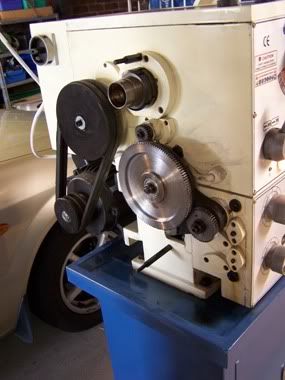
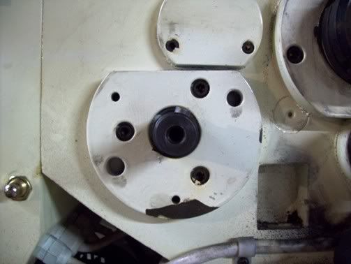
im about to start rebuilding my 12x36" lathe cabinet stand and i want to fit a foot brake and coolant pump has anyone had any luck doing this? i was thinking of using a disc brake from a push bike the cable type and a simple pivoting foot leaver

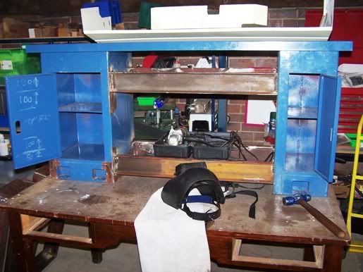
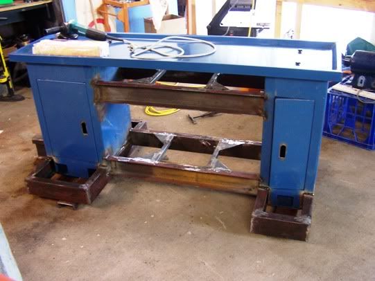
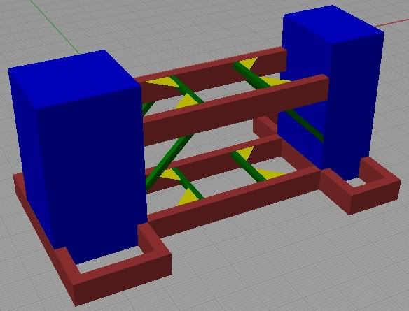
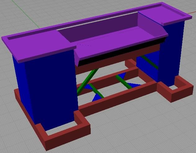
i have my stock all cut up it just needs some cleaning up with a grinder then the lathe is coming down and ill start work hopefully by the end it should look like this

nearlyfinaldesign-chippan.jpg

nearlyfinaldesign.jpg


Interesting idea on the brake . I know some of the commercial lathes have a safety stop bar.
As far as a coolant pump that should be easy . I sort of set one up for my saw but do not realy use the saw enough to justify maintaining a coolant tank.
You should be able to get something like this for under $150
2386-0005.jpg

enco IIRC has a similar one sometimes on sale for a $ 100 I tried to get a direct enco link but it appears the site is down for maintenance.
Or just buy a pump and build a larger tank if you need it.
Tin
 
What type of motor does your lathe have? If it's a normal AC induction motor you can use DC injection braking with good results. It will only work if the motor is directly connected to the lathe without any kind of cluth.
 
I made a coolant pump!!...

Well I cheated somewhat.. I had an old parts washer that had a submersible pump. I removed the impellor from it and made a new pump housing for it..

Shouldn't be too difficult to make an impellor, take a disc of alloy machine a few blades on it. Make the pump housing out of more alloy, minimum clearance between the pump rotor tips, add a suction port in the centre and a discharge port at the edge...Worked well, just make sure the pump is primed...

I'll try and dig up some photos..
 
It just so happens that I have a couple of shots of the brake on my lathe.

Not very good, but they show how mine is done.

Mine works with a couple of brake shoes acting in a drum, the hollowed out section at the back of the drive pulley.

The shoes are fixed to the head and operated by the bar coming up from the footbrake.

The operating bar also cuts off the electrical supply to the motor BEFORE the brake is applied.


workshop101.jpg


workshop102.jpg


At the bottom, I have cropped out some bits from the manual to show you the way it is operated.


Bogs

Footbrake.jpg


drum and shoe.jpg
 
my lathe is pretty similar to yours Bogs i just ran down and checked it out mine only has single speed double belt pulleys and that top stud used to hold the gear cover on is lower on the spindle bearing cap ill see if i have a photo but i think i could use ether that cover stud or those large 3 bolts on the motor bracket to mount the clamping part of the push bike disc brake and as for the disc itself i checked at the bike store i can get some pretty big discs up to 200mm and the large pulley is 150mm diameter so it shouldn't be very hard to mount it on the inner side of the large pulley and that way the cover will still fit ;D on the down side crap from the gears will probably cover it :-X

is it better to mount the brake on the motor pulley or the larger one?

this is the best picture i have of the gear train

100_0836.jpg
 
NG,

If I was doing it, I would go for mounting onto the gearbox pulley rather than the motor pulley.

Mine is in fact an emergency brake, and can stop the machine within milliseconds from full speed, but when I am screwcutting at slower speeds (the only time I really use the brake except in an emergency) I can 'tickle' the brake pedal with my foot, and bring everything to a halt fairly quickly without overloading things.

I expect you will be trying to use a cable operating mechanism because it is much easier to set up than a rigid linkage like on my machine. I personally don't think that will be a fast enough response because of the play to be taken up in the cable first, but I may be wrong. The only way to find out is to try it.

Don't forget the electrical cutout. I actually adjusted mine from the factory setting, making it cut out even earlier, just to make sure the motor really had stopped having power fed to it before the brake came into operation. Just a little thing that I felt was necessary.

Have you thought of putting the brake handle on top of the head?

I am sure you could rig a handle at the top of the head and across the front of it, that you could push down on, that would be a lot simpler than getting a rigid linkage from the bottom of the cabinet to the top.

Just a few suggestions.


Bogs
 
those are some good ideas im looking at disc brakes now on the web so ill have a better idea of sizes i think the cable shouldn't have to much slack when these brakes are fitted they can be very easily adjusted and the cable only needs to be pulled a few millimeters to engage the brake but i think a little slack wont be to bad i am thinking of using a limit switch to turn off the motor before the brake engages so that slack could be a big blessing oh and to adjust the limit switch would be as simple as a grub screw and lock nut

Edit: just an update of where i am at i have looked more into brake options and i think a drum brake will be the simplest, strongest and most effective option i know others have done the same conversion i just didn't know it could be as simple as what it is i now need to get the gearbox pulley off latter i can feel it is already bored out so i dont think it will be much work

is anyone else interested in these improvements?
 
Bogs, mine came "pre-adjusted" from the factory! When threading I can touch the brake pedal which kills the motor then it coasts for a turn or two until I press harder to stop right on target.

New_Guy, I have seen an effective brake made by tensioning a piece of 'vee belt' over a pulley.
 
I would also look at the new mountain bike disk brakes. There are hydraulic and cable operated. Shouldn't be difficult to adapt. ;)
 
i got the gear box pulley off the other night its already bored out and im not sure of the name off it but the cover around the bearing and shaft (i think the bearing may sit in it) has the all the holes and points for a drum brake already machined in it so im going to try and find out if i can find compatible brakes Thm:

as far as i can tell my manual drawing is nearly identical to Bogs but oddly my machine is not lol

i still haven't taken the lathe down yet my ideas on how i was going to go about welding it went out the window when i found out nothing is square right now oh and im going to try and get a proper welding table from work its so huge ;D

edit here is the cover
inputshaft.jpg
 
its a good day today i finished the welding on the stand ill clean it up with the grinder latter and prep it for painting. at this stage the foot brake is on hold but i have put fixtures in place so i can add it latter here is how it looks now

102_1177.jpg


i go back to work next week so ill knock up a chip pan and sort about making a coolant tank so much done but still more to do
 
Back
Top