For Elmers Engine Builders

Home Model Engine Machinist Forum

Help Support Home Model Engine Machinist Forum:

This site may earn a commission from merchant affiliate links, including eBay, Amazon, and others.
B

Bogstandard

Guest
I am just getting to the cylinders and caps on my build of the Mine engine.
I noticed that six seperate sets of 6 radially spaced holes have to be drilled, and they are all the same dimensions.
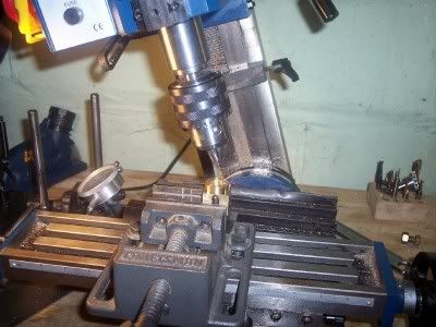
So I decided to make a little drilling jig that required only one set of precision drilling, and either fitted over the part or the part fitted into it so that these holes can be quickly spotted thru and brought to the right size for drilling or tapping later. To use all that is required when the part is being made is to draw a center line that the jig is eyeballed over to get the holes into the right position.
I have also looked thru a few of Elmers other plans and he seems to use standard dimensions, so this jig should be able to be used with a few more of his designs.
The hole thru the centre is 1/2" +0.002" and the larger hole is 15/16" + 0.002".

DrillingJig.jpg


JigInUse.jpg


John
 
I like that idea John!

As you look through Elmer's plans, you will see that 6 bolt pattern on a
3/4" bolt circle on many of his designs. Bore sizes may differ but the
15/16" flange OD is fairly common as well.
Your drilling jig would be very helpful to me. I have a habit of transposing
the X & Y coordinates on a regular basis... :oops:

Rick
 
Bogs:
Great Idea I was planning on making one of those myself. I guess you get the cigar for doing it first.
Tin
 
I'm starting to suspect Elmer had a good stock of 1"x1" brass rod...

Anyway.. on a similar note, anybody have a good way to easily setup and drill the long angled holes from the valve surface to the ends of the cylinder?
 
Don't know how "good" it is but here's how I do it...

Put cylinder in mill vise at the correct angle using angle blocks or a sine bar*.

Indicate the edge of the cylinder end under the spindle axis.

With a tiny, center-cutting endmill, cut a small flat where the hole is to be drilled.

Follow this with a tiny (#00) center drill, then drill the required size steam passage. Use the mill fine downfeed and go especially slowly at breakthrough.

-----------

* I have a 2.5" sine bar reserved for jobs like this. (The good sine bar doesn't go in the milling vise.) Instead of using Jo blocks in the mill vise (gasp!) I turn a short rod to the required length and use that. More than accurate enough in this application.
 
Those angled holes are easy on my little mini-mill.
After drilling the bolt circle for the head,
I just set the column of the mill to the reference angle and use same
method Marv already mentioned. Spot it with a small 2 flute end mill then
drill it through with a 1/16" drill bit.
MillEngineCylinderAngleHole.jpg

I always use a new bit for those holes.
I also do all of the drilling work on the cylinders before doing any profiling
work to the cylinders. That way it still has flat surfaces to grip in the vise.

Rick
 
Shred:
I picked up a 3" ft piece of aluminum 1 inch bar last weekend also have a few 8"+ long pieces of brass.

Here are some Ideas:
1) use a protractor and fine felt pen mark the angle on your vise jaw.
2) use an angle vise set to the proper angle.
3) make your own angle block.
4) Use a method mentions above
Tin
 
I ended up making an angle jig this morning from some 3/4" Al plate I had-- basically a 90' corner, set at an 16.5' angle from the base. It works nicely-- drop the cylinder block in, start the holes with a 1/16" end mill and finish with a drill. If I carefully measure from the edge of the block, hitting the edge of the cylinder bore is pretty straightforward as well.

- Roy
 
That's funny.. I drilled out the corner of my jig before I milled it to avoid dealing with cleaning up the inside corner, but somehow put the hole in slightly the wrong spot. It still works, just looks goofy. I like the pac-man tool.
 

Latest posts

Back
Top