First Engine from Plans - Elmer's Beam

Home Model Engine Machinist Forum

Help Support Home Model Engine Machinist Forum:

This site may earn a commission from merchant affiliate links, including eBay, Amazon, and others.

agr

Well-Known Member
Joined
Jan 29, 2008
Messages
47
Reaction score
0
Well it has finally happened - I have started my first attempt at a model after only 30yrs of being involved with steam (I started driving a traction engine with my grandfather at the age of 5).

Actually I have several models in my collection - all of which were purchased as either not complete or run down & I have completed/restored them over the years. The only other engine I can claim to be my own is one built for odd and ends many years ago (with the assistance of my Grandfather).

However, since buying my new Hare-Forbes AL60/HM10 lathe/mill combo prior to xmas (Grizzly 0516/Seig C6 equivalent) I have been keen to start something from scratch & try to work to drawings rather than the trial and error approach.

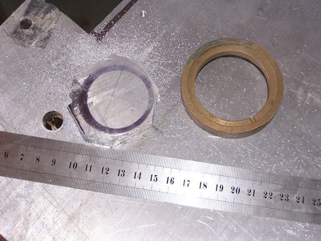
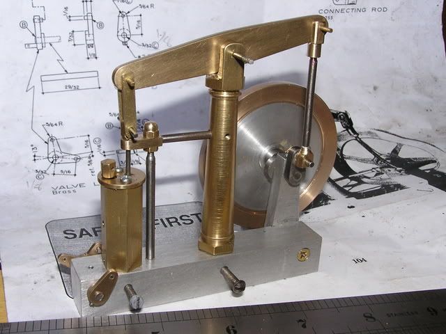
Originally I was going to attempt Elmers wooden Grashopper engine as I though wood could be easier/cheaper to work with but I am still unable to find a source of the 7/8" brass tubing required for the cylinder. However, scrounging around my boxes of odd & ends I found enough material for the beam engine.

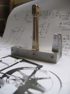
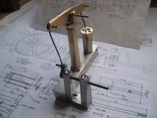
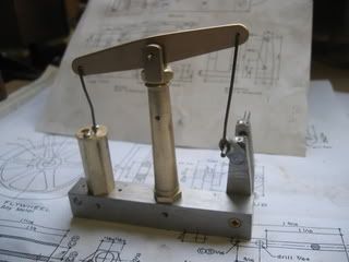
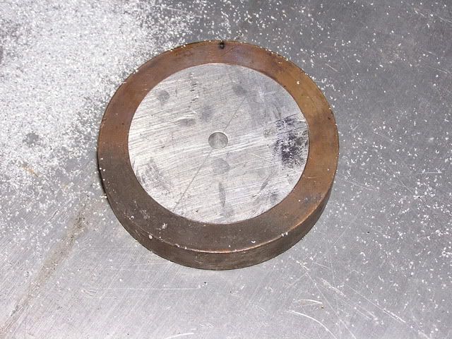
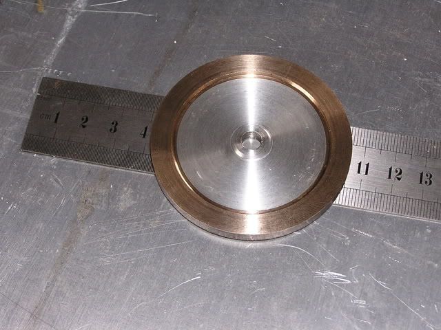
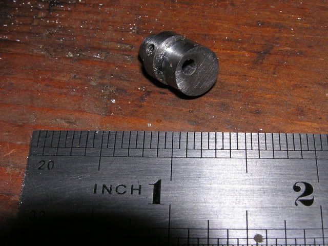
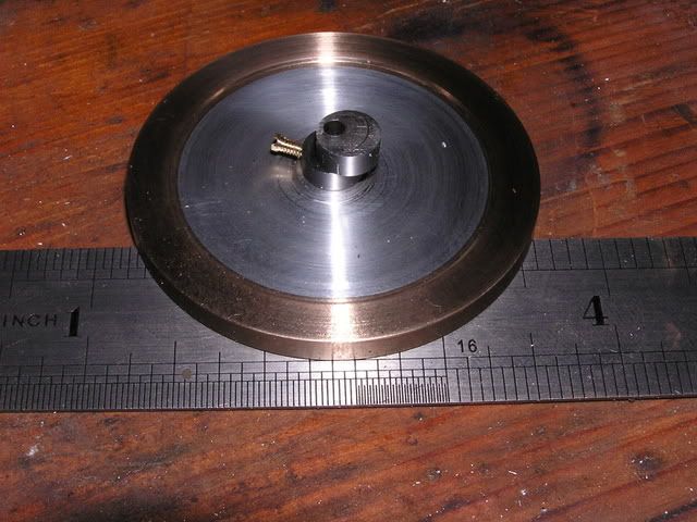
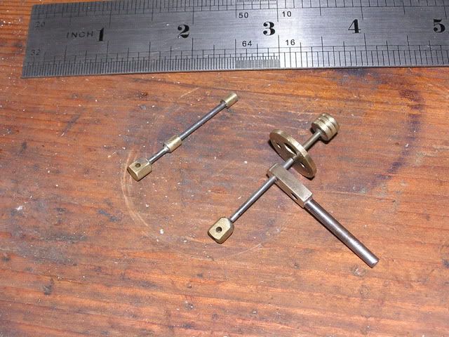
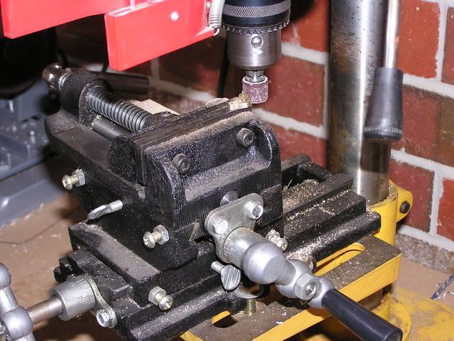
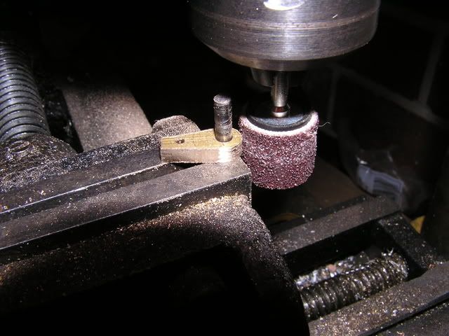
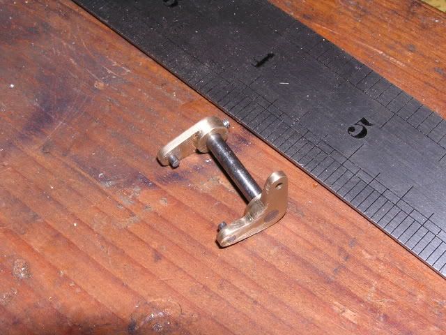
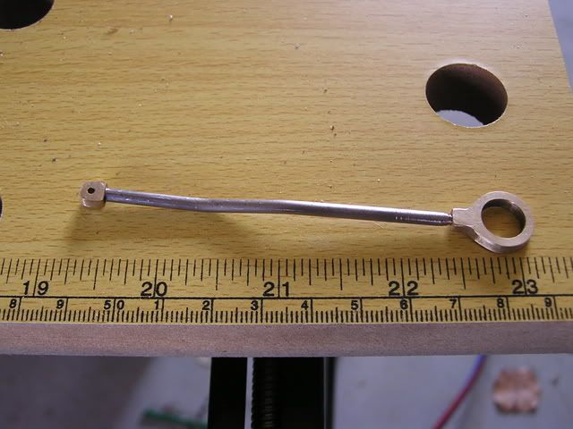
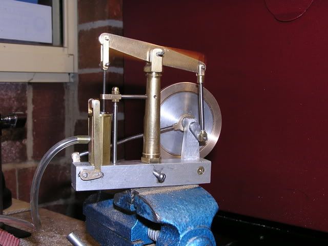
Below are photos from the first days work. Yes it's not a lot of progress for a day but milling the 1-1/4" x 3/4" alluminium bar to 5/8" x 5/8" given my complete lack of experience on a mill did prove to be a learning exercise on possible feed rates, cut depths, etc (plus why you need a proper mill vice and not a modified drill vice).

IMG_1900.jpg


IMG_1898.jpg


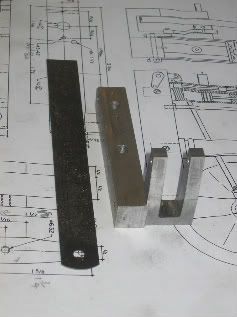
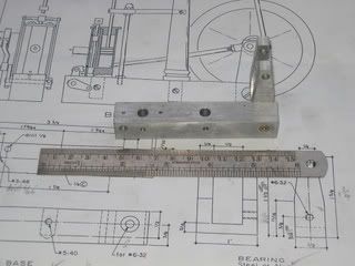
I have made some minor changes already - I have replace threads where possible with 1/8" Whitworth as I can get plenty of 1/8 stainless bolts from the local hardware stores (even though Australia has been metric for how long???) but UNF threads aren't so easy.

It may be some time before I get back into the shop & at this rate of progress the complete engine may take quite a while to finish, but at least it has moved from my "Projects to do list" to the marginally shorter "projects to finish" list.

Tony
 
You've picked a good design to start on Tony.

My own build of that engine was a little rough.
OK most of my builds are a little rough, but that one was rougher! :D

None the less it runs.

Please keep us posted on your progress!

Rick
 
Good luck Tony, I know what you mean, in my case I am "under pressure" to complete a lot of unfinished work around the house ??? .... ces't la vie' etc ??? ........... hopefully come Christmas time we'll both have a little more engineering achieved ;) ....... and hopefully my "to do" list (Wife's version that is) will be a little shorter ::) ...... as if :wall:

CC
 
Well despite the fact that I am suppose to be home on leave to keep the kids entertained through the holidays, I did manage to sneek back out to the garage this morning and complete the column.

This was a little more relaxing than producing the base/bearing as it wasn't so dimensionally critical (except location of holes, etc). However I was quickly reminded when milling the slot at the top that

feeding in the wrong direction (climb milling) + saddle backlash = crunch!!!

luckily no damage was done as I wasn't close to the final dimensions.

Rick - it was photos of the beam engine on your website that provided the motivation to choose this project. Its one thing to review plans, but another to actually see photos of how it is built and assembled.

Anyway, here is a photo of the completed column - I wasn't aware of how bad the tooling marks were until I took the photo but if that is the worst looking part of the completed engine I'll be happy.

IMG_1904.jpg
 
Hi Tony

Its looking good, though I know what you mean. Cameras are far too clever for their own good these days. They seem to delight in seeking out and exagerating every single blemish.

I also know what you mean by getting caught out by climb milling. I have put a big diagram on the wall next to my mill to remind myself of the difference between right and wrong - I seem to have a mental block on the subject.

Anyway I look forward to seeing your build develop.

John S
 
That's looking great Tony!! I think Elmer's beam was my second or third build but still one of my favorites to see running. Please keep the progress pictures coming.

Bill
 
Found some more time for the shop today and completed the crank, cylinder and cylinder head. A couple of minor errors in the cylinder head (eg. drilled the valve rod hole off centre) but it will do for now - I may remake it next time the four jaw is fitted in the lathe. I have also modified the design slightly by adding some brass bushes for the crankshaft, rather than running steel in aluminium (also easier to replace).

Below are a couple of photos. The brass wire "connecting rods" are only temporary - firstly to check that everything seems ok so far (found that I had to relieve the sides of the column slightly to allow the beam to pivot full stroke), and secondly because I wanted to see something moving!!


IMG_1906.jpg


IMG_1905.jpg

 
Hi AGR
that's looking great, I have the same plans in front of me ready to go. i love the look of this engine and your pic's and writing is enough to spur me on to get started. Thanks for that. Please keep posting it's great to watch it coming together.

Kind regards

Malcolm
 
Well, the boss says I have too much annual leave accrued so this week I took the week off to catch up on some projects.

Between the domestic duties and the list of odd jobs waiting, I have managed to get some time in the garage to progress the beam.

I felt it was time to tackle the flywheel. Unfortunately I only had one piece of brass large enough to carve it from and it seemed a waste to machine most of it away (knowing that down the track I'll be looking for a disk of 3 1/2").

However, I did have a brass ring a bit over 2 1/2" OD, roughly 2" ID and a large aluminium plate (about 16mm thick).

So I decided that I could carve a round disc out of a piece of plate and press/shrink it into the brass ring.

The photo shows the brass and the roughed out aluminium (Note to self: must move a bandsaw further up the "to buy" list).
P8262896.jpg


I lightly bored the inside of the ring to give it a smooth finish but not having a live centre to try out bogstandard's method of turning from plate http://www.homemodelenginemachinist.com/index.php?topic=228.msg1394#msg1394 so a 3mm hole was drilled near centre and a bolt passed through. The shank of the bolt was gripped in the 3 jaw, the head of the bolt centre drilled and held with the dead centre while the outside was turned round to just over the ID of the ring.


I then used the butane camp stove to heat the ring then "tapped" the aluminium plug into it with a large persuader.

P8262897.jpg


The flywheel was then turned to shape, leaving the OD a little rough until it could be mounted on the shaft.

P8262898.jpg


I was considering attempting to cut the spokes out as per the drawings but figure its looking good so far and don't was to risk distroying it and assume the aluminium centre/brass outer will give the desired intertia effect. Maybe when I get a rotary table I can rework it?.

Anyway, got the hub/eccentric machined and pressed into the flywheel, well actually made three - the last one actually came out to the correct size and correct throw.

P8262900.jpg


P8262901.jpg

 
Tony,

Forget what the finish is like, get the engine running.

If you can achieve that, it will give you a big boost, and then you can try cleaning it up a little. One step at a time.

It is coming on really well.

John
 
Hi Tony

Its looking really good and I like your ability to adapt to available materials and to work within your present machining facilities. That flywheel is great !

Bogs is quite right on the subject of finish. I used to get very frustrated when I couldn't get the standard of finish that I thought people expected. Fortunately, as Bogs advised me, finish is one of those things that seems to improve steadily as your machining skills develop.

I am sure I am not alone when I say I am looking forward to further progress reports.

John S
 
Down to the smaller parts now. The piston and valve are done, actually this is the second piston (3rd piston rod). Initially I misread the drawing (or the imperial/metric conversion) and cut the rod too short. A longer rod was cut and re soldered to the piston, only to find that the cylinder bore had a slight taper to it. Long story short - I got the piston jammed 3/4 of the way down the cylinder & quickly found how easy it was to bend 1/16" silver steel (drill rod). After finally freeing it I had to polish up the bore & machined a new piston to size.

P8282909.jpg


This photo is actually the second I took. After taking the initial photo I had "one of those moments" - possibly one familiar to others who have build this engine - I had silver soldered the piston and 'little end' to the rod - but forgot to build and put the rod guide on first.


Moving on, the valve rocker arms were cut from brass plate and shaped. To try and get a better shape to the radiused ends I decided to try using the compound vice in my drill press with a small sanding drum from my "dremel" style drill kit. Mounting a piece of rod in the vice, I progressively fed the material into the drum while pivoting it back and forth. I have seen others demonstrate a similar process in the mill, but I was much more confident with my finders that close to the low power drill chuck & sanding drum than a 'bitey' end mill.

P8282907.jpg


P8282903.jpg


P8282908.jpg


With the connecting rod also now done its getting close - just a few linkages, the eccentric strap & rod, & its ready to test run.

P8282910.jpg
 
Hi Tony from another Tony also with a Hare & Forbes AL-50Gb lathe but without the mill attachment.

That's coming on lovely. I'm still just making simple oscillators at the moment but each completed part gives me more confidence.
Look forward to seeing it running.
 
Beautiful work Tony!

I only know of one other person who could have been dumb enough
to solder that valve rod together before placing in the head.

That person would be ME!
Been there, done that... :-\

Looking forward to more pics.

Rick

 
Beware/Aware Malcolm, these cross vice assemblies are not super dooper pieces of engineering, and you will probably have to do a mod or two to get it usable. I think one of the forum members gave a description of what he did to make it a bit more accurate, slide fits seems to ring a bell.
Regards Ian
 
Hi Ian
Thanks for the advice, I realise its not made to engineering excellence standards (the Price gives this away) however i can see if it where fettled a little it would save some time in certain jobs. (now where is that fettling thread ?)
that's what i like about this place, helpful, friendly, experience driven ideas offered and no put downs for the newbie. Where else could you find that ?

Many thanks

Malcolm
 
Firstly thanks for all the comments/support. Like many others have commented on this forum elsewhere, it is nice to have somewhere like this to share & learn without being expected to have a trade background and years of experience, or the most elaborate workshop setup.

Malcom, the compound vice was purchased a couple of years ago and has been very useful. Admittedly it is not ultra precise, but it does make work holding/positioning in the drill press easy at times. And yes, I did try and use it as an improvised milling machine and while VERY light cuts in brass/aluminium were possible, the finish was not good and the bearings in the drill spindle may never be the same!

Secondly IT LIVES!!!!!!

The eccentric rod/links were completed today and fitted. The pivot pins are still just pieces of scrap, and there is still much cleaning up to do, but I just had to try it on compressed air.

P8292911.jpg


P8292912.jpg


Initially it wouldn't go, but a small adjustment of the eccentric rod length to correct the valve travel, but it was still a bit tight. I turned it over for 30 sec or so with the power drill, reconnected the air and off she went.

I managed to get a short video - unfortunately my "vintage" digital camera does not record sound. Actually it may be fortunate, otherwise you would all hear the air leaking out past the valve - but who cares right now IT RUNS. As my late grandfather you to say, the beauty of a steam engine is that it can leak out of every joint and orifice - but still run, where as an IC engine is much less forgiving.


I've had it running for 20minutes or so now, and can get it to run at a more relaxed pace, at about 20psi, but as I said, I thnk most of the air volume is blowing by the valve.

So it looks like a little rework on the valve during the cleanup, but its "finished" and running just in time to return to work after the end of my week's leave.

 
AGR---Amazing job. It appears to be very well crafted and a definite runner. Geez, for some reason it looks awfully familiar----Brian
 
Nice job, I need to get my mill up and running so I can learn new ways of making scrap metal.
Keep up the good work.
 

Latest posts

Back
Top