Engraving Without CNC

Home Model Engine Machinist Forum

Help Support Home Model Engine Machinist Forum:

This site may earn a commission from merchant affiliate links, including eBay, Amazon, and others.

kcmillin

Project of the Month Winner!!!
Project of the Month Winner
Joined
Jan 19, 2010
Messages
1,193
Reaction score
41
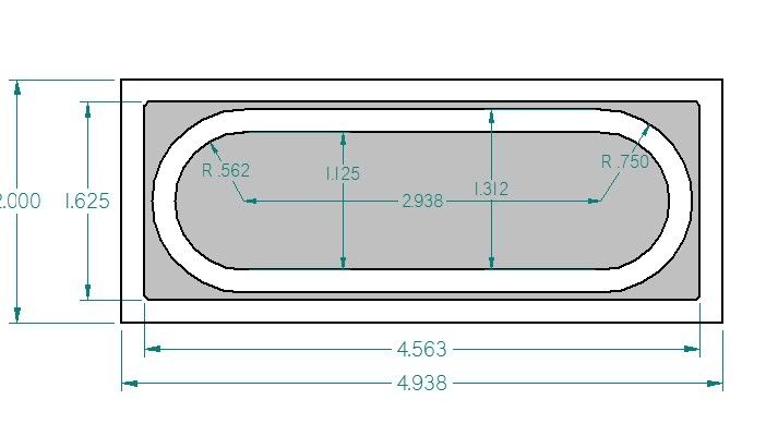
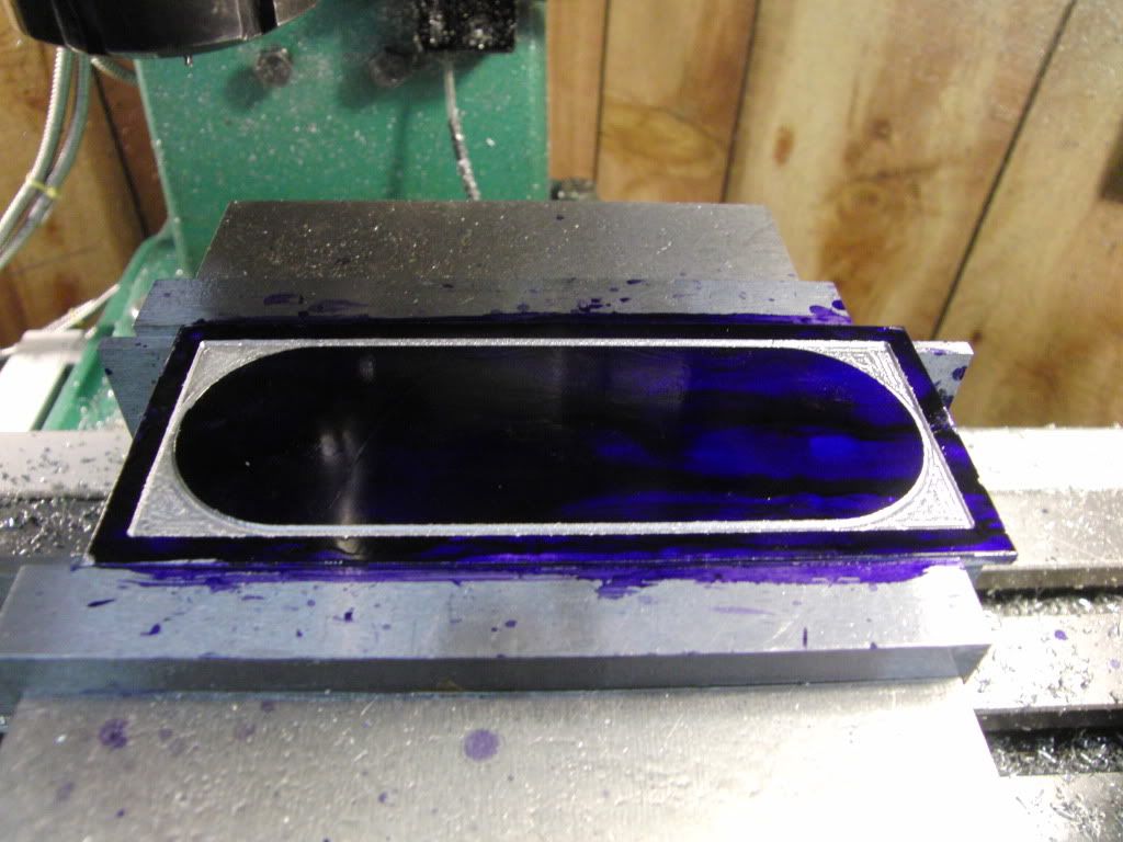
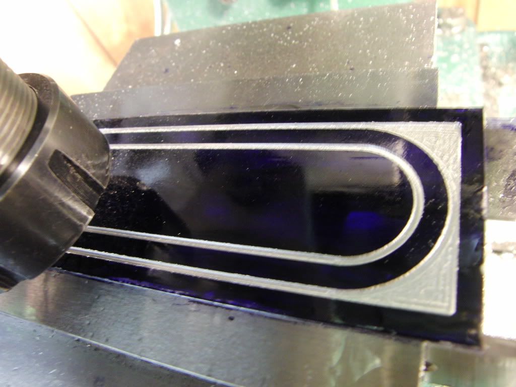
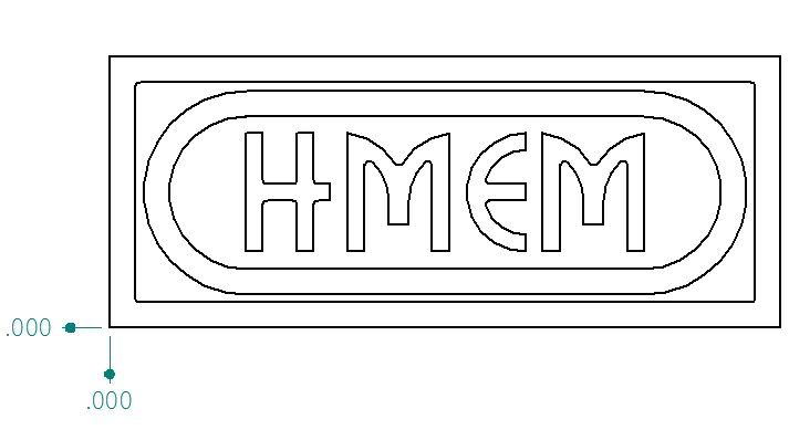
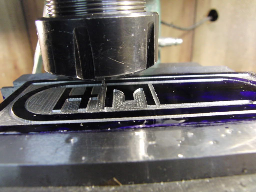
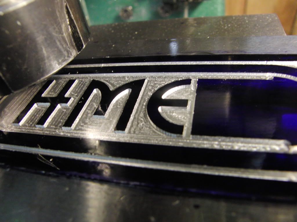
I recently Discovered I could make engrave letters or other complex round or angled shapes using my Computerized DRO. So I thought I would share exactly how I did it.

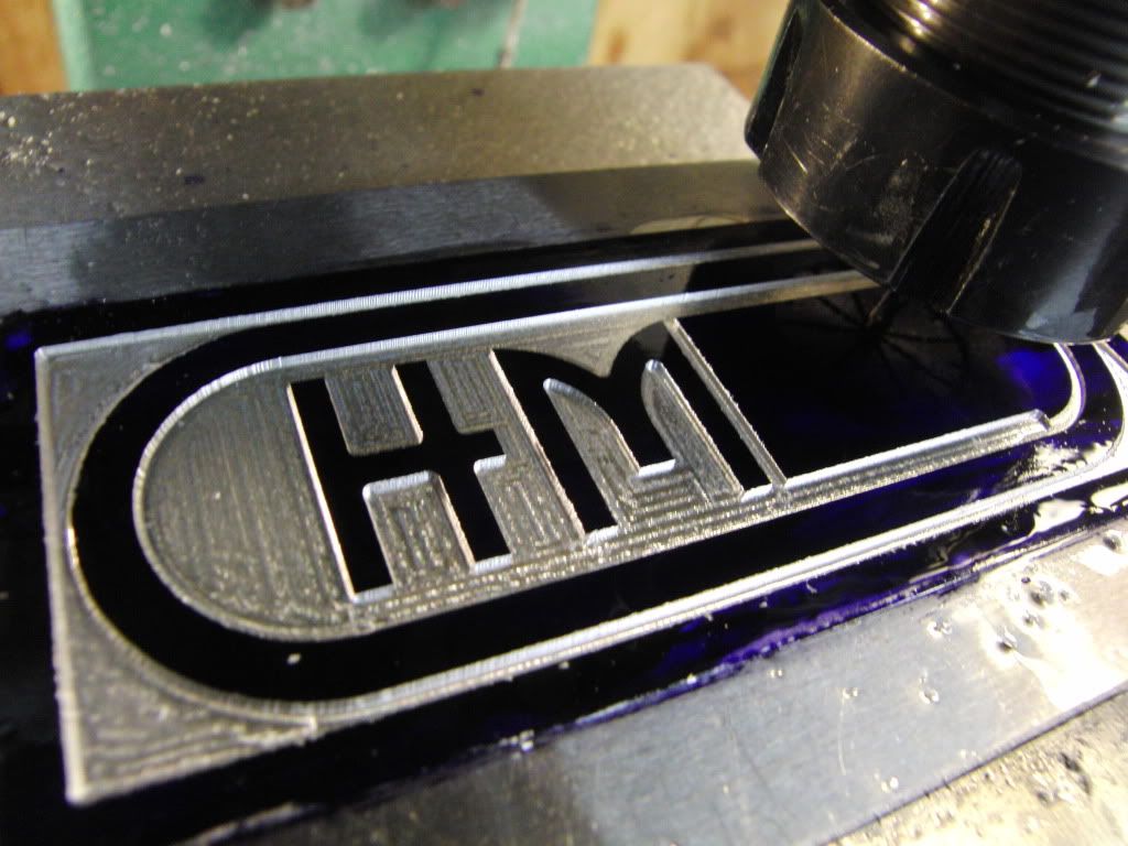
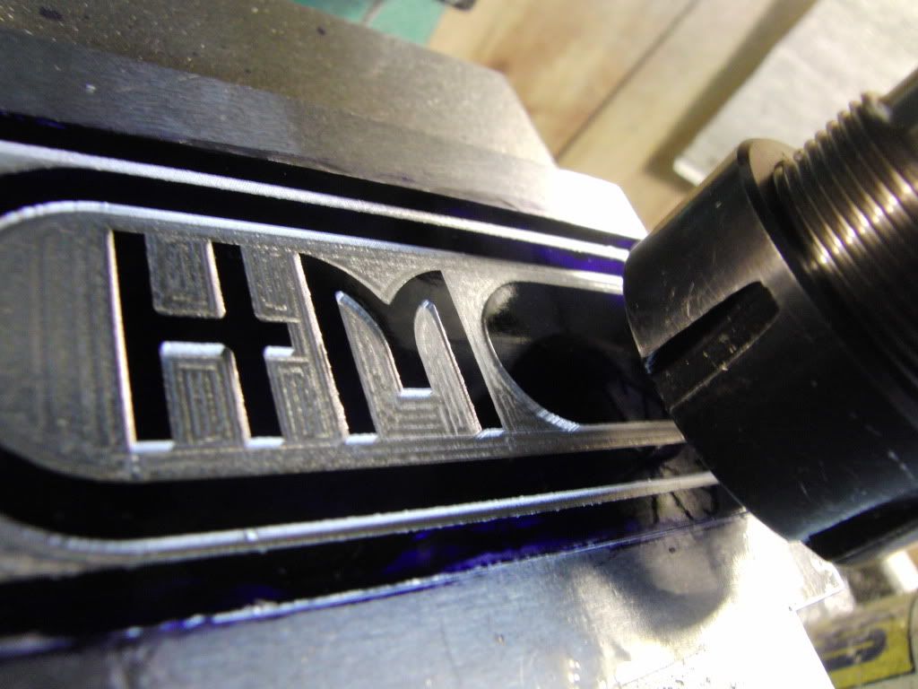
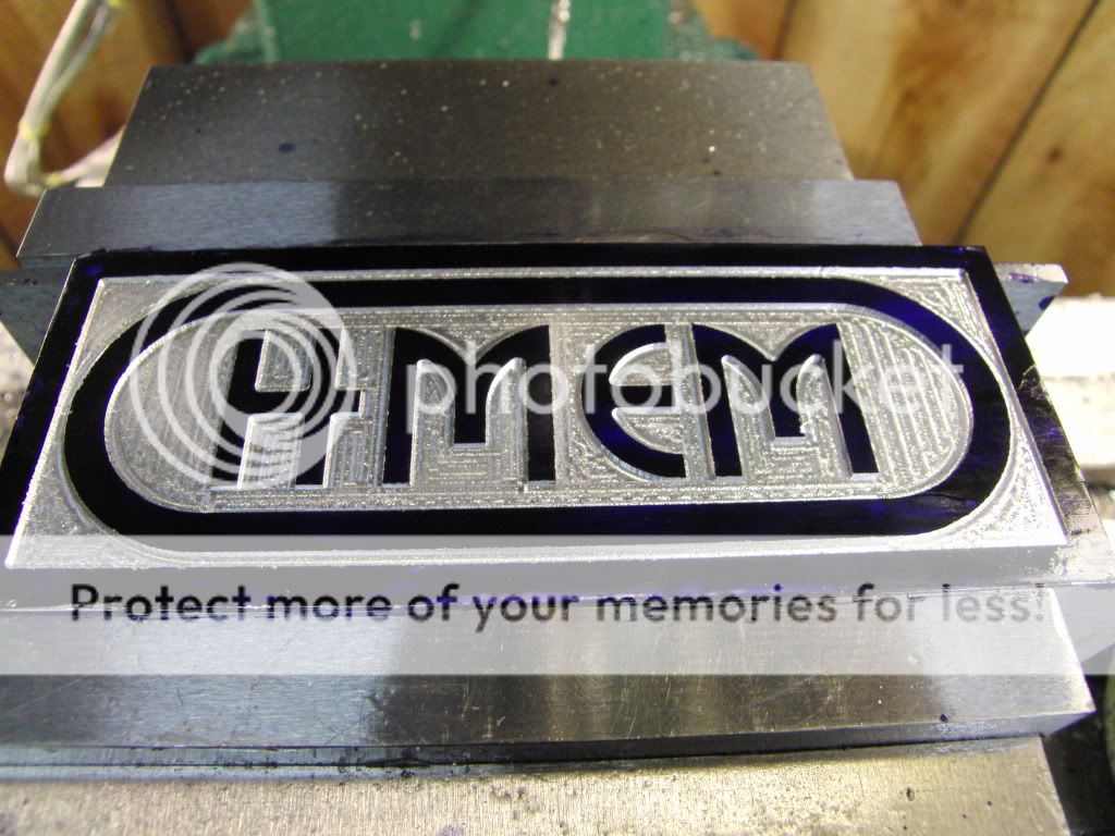
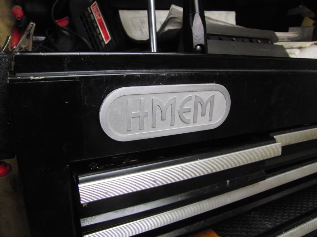
Here are a couple examples of what I have done so far.

CIMG1962.jpg

CIMG2063-Copy.jpg


I am going to do this in a few installments, and try to cover as much as I can.


Firstly I am using a DRO with computer functions like inclined, and radius milling. This could be accomplished without a DRO using mathematical formulas and a notebook full of Co-Ordinance's, or even a rotary table and an angled vice, but for now a DRO is the easiest way.


To Begin I will show you how I draw the letters. It is important to know the layout of the letters before you start thinking about milling them.


Drawing the letters is a pretty straight forward process.

Virtually all letters and numbers, aside from M and W, can be drawn in a 3 accross by 5 high grid.

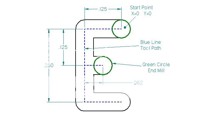
There are a lot of easy letters to make like E, H, T, and all the straight ones. Here is an example of an E drawn in a 3 X 5 grid. This grid I am using is made up of 1/8" X 1/8" squares. This will make 1/8" lines. You can do this on graph paper, but using a 2D drafting program makes it a lot easier to draw up, and figure out the positions of cutter in relation to the letter. I am using Solid Edge 2D, it is a free download and a complete version, no restrictions, verry easy to use, and makes finding hidden dimensions a breeze.

1-2.jpg


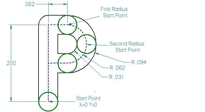
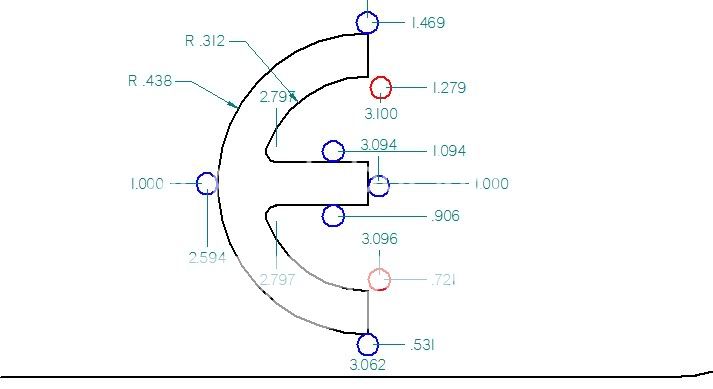
The more complex letters are also drawn out in the same fashion. The radii of the circular sides are the same as 1/2 of the width of the Grid, in this case its 3/16"

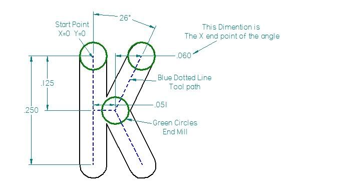
The S consists of two 3/4 circles connected in the middle. An the R includes a 20 degree angle which connects at the circle. When you draw up your letters you will have to account for the width of the cutter you will be using, and you will have to play with angles to get the shape you are looking for. I will go into more depth on this later, this is just to get you familiar with the drawing process of letters.

3-2.jpg


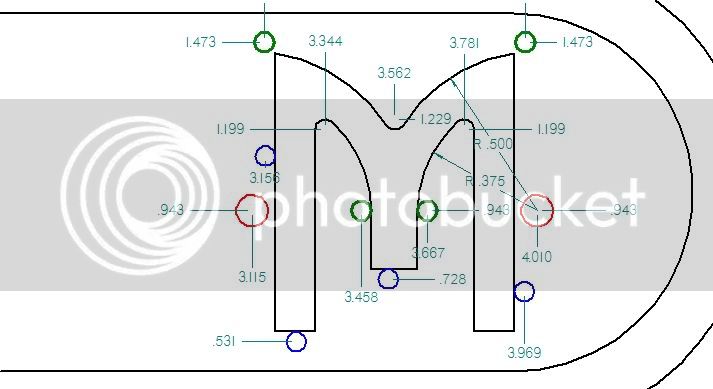
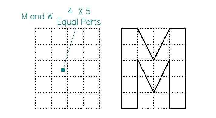
I mentioned earlier that the M and W would require a different grid, Here is a drawing of a W on a 4 X 5 grid. These letters are more stretched out than the rest.

2-2.jpg


So, thats it for the simple drawing of the letters. Next I will go into depth on accounting for cutter diameter when milling the letters.

Kel


When You are designing you letters you must always remember that the diameter of the tool will dictate what they look like.

There are two types of engraved letters, raised and recessed. I will start with describing the simplest method, which is recessed.

You can make recessed letters in two ways, either using the same size end mill as the line width of the letter, or using a smaller end mill and milling out the letter in more steps. I will describe using an end mill the same size as the line width.

When making letters you must come up with a plan. Figure out the path the tool makes, where to start and where to finish. Each letter will have a X-Y co-ordinate in relation to the workpiece for the start point, I like to Zero the DRO in the incremental mode for each letter.

We can start with something simple, like an E. The end mill I am using is 1/16" four flute. So the total dimensions of the letter will be 3/16" x 5/16"

This is all straight lines and pretty straight forward.

I like to write up every step for each letter ahead of time so I have a cheat sheet when I am milling.

It goes like this.

1. Zero point -plunge Z to depth (I use .016" with a 1/16" end mill"
2. Move left .125"
3. Move down .125"
4. Move right .0625"
5. Move left .0625"
6. Move down .125"
7. Move right .125"
8. Lift cutter---Done.

Here is the Graphic.
5-2.jpg


Next up is a more complex letter.

Kel

 
OK, this is when having a DRO with calculator functions come into play.

My DRO has two radii functions, The Simple Radius and the Smooth Arc. I will be explaining the Simple Radius. Most computer DRO's have this function.

I will be making the letter P now. It consists of four straight lines and two arcs.

The inner radius is what I will be typing in the parameters. When you setup your DRO you must set it so it knows where the tool is. On my DRO I must choose "Radius + Tool" when making an outside arc.

The radius of the arc here is .03125"

My DRO requires you to input what type of arc you are machining. IE, up and to the left, down and to the right, left and down, and so on. There are 8 different types of Arcs on my DRO, and I had to re-number them all, as they were different than the manual stated. You might want to check this on yours to be sure.

I am using a max depth cut of .012" on the radius. This makes 10 Way Points for each arc.

Here are the steps for making a P.

1. Zero Point Plunge Cutter to Depth.
2. Move up .250"
3. Move Right .0625"
4. Zero both axis. Setup Parameters. .03125" radius Arc, Down and to the Right
5. Zero Both Axis. Setup Parameters. .o3125" Radius Arc, Down and to the Left
6. Zero X Axis. Move Left .0625"
7. Lift Cutter-------Done


6-2.jpg


Next up I'll show a letter with angles.

Kel
 
I will be using the inclined milling function to make the angled parts of letters like V, Z, and K. This function is typically used in combination with a DTI for checking the angle of a workpiece.

On my DRO when this function is enabled the X axis display shows the actual movement and the Y Axis displays the error between them for whatever angle. For instance, if I have it setup for a 45 degree angle and I move the X axis 1", than the y axis error reading will indicate 1", then you move the y axis until it zeros out and you have two positions 45 degrees to the axis of the table.

So, when using this function to mill an angle I need to know at how far the X axis moves for the total length of the line. Since the Y axis only shows the error we must know the X, since its actual movement is inducated. I call this the angle end point. (Shown on Drawing)

You must also know the angle Start Point, since this will most likely be different than the letters start point.

Once you know all the points it is time to mill the line.

When I am milling the angle I move no more than .005" at a time. Meaning if I move the X Axis .002" but the Y axis shows an error of .005, than it is time to zero the y axis before moving the z axis again. Do this repeatedly until you reach your angle end point.

Here are the steps for making a K

1. Zero Axis Plunge cutter to Depth.
2. Move down .250"
3. Move up .125"
4 Move right .051". Zero both Axis. (This is the start point for both a angles)
5. Setup Parameters for a +64 Degree angle. Mill To end point.
6. Lift Cutter and reset on the point defined in Step 4.
7. Setup Parameters for a -64 degree angle, Mill to end point.
8. Lift Cutter-Done

4-2.jpg


That should cover what I have done for simple Recessed Letters.

Next up will be Raised letters.

Kel


Nice work Kel, and well illustrated too. I was able to follow along pretty well until you got to the angled parts. Somehow I got confused, but I guess you are saying that you use step cuts in x-y increments to cut the angles?

I don't have a DRO so maybe it's just escaping me through a lack of DRO experience. Must be a Sine/Cosine thing?

I've used a totally different method before (just to see if I could do it) using a scriber affixed to the head of the mill with a paper printout on a tray attached to the mill table. Followed the lines on the drawing via the scriber/pointer and eye-hand coordination of the x-y control handles.

It works well too, but not as nice as your method. Simpler, but subject to coordination errors. The eyeball method requires that you draw the parts with the tool offset lines shown so you have the right lines/arcs to follow.

This post is very interesting to me since I also have a home made pantograph that I use from time to time.

Rich
 
Hi Kel,
I did a similar thing when I built my Holt radiator. I have a Chinese scale DRO so I don't have all the functions that you do. I drew up what I wanted, laid out the mathematical points and cut with a .062 end mill.
George

Holt radiator4.jpg
 
Rich, that is a good Idea with the scriber! You are correct, the angles are made in steps, and the DRO displays the error from the Y to the X. There is virtually no math involved, the DRO does all the thinking. When I make the angled I try to keep the movement between points no more than .005". This makes a pretty nice line.

George, that looks great. And thanks for showing it, and proving you don't need a fancy DRO to make simple letters. Did you have the part at an angle when milling out the tops of the letters?

Kel


PS. Here is a preview of the raised letters I will explain, these are a little more complex, but most procedures are the same. Some liberties were taken in the drawing process to get the right look, and I will be using the "Smooth Arc Function" instead of the "Simple Arc" With Smooth Arc, you control more parameters and can get portions of a circle instead of one complete Arc.

7-2.jpg


I'll be sure to follow along with your next presentation. Should be interesting!
Rich
 
Hi Kel,
Yes I had the rad turned to do the angular top edge. I cut all the stock around the outside of the shape before starting with the small cutter.
George
 
OK, when making raised letters there is a lot more to mill out than the recessed letter method. Essentially you must remove all the material that is not the letter. It is a much more time consuming process than recessed letters, but you can get pretty fancy with it.

I like to mill the outlines of the letter first, and then milling the bits in between spaces out. I also start with the border, so I have somewhere to run the tool into when making the letters.

here is a graphic of the border, I will be showing all dimensions in case someone wants to make this.

This was all done with a 1/16" end mill, and all the co-ordinates are for this.

8-2.jpg


Here is the border getting milled out.

CIMG2066.jpg


CIMG2067.jpg


When I make raised letters I like to go with an absolute co-ordinate measurement system. Each letter will have its co-ordinates in reference to the edge of the workpiece, or sometimes in the center of the workpiece.

here is a graphic of where all the next co-ordinates will be taken from.
13-2.jpg


here is the start of the H. I milled all the material out to the left of the letter.

CIMG2068.jpg


Here is the numbers for the H
9-2.jpg


and the milled out H

CIMG2069.jpg


Here are the co-ordinates for the first M

10-2.jpg


Since these radii are not complete half circles, I will not be able to use the simple Arc Function. My DRO is equipped with a "Smooth Arc" function which allows you to controll all the parameters of the Arc.

Firstly, you must enter the center point of the circle, on the graphic these are in Red. you must also enter the start point and the end points of the Arc. The end points are in green. The start points are the same as the inside corners of the letter. All these co-ordinates are in the Absolute measurement mode.

I set the max cut at .025.

The bottom of the M
CIMG2070.jpg


The finished M
CIMG2071.jpg


Here is the E co-ordinates.

11-1.jpg


And the E getting milled.

CIMG2072.jpg

CIMG2073.jpg


Now the second M

12-2.jpg


And the finished Plaque.

CIMG2074.jpg


Let me know if you have any questions regarding this. I am not a writer, nor an educator, so some of this may be a bit hazy, but I am pretty sure I made it understandable.

Kel

For those wondering this took about 4 and a half hours to machine, so not any type of competition for CNC, but If you only need to do some simple lettering on a limited basis, this is much cheaper.


Nice job Kel!
I totally understand how you did it, but it must take the patience of a saint.
Thanks,
Rich
 
kcmillin said:
I am not a writer, nor an educator...

But you are an educator, Kel. Just got done reading this. Excellent!
Thank you.

Dean
 
Thanks Rich and Dean. I am glad you understand it.

To finish the part I decided to cut off the outside border and make it more pleasing to look at, then I sandblasted it and then sanded smooth the raised portions of the part. This provided the necessary contrast to show the letters off a bit more.

Here it is in it's new home, a new badge for my toolbox. ;D

CIMG2076.jpg


Thanks for looking in.

Kel
 
Kel,
I had no idea that there were DRO's with complex functions. I am asuming that the arc's were made similar to the description of the K and small movements were made in one direction and the error corrected in the other direction.

Who makes the DRO you are using?

Thanks for the explanation.

Dan
 
Dan, I am using a DRO Pro's 3 axis Mill Kit. They seem to have the best service. Although a little more pricy than some on E-bay, a 3 year warranty is nice. I also did some/ a lot, of research and found out that most of the cheaper glass scale dro's are limited to metric in most of the functions, although this may not be a problem for some, I do all my work in inches. These are between $450 and $800

Here is the one I bought. I am very pleased with it.

http://www.dropros.com/DRO_PROS_Milling_Machine_Digital_Readout.htm#DRO_PROS_3M


Most Computer DRO's on the market have simple Arc Function and Inclined Milling Function. Also, a Bolt hole Pattern function can be manipulated to do the same thing as the Arc. Do some research and make sue the one your looking at has these functions.


When machining the Arc, it gives you a set of way points based on the max cut parameter entered. You start on way point 1, which is zero-zero. You must then click a button to show way point number 2. When you change to way point 2 both the X and Y axis shows a reading, what you have to do is then move the table to "Zero" out the display, then click the button to display way point three, again the display changes and you must zero out the screen.

As your milling the Arc, the difference between the two readings changes. In order to get the smoothest arc possible you have to move both axis at the same time, and close to the same rate.

Example, if you click to way point number two, and it displays .020 in the X axis and .002 in the y axis then you must move the table two different distances in the same amount of time. What I like to do is divide each number by two in my head, then when moving the table get both these numbers to meet up. So that means I would move the X axis until it reaches .010, and in that same time move the Y axis to .001, then complete the movement at that rate until both axis display Zero. This can get a bit tricky, and you always must remember which hand is controlling which axis. I like to look at the space between the to displays and read both at the same time in my peripheral vision.

Hope that helps.

Kel
 
Amazing work Kel. :bow:

Really nice walkthrough, I suspect your being a little too modest when you say you are not a teacher. I don't have a DRO on the mill yet, but it is something I have wanted to do, this just makes me want to do it even more.

Thanks so much for such an excellent write up, will bookmark it for later digestion.
 

Latest posts

Back
Top