Elbow Engine?

Home Model Engine Machinist Forum

Help Support Home Model Engine Machinist Forum:

This site may earn a commission from merchant affiliate links, including eBay, Amazon, and others.

kvom

Well-Known Member
HMEM Supporting Member
Joined
Jun 4, 2008
Messages
3,285
Reaction score
630
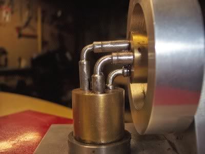
As I get close to completing my first model I am thinking of trying to build an elbow engine as the second.

There are free plans for a 3-elbow model posted on this site, and I also found plans for a 5-elbow engine on the web for $11.

I would appreciate any advice. I understand that getting the elbows precisely at 90 degrees is the finicky part.
 
Hi

I've been doing a bit of research on building an elbow, from what I've been able to glean:- its not an easy engine to get running, making the bits dosn't take long but tunning all the gremlins out to get it running takes an age. :mad:

From what I understand the critical features are squarness, alignment, and friction.

So when you machine it you have to pay particular attension that you get these features absolutly spot on.

The instruction for a 3 elbow from the site, are very basic, if you are to stand a chance of getting a running engine, you'll have to refine the design, for example the centre pin neads to screw down to a shoulder to get it square, and its length has to be spot on the same as the cylinder, to just use the cap screw as shown in the plans will lead to failure.

Also the plans don't tell you lubrucation is very important.

Having said all this don't be put off from having a go at making one, its a facinating engine to see running, and well worth the effort.

Good Luck

and have fun

Stew

 
One of our club members built the five elbow design using the plans from LMS.

He reported that there were errors in the plans so be forewarned if you choose that design.

Now finished, his engine is beautiful and works very well but he had to fiddle with it for a very long time in order to reach that point.

Mine was a scaled down version of the three elbow design from "Popular Mechanics". A simple build but I spent an eternity tweaking the angle on the elbows to get it to run smoothly.

Don't let me scare you off. It's a fascinating engine and a real crowd pleaser but it does require a generous dollop of patience to complete.
 
Well I'm going to jump in here and say that they're lovely engines to look at and to make but they really are a pig to get running, as all above have said, you can have a nice running fit with the pistons and cylinders but if the pistons are not all exactly square, you'll end up pulling your hair out!, when I made mine, all relatively simple machining, I spent hours and hours trying to get it to run to no avail ,to the point where I lost faith in my own abilities and didn't go in the shop for a week or so!,(I nearly took my biggest hammer to it!)

Saying that, I did eventually get it to run for about 5 minutes (the next time I tried to fire it up, it wouldn't!) it's now under the bench somewhere, one day I guess I'll find some more patience for it!

I basically just wanted to say that it's a very frustrating little project, by all means have a go but maybe make it alongside another easier to get to run engine, so that you can ease your frustrations on that!, after all the beautiful work you've done on your first, we don't want you giving up!!

Giles
 
I reread Rick's and Bog's threads. It looks as if the 3-piston version would be hard enough without going for 5. I will probably make a start on this in the background. I still have TB3 parts to make, TB2 parts to assemble, and the beam to finish.

I may also decide to build Kerzel's V2 CO2 engine as the next one. I like the look of that one and it seems within my skill level.
 
Just a thought!! ??? Wouldn't it be easier to link the pistons with a flexible elbow? I was thinking in the line of some kind of spring or a piece flexible shaft type of material. :-\
 
Noitoen said:
Just a thought!! ??? Wouldn't it be easier to link the pistons with a flexible elbow? I was thinking in the line of some kind of spring or a piece flexible shaft type of material. :-\

i was thinking the same thing. like one of those springy things from like snapon tools flexable socket extention
 
The power stroke involves pressurizing the cylinder bores
at both ends of one of the pistons. I'm not sure of how a flexible
elbow would respond to that pressure. Having the pistons, cylinders and
bores perfectly tangent is critical. I'm thinking a spring link would
create a binding effect in the bores.
Other thoughts?

Rick

 
But then you couldn't brag that you'd built a six cylinder engine with only five moving parts. ;D
 
rake60 said:
I'm not sure of how a flexible elbow would respond to that pressure.

A speedometer cable is only flexible to the sides, which would solve the (I think) complicated bending of the elbow, thus the perfect piston non-alignment/squareness problem solved. The constant distance between the piston would stay constant because the cable doesn't stretch. ;)
 
rake60 said:
I'm thinking a spring link would create a binding effect in the bores.
Other thoughts?

Rick

I've been lucky enough to have inspected an engine that runs exceptionally well and was able to twiddle with it and Rick's spot on about the binding effect I doubt a flexible drive would work. Its interesting when you look at the wear on the pistons what you get is a herringbone effect, the fit of the cylinders in this engine are quite lose. Another thing to note is that when running it is quite greedy for lubrication and the type of lubrication is critical, it needs a sticky oil.

One idea I've been toying with in my head is to mount the cylinders on roller bearings, I think there is enough room, as any one tried this ?.

Another Idea is to make the pistons lose in the bores and to put PTFE oil rings on the pistons two to each piston one top one bottom to act as piston rings this way squareness of the pistons may become less of a problem as the O rings compensate for the error.

One thing to bear in mind the design for the engine must be 30- 40 years old and things have moved on, there may be materials/products out there now that will improve the model we've just got to find them.

I think this engine is so fascinating, so few moving parts yet so difficult to get running, that for me is part of the challenge there must be a way to build it that will guarantee success.

Stew
 
If you used a spring/flexible elbow, I would think that the power available to drive the flywheel would be reduced in overcoming the flex in the elbow. Also I doubt that the elbow would flex in only one direction and it seems to me that the timing would be disrupted.

My
icon_penny.gif
worth.

Best Regards
Bob
blue1confused.gif
 
Flexible drive wouldn't work, it would cause more friction with the spring pressure pushing the pistons against the cylinder walls. Also, you don't want it to flex, it needs to be rigid to drive the cylinders around the right amount for the timing to stay correct. I think Stew's ideas are good and would help matters. People seem to think that bending the pistons to right angles would be the main problem, could this not be solved by having a block drilled at 90 deg connecting the two pistons with accurate location diameters and soldering together?

Nick
 
With regards to bending the pistons, the plans show a simple bending jig, what I was thinking of was to refine this jig.

1:- Use quite a large block of steel to act as a heat sink.

2:- In this block mill a 1/4 wide slot at right angle to this and on the edge of the block mill a step.

3:- Screw a pin in the slot to act as a stop.

4:- Screw another at the fulcrum point.

5:- Rough bend the piston by hand with heat.

6:- Fit in the jig and clamp in position

7:- Apply heat to the bend and allow it to cool slowly in its own time in the jig to normalize out any residual stresses in the bend.

Hopefully this will result in a dead square bend.

Stew
 
A 90° fabrication might work as well.
There is enough clearance for that as the pistons cross over.

ElbowEnginePistons.jpg


In my build I used plain cold roll steel bent without heat and adjusted cold
for a smoothest possible rotation.

[ame]http://www.youtube.com/watch?v=Ib5T8Xp-p6U[/ame]

Rick
 
Stew,

That's a great idea, should work perfectly as long as the thin section doesn't bend in the other plane, but there's no reason it should and it may not even be that detrimental if it does.

Nick
 
If you used a spring/flexible elbow, I would think that the power available to drive the flywheel would be reduced in overcoming the flex in the elbow. Also I doubt that the elbow would flex in only one direction and it seems to me that the timing would be disrupted.

I have read that "The flex rod is nearly frictionless as the flexing is like a spring in which the energy required to flex it is returned in equal amounts." - on this page

http://www.greensteamengine.com/index.html

Hmmm - a bit misleading maybe. This is not an elbow engine, perhaps it's an ankle engine.

Interesting though, despite some of the claims being a touch optimistic. I don't know how many licenses he's managed to sell.

Ray
 
Back
Top