Elbow Engine leaks too much air.

Home Model Engine Machinist Forum

Help Support Home Model Engine Machinist Forum:

This site may earn a commission from merchant affiliate links, including eBay, Amazon, and others.
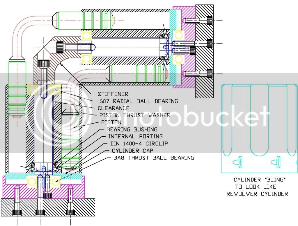
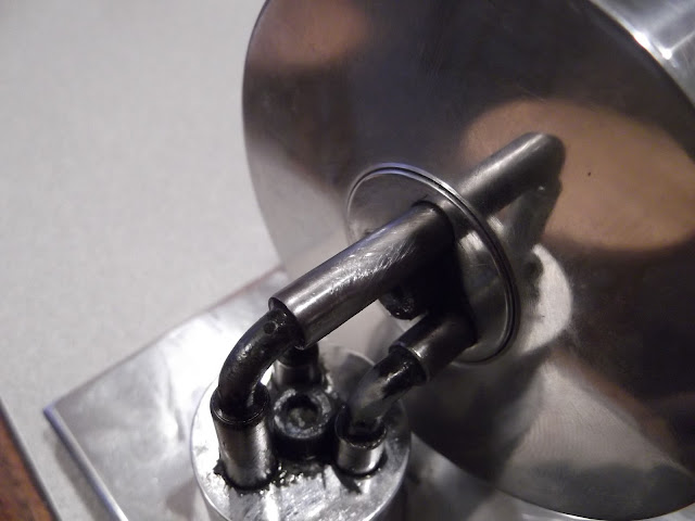
With a little tie on my hands this evening, I modeled a method of building the elbow cylinder so that air/steam leaks can be controlled and friction greatly reduced by moving the air/steam ports from the cylinder face to the cylinder shaft where it can be sealed with ordinary packing and by mounting the cylinder on ball bearings at both ends. Plain bearings could be used, but I believe that the radial loading imposed by the 90 deg bent axis would benefit from a ball bearing on the outer end at least.

I don't think that it is necessary to retain the cylinder on the shaft with a shoulder bolt or retaining cap as all of the axial thrust from the air/steam and the elbow mechanism is acting in the direction of forcing the cylinder against the frame.

The operation of the valve may not be obvious and the manner of plumbing the air/steam passages is not shown but it is simple and lends itself to incorporating a reversing valve quite easily. It is almost identical to the valve and plumbing on the Weeble engine in my avtar which is very clean running.If you want more detail, let me know.

Jerry

elbow cylinder with seals.jpg
 
Captain, Wow - thanks for going to all that trouble.

I was more concerned with the direct leakage from inlet to exhaust across the anulus interrupt - that requires a close running fit on the shaft - based on my experience with the improbability drive it worked fine - but if you get the slightest error in concentricity with the bearing it binds - so I would prefer to leave it running on the shaft and use thrusts at the end unconstrained radially to avoid concentricity / binding errors (although in the drawing below they are constrained ie a close fit on diameter - I've discarded that idea but haven't changed the drawing yet).

I dont think friction on the single 10mm stem is going to be an issue compared to 6 x 10mm pistons which don't rotate therefore they are tuning relative to the cylinder bores - by having them turn on the 4mm diameter shank of the elbows this will reduce that frictional component (and possibly permit piston "O" rings which then don't have to turn in the bore (relative to the bore).

In writing this I just realised that means the trust face of the piston is turning against the small anulus face of the elbow - I'll need to add an interference fit thrust washer there otherwise the elbow will ultimately burrow into the piston.

You have drilled your porting straight in and covered the redundant holes with the base cover - nifty - I have drilled mine from the inside out at an angle to eliminate the redundant holes - but it does put you close to the edge which will increase leak rates - so the base cover needs to be an exact fit - my intention is to bolt it on with sealant before reaming the centre bore of the assembly.

The idea of fabricating or machining the elbows from solid has also crossed my mind which for the moment shal remain a seething cauldron of ideas inputted by members as the design progresses and crystalises.

At this stage I'm thinking of drill rod for the shaft, aluminium for the cylinder, CI for the pistons and drill rod for the elbows. What would your material choices be ?

Thanks very much for the input.

My head hurts !

Regards,
Ken


DUMP1_Model.jpg
 
Ken

The model didn't take much time at all and it helped congeal some ideas that have been floating in the back of my mind. All of the axial engines that I have built have used a rotary valve on the shaft and I have also worried about loss across the intake/exhaust face but it has not been a real problem. I have fiddled with a milled annular slot on the shaft and also with simple milled flats. I don't see any difference in performance and the flats are so much easier.

You are correct about the concentricity problem with fitting ball bearings. Maybe not a good idea. I have another idea starting to take shape but needs some refinement.

I completely agree with your material choice.

Good luck with the project. A lot of people would like to see this work.

Jerry


It's quite a treat watching your fertile minds come up with some rather elegant solutions for the long accepted
issues with this engine. I'm sure many readers incuding myself are learning from this exchange and can't wait
for the final outcome.

Regards,
Mike
 
Ken

Here is my revised thought. Replace the Bearings with plain cast iron bushings which can be reamed in place to assure concentricity. The inner bushing incorporates the valve face. Improved fit and reduced wear on the valve face and reduced friction on the shaft. A shoulder could be added to the inner bushing to take care of end thrust.

This might be worth $0.025

Jerry

Elbow design w CI bushings.jpg
 
It is a fantastic little thing to watch run. But yes it does leak much air. I run my entirely on PTFE(Teflon) grease. A little squirt in the air inlet does the trick of lubing everything. Its a real lightweight grease

I've looked at your guys drawings and you come up with some very interesting ideas of directing the air to the cylinder, but I'm afraid you may be too focused on the wrong portion.

I had polished smooth my cylinder and valve port faces where they meet and it leaked so much air it wouldn't even run, Then I went back and sanded the faces flat again with 220 against a piece of glass. That cured all my problems and restored operation.

The air leaking from the valve port to cylinder faces doesn't seem to be an issue anymore, all off of my air leaks come from the pistons and the bores themselves. Its ran long enough that its developed a very interesting wear pattern on the pistons.

There may be some slight improvement to be made at the valving, but it definitely will not make the most difference
 
Captain, the bushes seem like a good idea to incorporate.

Rustyknife, the fact that yours wouldn't run right off the bat is what I'm actually tring to address - sure it works but requires a high degree of accuracy of a lot of fiddling to keep the valve face clearance to near zero. Since the entire cylinder diameter is exposed to this clearance even the tinyest gap is a major leak.

I would like to see a photo of the "interesting wear patterns" - the piston is going to follow a fixed motion locus all the while developing side thrust (to torque) so wear patterns will tend to accentuate - with a rotating piston this locus will become random and the wear should even out (might just be wishfull thinking on my part).

Similarly the problems with piston blowby can be accomodated with a piston ring or "O" ring - I'm not sure the engine will handle the extra friction but with a rotating piston (static relative to the cylinder) we might get away with it.

The whole purpose of the exercise is to do it differently (this might ultimately prove disasterous - but that's not the point) - as Dr. Phil says - if you do what you always do, you'll get what you always got !"

Thanks for the input.

Ken

P.S. loved your levitating motor.
 
Its an interesting wear pattern that's hard to take a picture of, best described as a crosshatching on a shaft, When you run it one direction, the piston raises in its bore, while starting to turn the cylinder and leaves a mark, as you run it the other direction it finishes the cross hatch.

DSCF0492.JPG


DSCF0493.JPG


Please ignore my paint coming off my elbows ;)

I'm liking the idea of the air introduced through the shaft more and more. It may prove to be a bugger, to set the timing the first time, but after you locked it into place, it should be quite the improvement
 
rustyknife said:
Its an interesting wear pattern that's hard to take a picture of, best described as a crosshatching on a shaft,

Have a similar pattern upon the pistons to my elbow engine. As the piston moves in the bore the cylinder rotates and whatever imperfection, burr, wart, or booboo that is in the bore leaves the corkscrew mark.

With as much as I use my compressor it could even be a bit of debri from the air line itself.

Robert
 
O.K. - the design so far :-
Elbow6.jpg


Since all the thrust will be backwards there is a thrust ball bearing - unconstained diametrically to the cylinder to prevent binding due to concentricity issues.
I have incorporated a bushing as per Captain Jerry's suggestion and a radial ball bearing at the top, the cyclinder then turns on 14mm of 10 diameter shaft (7mm ether side of the porting for sealing) the radial bearing at the top and the thrust bearing at the bottom.

I've added a hardened thrust washer to the elbow for the piston thrust face, this will either be a push fit or locktite to the elbows.

I am considering making a turning fixture for the elbows - they would still be bent from rod - but the 4mm piston running diameter would be machined in the fixture to get it dead square.

I have only a rudimentary flywheel sketched in at the moment - I'm hoping to build a motor that will run without it as I want to add some "bling" features to the cylinders to make them look like a revolver cylinder.

Hence the name "Six Shooter"

Sorry I seem to have Hijacked this thread so I'm going to start a new one.

Ken
 
Too bad you guys couldn't float the shafts on a cushion of air.
I used an air bearing fixture when I was a cutter grinder. Talk about low friction!!
 

Latest posts

Back
Top