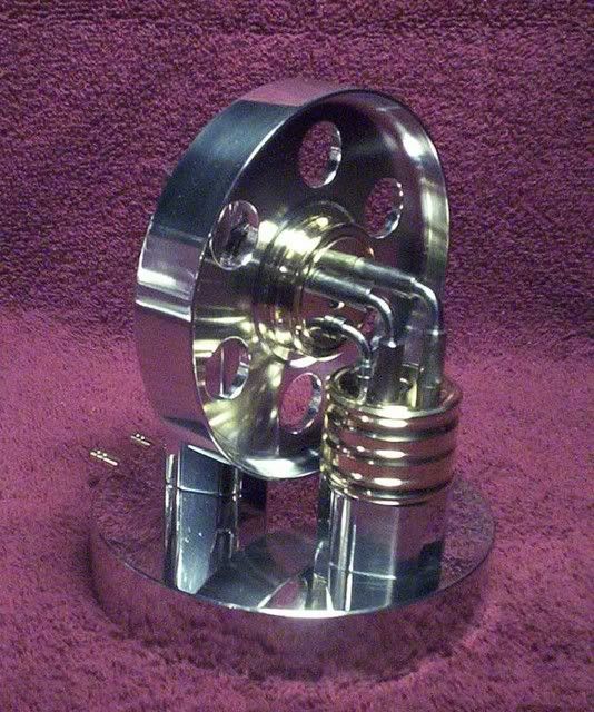
Elbow Engine leaks too much air.

Home Model Engine Machinist Forum

Help Support Home Model Engine Machinist Forum:

This site may earn a commission from merchant affiliate links, including eBay, Amazon, and others.

Rocket Man

Well-Known Member
Joined
Nov 4, 2011
Messages
240
Reaction score
121
I saw an old antique right angle drive at a Hit & Miss engine show it gave me an idea to build a 6 cylinder engine so I did. I found one on You Tube called an Elbow Engine so its nothing new. My engine runs but it leaks more air than it uses. I'm not sure if other people put air on 3 cylinders or all 6 cylinders but I have air going to all 6 cylinders. My engine probably needs some type of a seal to keep it from leaking I was wondering if anyone else has built one of these and how to keep it from leaking???

[ame]http://www.youtube.com/watch?v=GIvymk3OgOg&feature=mfu_in_order&list=UL[/ame]
 
What you are finding is nothing new I am afraid.

The design requires running clearances, and so you can only close up the gaps so much. This not only produces an engine that is air/steam hungry, but it throws any oil inside it everywhere.

BTW, it is not a true engine but by building it as one, it shows a right angle coupling that can be rotated through a full 360 degrees around it's input shaft. It is built as a concept of a Hobson coupling.

This is my one.

[ame]http://www.youtube.com/watch?v=5ZRKNlY7enM[/ame]


John
 
Hi RM

Like John said, it's an air-hungy engine and will spray around a bit of oil ;D

Experiment with different oils on it; they seem to like slightly thicker oils (which also helps with sealing).

Mine runs best if lubricated with 20W50 motor oil - any thinner and it starts to leak a lot , and any thicker and the oil starts adding too much drag and the engine slows down.

Regards, Arnold
 
Yes they are hungry for air, just as John and Arnold say.

They are definitely better with a sticky oil, I've found slidways oil is best, but engine oil is a close runner up, experiment as Arnold said to find the one that suits your engine.

Stew

 
Looks about how mine started up with a dash of oil in the line. Oil went everywhere and yes it is an air hog. Still is just so much fun to spin it by hand and watch the movement.

Robert
 
Mine wouldn't run well on oil.

I smeared the pistons with wheel grease and it ran great!

Rick
 
100_3120.jpg


Mine too uses alot of air and oil. I have a 60 gal. tank so I can hear it run quite a while with the compressor not running.

Kenny
 
I'm busy designing an Elbow Engine (pretty much complete to GA)
I would appreciate any suggestions from the experienced users above - as to possible improvements / refinements.

Ball bearings, labyrinth sealing grooves, anuli, "O" rings - whatever.

I want to incorporate a cylinder bottom plate so that the inlet hole is smaller than the bore and was thinking of a labyrinth groove / ring in the base to reduce leakage.

I've also considered making the "elbow" a sepparate part from the pistons - apart from introducing more play I haven't yet figured out why it won't work - but a small voice is telling me its a lousy idea.

Any comments or ideas will be apreciated.

Regards,
Ken
 
Ken here are some suggestions. I built my first engine with .250 pistons it did not have enough power to run. I changed it to .312" pistons with air to only one end thats 3 pistons it would barely run. Then I changed it so it has air on both ends so it is powered by 6 pistons now it runs good. I tried a shaft seal to stop the air leak but too much drag the engine will not run. I have my clearances at .001" it still leaks bad it uses a whole 10 gallon air tank in about 2 minutes maybe less. My pistons have a 1" stroke but not enough power for any seals I have tried. A tiny flat thrust bearing might be helpful under the head of each shoulder bolt.
 
If I remember right, Bogs and I talked a couple of years back about putting a radial needle bearing between the collared bolt heads and the cylinders. That would be a good way to keep the friction low and maintain minimal clearance between the cylinder and base. I haven't done it to try it out. The best tip I can give is my better half got a new cake pan after I built it. The engine blows oil when running and apparently I was not suppose to use her cake pan to set the engine in to contain the mess when running it.

Kenny
 
I remember that Kenny.

I suppose you could use small thrust washers like these ones, they are very cheap and are available in the smaller sizes we require. These are 3,4 & 5mm, but you can get slightly larger in this type.

Smallthrusts.jpg


One thing I did do with mine to make it easier to set up was to elongate the bottom valve holding bolt hole, the one furthest away from the standard. That allows you a bit of fiddle factor to get everything in their correct position for least resistance.


John
 
As well as the design Ken,

Think carfully on how you are going to make the parts, its important with this little beast that you keep everything square, and evenly spaced, I made two of them and learn't a lot with the first build and from talking to Bogs, when you make the cylinders make them together in one peice, and befor you split them mark them so you can assemble the cylinders in the same orientation that that were made.

Have a read of this

http://madmodder.net/index.php?topic=820.msg31361#msg31361

Stew
 
Thanks for the tips.

John, I had previously noted your suggestion to make the cylinders as one piece - good one.

I'm definitely going to add the axial thrust bearings.

Kenny my wife too has number of new "things" because of my useage - turbo vac, roasting dish (used as a reflector on a vacuum forming rig), preserve jars, spoons (used as forms) etc. etc.

It's easier to seek forgivness than approval. Although I haven't yet caved in to demands for a new oven for baking my sh1t in it. (I wait until she goes out - but have been caught red handed on more than one occasion).

Further comments or tips will be appreciated as this is definately my next project.

Ken
 
I have figure out a way to build this engine to reduce air leaks. The cylinder holes are not drilled all the way through. Drill and ream the holes to about .125" from the bottom. Drill air holes through the sides to connect the cylinder end to the center where the bolt is. Drill and tap the drill hole on the outside and plug it with a tiny set screw.

Replace the shoulder bolt with a soft metal bolt maybe a homemade bolt brass or steel. Drill an air hole up the center of the bolt about half way. Then drill a air hole out the side of the bolt so it will line up with hole for each cylinder as they come around.

Air can not leak out of cylinders with blind holes. When each cylinder comes around and lines up with the hole in the bolt it gets full air pressure. With no seals on the bolt it will still leak some air but the surface area around the bolt is several times smaller than the surface area at the bottom end of all the open end cylinders. Air leak should be very small.

 
That's a bright idea - but you need to make provision for the exhaust as well - I'll be giving this some thought.

A full through bore is just asking for trouble with leaks - so I was going to add a base plate with a smaller hole (so you can make both barrels as a pair - like Bog's suggested)

But an internal timing arrangement from the shaft might be just the ticket (see my improbability radial drive valvegear).

Any more bright ideas out there ?

Ken
 
Here's my partial redesign on the elbow engine.

I am introducing the air up the static spindle via an interrupted anulus (half inlet, half exhaust) - the cylinder barrel runs on this spindle & is mounted on ballbearing thrust washers either end.

Any vertical play will have no effect on leaks - only the running clearance between the shaft and cylinder barrel.

A seaparte plate bolts onto the base of the cylinder to close it off and still permit machining of both barrels from one piece.

I have added a right angle stiffener bracket between the two cylinder assemblies as I am concerned the shaft (held down by 2 M3 cap screws) might be a bit wobbly.

The pistons are free to rotate on the elbows, secured with circlips - if this works it will permit me to use "O" rings on the pistons and leakage will be confined to the running fit between the pistons and elbow shafts (the pistons will rotate on the elbow shafts rather than in the cylinders).

Any comments or suggestions ??

Ken

Elbow6.jpg
 
Ken

I have not built an "Elbow Engine" as commonly built so I may not be qualified to comment, but I have built this a few years ago:

"http://www.youtube.com/embed/hOOzFG1canw"

It uses a valve much like the one that you show and I think that is the way to go. The usual design that puts the valve face in the base seems to invite leaks as the air pressure wants to lift the cylinder off of the base and is difficult or impossible to seal. By putting the valve on the shaft it can be sealed with a gland or an 0-ring.

The rotating pistons seem like overkill. I don't know why o-rings can not be used on solid pistons. Won't o-rings rotate as well as slide in the cylinder bore? My chevron engine was quite leaky as well and most of it was piston blow-by. It did not use any rings on the piston. At the time that I built it, my equipment was limited and my experience was non-existant. If I were to build an "Elbow", I might try using teflon for the piston which would be fixed on the elbow.

To me, the real challenge is producing four (or more) exact (or at least identical) bends so I ight think of some way to fabricate the elbow other than bending.

$.02

Jerry

 
Hi Ken, I'm glad to see someone finally tackle the problem that has been a scourge to this engine for quite some time now. In the very back portion of my mind, which is usually cluttered with similar fleeting ideas, I always had it that a better way of sealing the leaks was possible but never pursued the notion much. I'd be very interested to see your solution as it seems to be well thought out and relatively easy to execute. Doing away with the one piece piston assemblies is a blessing as well. Good luck

BC1
Jim
 
Captain, Thanks for the comments.

I don't actually intend to use "O" rings - but I will provide a groove for them.
"O" rings don't survive rotary applications - there is no lubrication mechanism so they run dry, hot and melt (you can get away with it in slow rpm applications) - the elbow engine would be rotating and sliding at the same time so it will lubricate and will probably work.

From what I've read, friction is a killer on these beasties - another reason "O" rings might not be a good idea - however I'm hoping to work around as many possible problems as possible with the redesign.

The extra work of the "loose" pistons is not that big a deal and if the bending goes all pear shaped, I only have to remake the elbow portion.
You are right the elbows are the killer - I'm thinking of making a press tool to form them in a mechanical press as a production job - starting out with plain rod and going for the turned parts only once the 90° is spot on.

Also machining two pistons and the elbow as one piece is problematical in steel in that the material at the centre of the bar (particularly from continuous cast source stock) is very coarse grained, suffers badly under fatigue and cracks far more easilly under bending.
The "loose" pistons will also allow the use of different materials like CI pistons and groundbar for the elbows (whatever).

Bearcar, I'm hoping someone is not going to point out a blindingly obvious flaw in my logic - but then that's the whole point of the post. I'm no elbow engine expert (a year ago I didn't even know such a thing existed).

Regards,
Ken

 
Ken

I think you are right about two part elbow/piston. I just don't think the piston needs to rotate. A good fitting CI piston with bent rod seems like the way to go. Have you considered any other way to fabricate the elbow?

I have seen some suggestions that a thrust bearing under the head of the center bolt would reduce friction but it seems to me that there is zero thrust in that direction if eliminate the face type valve and use the shaft valve that you show. It seems to me that the friction problem is the length of the center bore riding on the shaft and the side load that is put on that by the elbow. That could be eliminated with ordinary radial ball bearings and seals at BOTH ends of the cylinder.

In the interest of making a quick reply, I have not modeled the whole design but this is a quick 3D section of the cylinder with bearing seats at both ends. It doesn't incorporate a through bore and a sealing end plate, which is a good idea but that could be worked out.

Jerry

Elbow Cylinder.jpg


turned elbow.jpg
 
Back
Top