Dyna Myte 2400

Home Model Engine Machinist Forum

Help Support Home Model Engine Machinist Forum:

This site may earn a commission from merchant affiliate links, including eBay, Amazon, and others.

d-m

Well-Known Member
Joined
Mar 20, 2008
Messages
211
Reaction score
5
OK I have been bitten
About a year ago I was Visiting with Mike at Mini Machine http://minimachine.com/
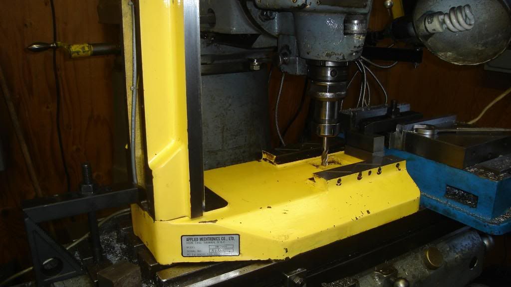
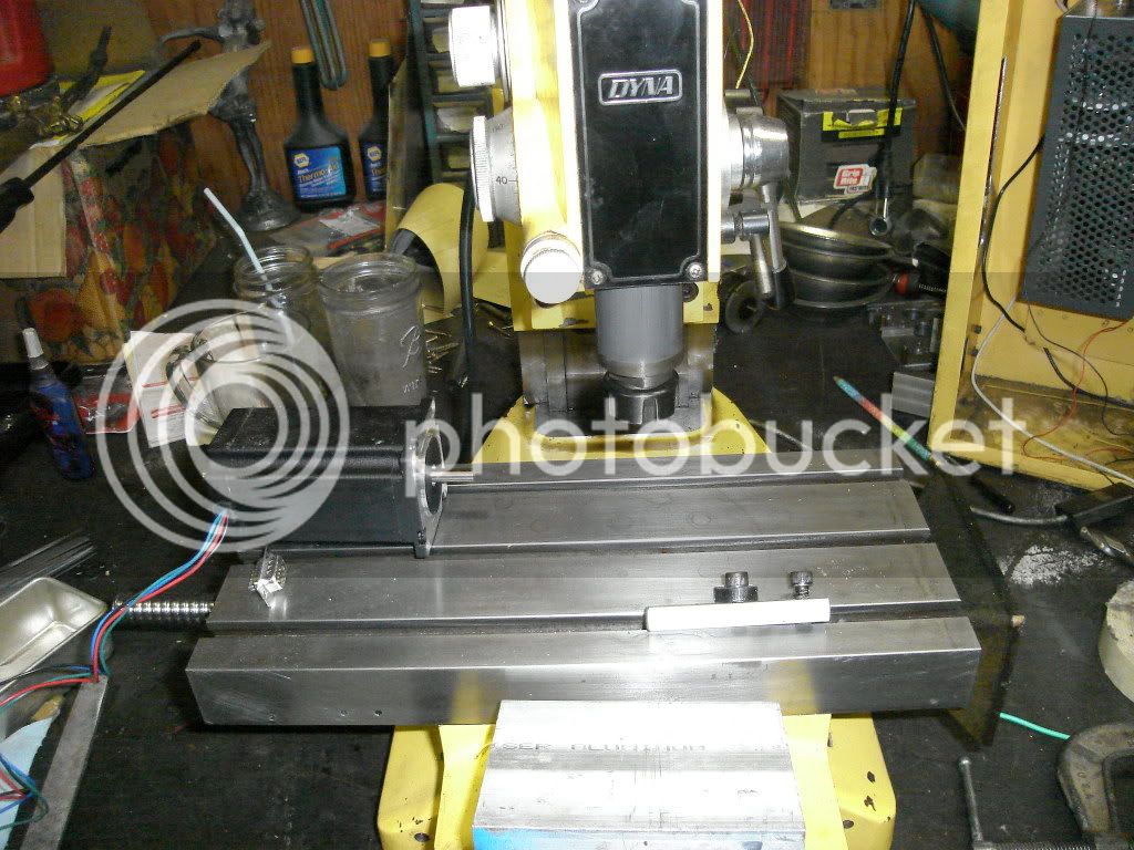
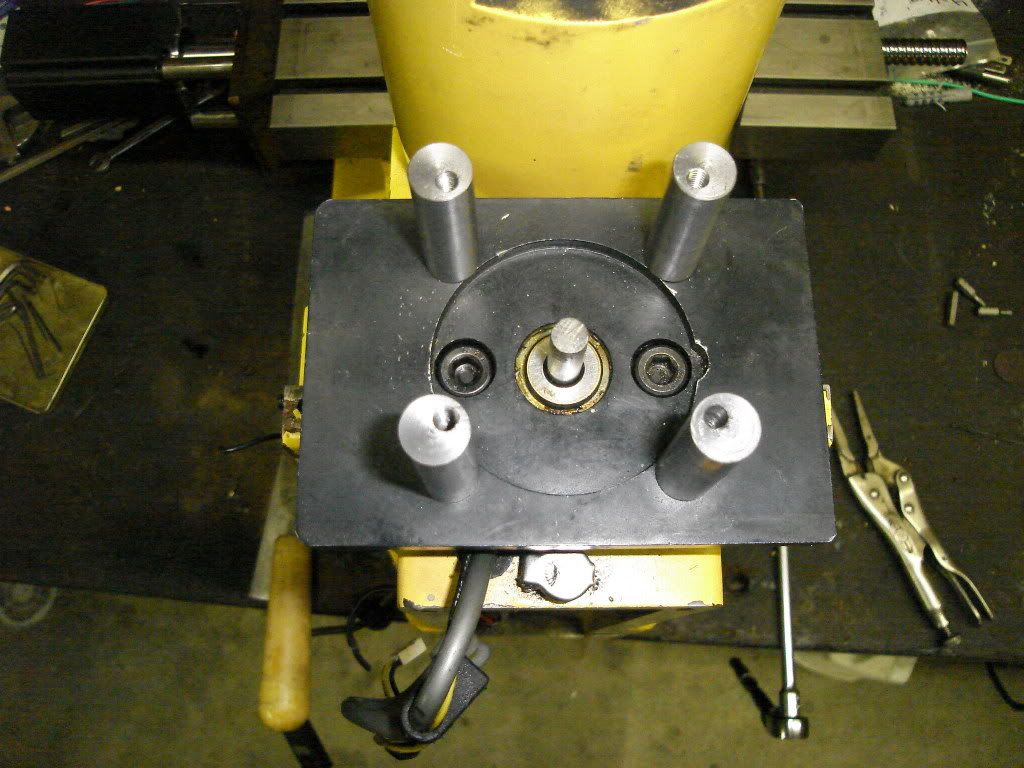
Mike had a Logan lathe at home for sale and wanted to know if I was interested. The next week I rode out to his home to look at the machine. It was not what I had in mind but there were some other things he had that he was selling and one of them was a Dyna Myte 2400 mill. Long story short I made a deal on the mill as money was short and he was in no hurry to get it out of his home shop it has sat for a year. Last week it made it to my shop, being in the middle of a vary large camper van project I had time to unload it and did not get a look till last night. The X and Y drives have been replace with with handles the gears in the housings are gone along with the motors but the Z axes is intact. The mill is like new but dirty the power supply's are in the box as is the control board the control head is gone.It all powers up and the spindle motor runs nice and smooth and the speed control works.I was surprised to see the z axes motor was 27 oz but then i found the gear reduction and wow I bet it was slow but had a lot of grunt. So here starts the beginning of my CNC Mill I need advise at this point on the X and Y do I try to find the stock parts or go with new motors and belt drives?
Let the games begin
Dave
 
Try to determine if you can what parts are good and what parts need to be replaced. then contact the manufacturer and determine price and availability of parts. If price is too high or parts not available just treat it as a retrofit and start from sort of scratch. it was built as a cnc you should have an easier time.
general rule of thumb servos are belt driven steppers are direct drive.
This thread was written for conversions it may help
http://www.homemodelenginemachinist.com/index.php?topic=9787.0
Tin
 
That will make a very nice NC machine! Build a coolant tight box with a good sized door and set that machine right in the middle - perfect! Flood coolant it the way to go and most folks (like me) think of that as an afterthought.... From the start you can be making your drives and wiring moisture tight.

Just a suggestion - and I wish I had thought of it at the very beginning. Makes a machine almost totally autonomous by washing the chips away while keeping the work and cool tool cool....... ;D

BillC
 
Thanks Tin
I have read you thread on whats needed a few times now. You know how it is when its new its a learning curve. I have done some looking around and I believe that these machines were sorta slow (not that it should matter it is a hobby) and with the missing parts I have decided to go with a refit of the X & Y and am looking into using the Z axes set up as is. There was a control board on the Z motor and the bank of transistors on the board have overheated. I also will need to find out if I can use that 8 wire stepper with like a gecko stepper driver. I am vary lucky I have a friend close by we do a lot of projects together and he is vary good with electronics he is working on a control board (stepper board) for one of my wife's embroidery machines so I have back up on that end just around the corner.
Bill
That was the one thing that came to mind as I was looking at it on the pallet it needs a good coolant box and some flood this machine should be an easy redo as I wont need to fit ball screws right away. the machine is very dirty and a good cleaning will help I looked at the backlash on the X axes Saturday evening and its less than 1/2 thou. And I remember Mike told me the backlash is adjustable on the screws. Ill keep reading and learning I have a few projects I have to get out of the way this camper van and a craftsman 109 lathe overhaul.
More to come
Dave
 
You may also want to check out the CNC zone and Mach III support forums. The dyna mite name has come up in cnc seminars I have been to . a fairly common name in cnc I would guess. You are not likely the first gut to restore one.
Maybe you can find someone who has been there and done it on one of the above forums.
Tin
 
My last post generated no replies I had to make the choice on my own no big deal the budget is the final answer anyway ( and its slim ) . I ordered up the ball screws from china after taking some measurements I picked screws that were longer than I needed by about 2" for each axes. The nuts were .155 to tall to to clear the hollows in the bed ways. I had anticipated this knowing I had a surface grinder I could use. Here are some pics of my progress so far fitting the screws.
This pic shows the base set up in the mill there is a pocket that the original screw sat in it had stands cast in it that had to go .I knew the cuts would be light and I am lazy and did not want to re square my vise (hence the shaky set up)
DSC03255.jpg

The next pic you can see the stands.
DSC03257.jpg

And all cleaned up
DSC03260.jpg


This pic shows the nut and screw in the pocket this is were I made my mesurments before grinding down the nut.
DSC03263.jpg


And with the nut ground off .150
DSC03266.jpg


I got home and set the nut in the pocket the Y axes had some rough casting matter at one end it was just some slag but it was interfering I got it on the mill vise and started to knocked it down
DSC03268.jpg


that's when the dinner bell rang so that's it for this post.
I will try to continue this if there is interest in the build.
Dave


What are you using to anchor the ball screws? Duplex angular contact pair? or something else?

Dave
 
Steamer
I think I understand your question, correct me if I'm wrong the ball nut will be mounted in the pocket with a fab up bracket button head screws will secure it through the bottom.
On this mill there are front plates with a bearing pressed into it a shoulder is machined into the ball screw that goes through the bearing and it is loaded with a spacer and nut.

Dave
 
d-m said:
Steamer
I think I understand your question, correct me if I'm wrong the ball nut will be mounted in the pocket with a fab up bracket button head screws will secure it through the bottom.
On this mill there are front plates with a bearing pressed into it a shoulder is machined into the ball screw that goes through the bearing and it is loaded with a spacer and nut.

Dave

Hi d-m


"And is loaded with a spacer and nut"... That's what I'm looking for. OK that makes sense, a preloaded duplex pair of angular contacts would be expensive, where a pair of unmatched bearings and some shims is very inexpensive , albiet time consuming to put together. I am talking about the stationary bearings that take the axial screw thrust loads.

Dave
 
Well after getting the Y axes bed cleaned up I started finishing up the ball screw mounting Not a lot of magic here some 6061 angle hack it to size BLAH BLAH BLAH.Find my centers cut a pocket and drill some holes
DSC03303.jpg

install screw and check fit even with some shaky measurements at best the ball screw end slid right into the bearing no shimming necessary and when I set my electronic angle finder on the screw it is 0.00
DSC03302.jpg

The nuts were to hard to tap for screws so I dug up some 5mm socket heads that fit the hole but loose I chucked them up and cut a shoulder on the bottom of the head so it would center the nut
DSC03305.jpg

And yes machining the ball screw is a PITA but it came out perfect
Next weekend is a zoo trip to Portland on Friday should have a few hours to start on the X axes.
Dave


Hi all it's been a few weeks so I thought I would post an update on the mill conversion. The Y axes was a mirror of the X and is done. I had a project come in after the Y axes that took that week and some of last weekend so I started the Z axes Friday.This one is a bit more fussy than the other 2 unfortunately I failed to take a shot of the before. But the pic will make it clear what I decided to do. in the first pic you can see were I milled away the top of the column the reason was (and it was a hard one to make) was that there was no way to install the screw. I looked at removing the nut and loading the balls with the screw in the column but that seemed to add to the problems the nut has a plug but the plastic was injected + the issue of trying to load the balls into the nut in the column.
DSC03515.jpg

The area I removed was rather thin to begin with .130 and there is a lot of meat in the rest of the column and I think it will be OK.
DSC03511.jpg

In this pic is the slide the nut was .190 too big and not wanting to spend the time to grind it I machined out the area that was interfering.
Thanks for looking
Dave
 
Hi Dave, Thanks for sharing your retrofit. I have been contemplating doing my own and I will be watching your progress. Dave
 
Hi All
As I said in my last post the Z axes is a little trickier than the other 2 and here is some shots that show why.

In this shot you can see the area to work in is small.

DSC03515.jpg


And this is the plate I made to fit the nut as you can see it 1/2 a plate
here are the mods made to the lower plate

DSC03535.jpg


DSC03529.jpg


And this is the beginning of the other half The issue is there is not enough room to put a one piece bracket in and with the ball nut so it was necessary to make it in 2 half's sorta like a rod end.

DSC03536.jpg


<a href="http://s1134.photobucket.com/albums/m603/dromsdhwi1/?action=view&amp;current=DSC03530.jpg" target="_blank"><img src="http://i1134.photobucket.com/albums/m603/dromsdhwi1/DSC03530.jpg" border="0" alt="Photobucket"></a>

DSC03542.jpg


Here is the other half almost done
If you wanta look at the rest of the pic's go to my photo bucket

http://s1134.photobucket.com/albums/m603/dromsdhwi1/

and one more shot of the modified plate

<a href="http://s1134.photobucket.com/albums/m603/dromsdhwi1/?action=view&amp;current=DSC03530.jpg" target="_blank"><img src="http://i1134.photobucket.com/albums/m603/dromsdhwi1/DSC03530.jpg" border="0" alt="Photobucket"></a>

Dave
 
Hi all
Wow I cant believe how much time has passed since I last updated this thread. But as normal in my house and shop things have been more than crazy my side work load has been time consuming. But winter is here and I will only do inside shop repair stuff till spring. So on the CNC project I ordered up a Gecko 540 drive and 3 steppers I have the wire and the material to make the mounts. I left off fitting the Z axis I thought I had it all worked out just fine till I did the final assembly and realized the bottom end of the ball screw needed a support it was rubbing the bottom of the casting and wasn't smooth. With no room to machine a bottom for a bearing, I did the only thing I could think of I chucked up the ball screw in the lathe carefully drilled a center and then enlarged that to .250. Then using a ball end .375 end mill I drilled/ bored it to.187 this allowed me to insert a hardened steel ball in the end. Then with my dremel and a burr I smoothed the bottom of the casting. Using a scrap of 5/8 bar I machined the recess for the ball making a few quick bushing for a guild I dropped the rod down the casting and gave it a rap with my trusty BFH. That give me a ideal of were the bearing would sit I did my best to make a nice divot for the ball to rest in and presto a bearing for the bottom of the lead screw to ride in. I failed to take pic's but here are a few of the finished mill and Z axis screw installed you can even see that there is a small well that will hold some oil to help keep it lubed.
DSC03625.jpg

DSC03624.jpg

DSC03623.jpg

DSC03622.jpg

Dave
 
Time for an update.
I spent the last few weekends working on the motor mounting lots of ideals but KSS (keep it simple stupid) is always the
easiest way right? Well not without a few challenges, first was the motor stands the original bearing plates were drilled and taped
4mm but did not line up with the new motors. Using some .500 drill rod cut and faced to length drilled and taped 4mm. Then a plug was made to fit the bearing and the motor shaft to keep things lined up. Then a transfer punch was used to mark the motor end of the stands. I then took them to the mill and found the punch mark drilled and taped X 12.
DSC03643-1.jpg

This past weekend I worked on the coupler I decided to use the split cotter design for a good nonslip connection. So with some 1" round stock in a collet I brought it to size .812 drilled through and reamed one side at 312 and the other at .250.
With that out of way it it was off to the milling machine taking my best guess I cut the notch and had my first piece for the scrap box but from there I knew were I was going. I set the quill depth at .170 and off set from center .150 and made the cut.
DSC03649.jpg


The next step was the the cut I learned from the piece that now is in the scrap pile that the portable bad saw wont make a nice straight cut so I opted for a end mill for two reasons one nice straight cut and second I needed a way to keep it flat for drilling the holes and taping.
DSC03652.jpg


DSC03654.jpg


DSC03659-1.jpg


DSC03660.jpg


I normally don't have any issues with taping holes even these huge 4-40 ones but there was one hole that gave me trouble and I broke a tap from there I just got a good straight thread started as shown and finished on the bench taking my time I could have turned the part over and milled a flat were the tap was going to come out on the bottom and it would have saved some time but it was fun to try to get this way and it looks cooler.
DSC03662.jpg

DSC03644.jpg


All that's left here is to trim the 4-40's to length and I was impressed how little I needed to snug the bolts up to get the squeeze on the shafts.
So next will be the wiring and setting up the PCU in the shop I have all the supply's and 2 weeks off for the holidays bet you cant guess what I'll be doing
HAPPY HOLIDAYS ALL
Dave
 
Nice work Dave!

Any ideas on your first project when this is all done and working?

Andrew
 
Andrew
Thanks for looking
To answer your question I really haven't thought about it much but I think the day I put a hunk of material on the bed and program it to cut a straight line and it works Ill be doing the happy dance big time!! I do have plans for a sterling water pump I am itching to build and this would be the ticket for the base and stands. I have a ways to go before I get there but Ill keep this in mind as I go.
Dave
 
Back
Top