Dividing head for Taig lathe/mill

Home Model Engine Machinist Forum

Help Support Home Model Engine Machinist Forum:

This site may earn a commission from merchant affiliate links, including eBay, Amazon, and others.
Hi all

In between some honeydo's and going to work, got some more done....

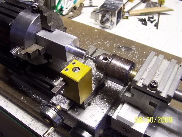
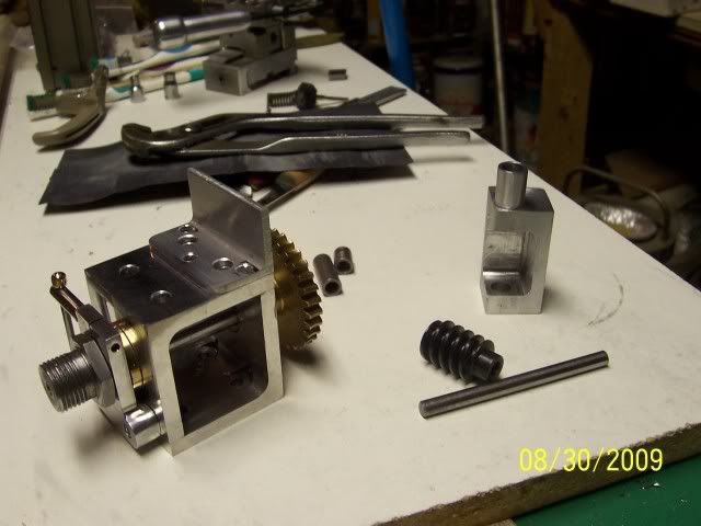
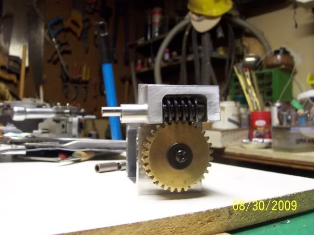
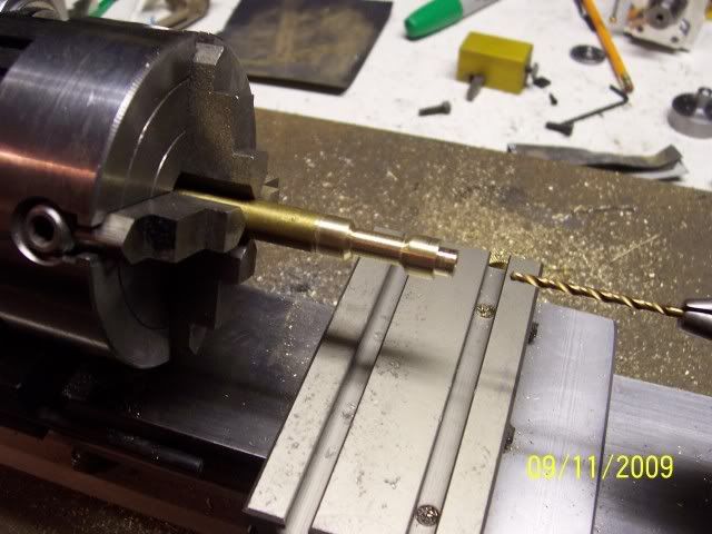
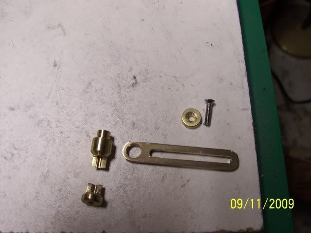
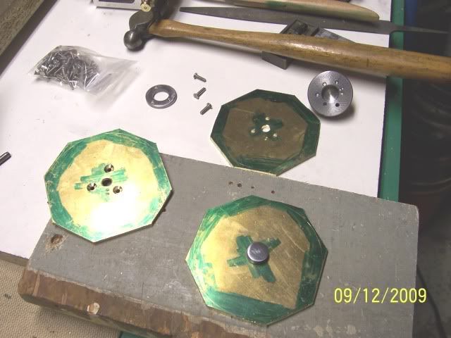
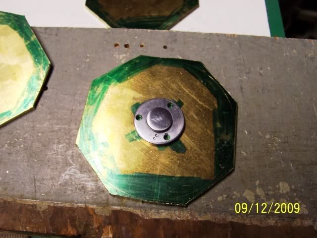
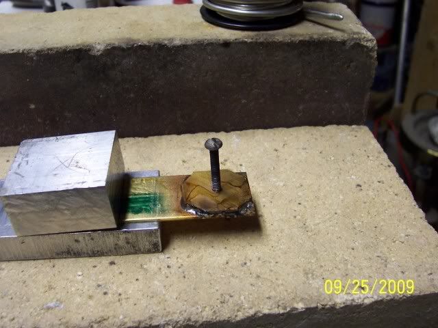
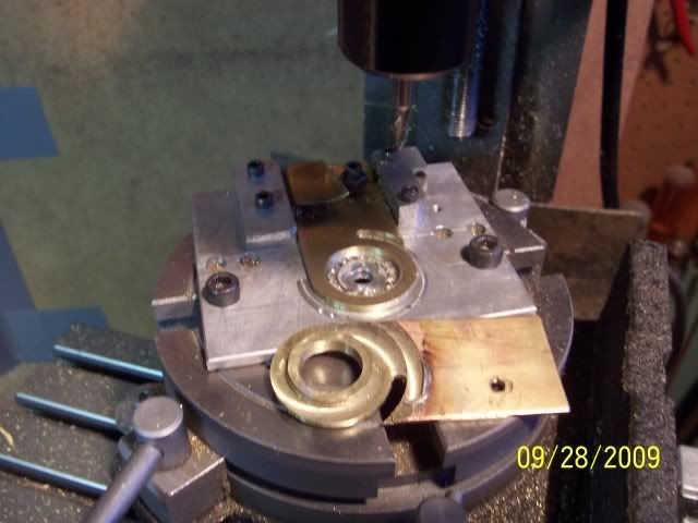
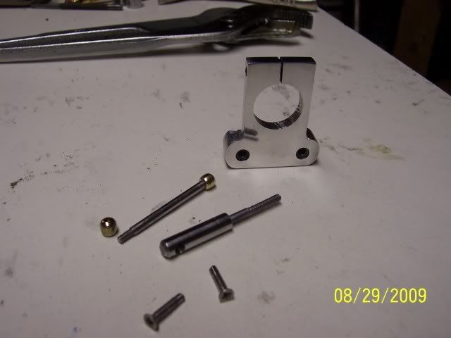
parts for the spindle brake:
100_2189.jpg


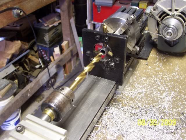
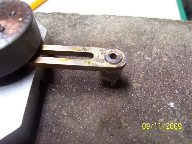
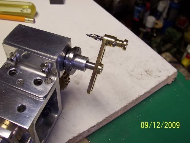
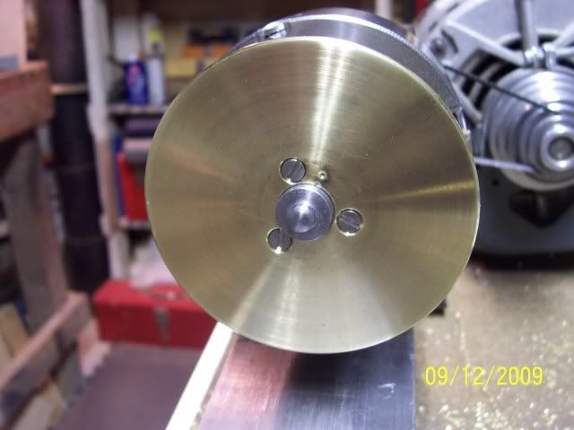
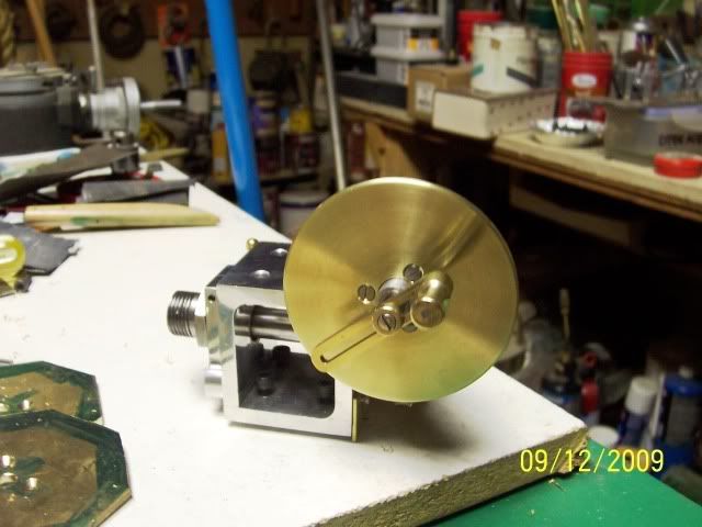
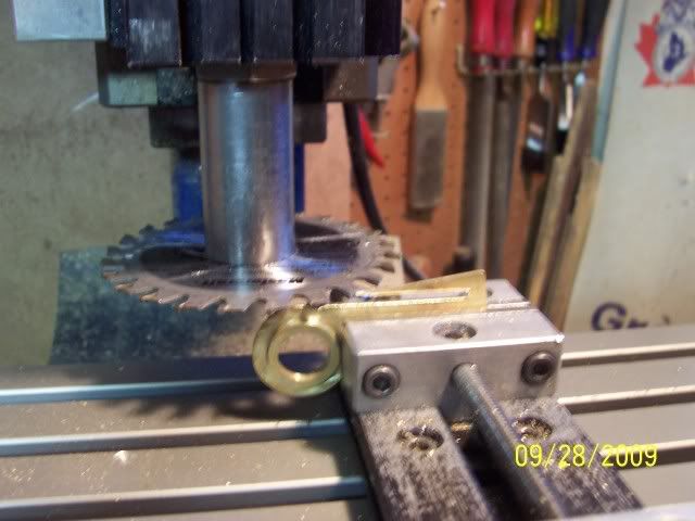
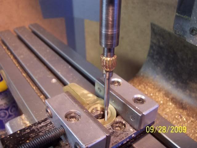
and then installed where they belong:
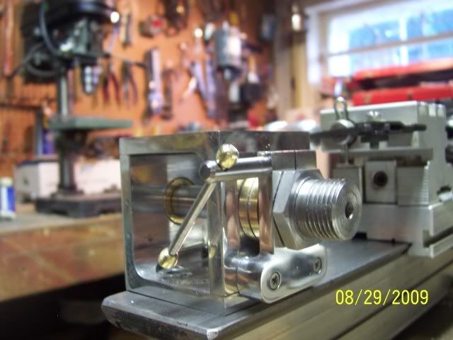
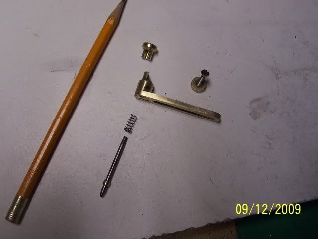
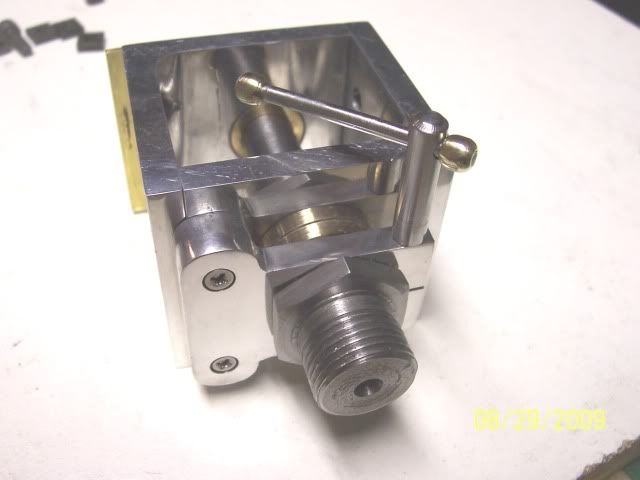
100_2191.jpg


from another angle:
100_2192.jpg


Didn't take any piccy's of constructing these parts, it was all straight-forward milling & drilling.

Joe
 
Got to work on the worm carrier

Needed an off-set boss on the part: no problem with the 4-jaw, but had to add a temporary dead centre (bit of drill rod with a taper on the end) in the drill chuck on the tailstock to leave enough room to move the carriage
100_2194.jpg


Then use the steady rest while drilling and reaming for the gear shaft
100_2195.jpg


then a bit of straightforward milling to form the pocket for the worm
100_2196.jpg


And here it is sitting where it belongs...
100_2197.jpg


Still got a little cleaning and polishing to do, add the oilite bushings, drill and tap some mounting holes....

A question for the learned: what's the received wisdom for attaching the worm to its' shaft: setscrews or through hole and roll-pin?

Cheers, Joe
 
Looking really good, Joe. The brass bobs on the end of the brake handle are a nice touch. Good work.

Dean
 
:bow: :bow: :bow: very nice Joe, have you finished all your honeydo's :big:


Regards Rob
 
Thanks, Dean. Rob: Honeydo's are like mushrooms.... pick one and a multitude spring up in it's wake :big: ( I know how Sisyphus felt.....)

Joe
 
Hi all

Got some more done...

Made a bit that goes on the worm carrier spindle to hold the actual indexing plate, no photo of that, it was simply turn, drill, tap, and part off. Then got on with something a little more interesting, the plunger and arm...

Turned a bit of brass, allowing enough material in the narrow centre bit to arrive at the desired dimension after parting, drilled all the way through with a No 43 bit for tapping 4-40, then opened it up with a 7/64" to just shy of the knob as clearance for the drill rod plunger.
100_2202.jpg


Made the arm, some straightforward milling and drilling, parted off the brass bits that become the plunger knob, filed matching flats on the top and bottom parts..turned the c'sunk washer that will hold it on the worm shaft
100_2203.jpg


Nothing special here, but I had to post a pic of the BEST silver-soldering job I've ever done!
100_2204.jpg


Here are all the parts ready for installation: The plunger is a little bit of drill rod, threaded 4-40 to fit the top knob, a little brass piece soft-soldered in place as a retainer for the spring, which was culled from a ball-point pen
100_2205.jpg


And here it is where it belongs.....
100_2207.jpg


Nearly done now, just need to make some brass disks for the plates

Cheers, Joe
 
Thanks, Zee.

Was able to get back out in the shop after supper, so things have moved right along...

Cut some blanks out of some 1/8" brass, drilled a 1/4" hole more or less in the centre for the little button you see that locates the drilling guide for the mounting holes...
100_2209.jpg


Here's the drilling guide, notice the witness marks, they match the ones on the mandrel I made for turning the blanks, and on the bit on the indexer where the plates are mounted. All these parts were drilled (clearance or tapping size) in the same set-up, so any errors of location will be consistent at least!
100_2210.jpg


Dialled in the mandrel in the 4-jaw, less than 1 division TIR
100_2211.jpg


Turned to size, and here you see that little button back, it's also a plug gauge for the bore to fit over the spindle on the worm carrier...
100_2213.jpg


And....

Ta-dahhhh
100_2216.jpg


Two more to finish, and then some holes to drill....

Cheers, Joe
 
This is a great thread. I'm really enjoying it. :bow: :bow:
 
Coming along very nicely Joe great looking bit of kit :bow: :bow: :bow:

Regards Rob Thm:
 
Nice ..... Very nice :bow: :bow:
that rearlly does look the biz

but I dont envy you will all that drilling to go

Regards
Andy
 
Vernon, Rob, and Andy:

Thanks for your comments. Andy: I'll bet that deep-down, you really DO envy me drilling all those holes... so, I could send you one of the division plates so you can have some of the fun too.... :big:

Thanks again guys,

Joe
 
Really starting to close in on the end of this project...
made up the sector arms

soldered on a bit brass to form a hub (first try with this new-fangled lead-free solder... works just fine) used a dirty old screw that solder won't stick to for locating the parts
100_2225.jpg


set up on the rotary table with two arms stacked, formed the hub, milled the central hole, rounded the end, the took off the arm with the hub to open up the centre hole on the other arm to fit the hub.(this is where I was several days ago, when I learned that I had not clamped things down well enough. Oh well, the scrap bin was getting low....)
100_2226.jpg


Sawing off the bit that doesn't look like a sector arm...
100_2228.jpg


Set up in the mill to drill and tap for the retaining screw (Using my "Marv Klotz Inspired" sensitive tapping device)
100_2229.jpg


And here we are where we belong. Try to not notice that apparently both 89 AND 90 degrees need a "ten unit" indicating mark on the protractor... only buggered it up once in 360 divisions :wall:
100_2232.jpg


Cheers, Joe
 
Brilliant work Joe ;D

I'm with Andy though, I don't envy you all that drilling :(

CC
 
very nice Joe :bow: :bow: :bow: great job ............. you will have to make a nice oak box to keep it in ;)

Regards Rob Thm:
 
CC: Thanks, mate. Sorry it took so long to reply.

Rob: Either you're a mind reader or you've been paying attention to the contents of the last PM.... :big:

As a general note of progress: 2 dividing plates all drilled, two to go, and

(WARNING: Mature Subject Matter, not suitable for all audiences
I've started fitting up a box out of that brown organic stuff AKA wood :hDe:

Cheers, Joe
 
This is great work, well done.

I also built a dividing head on my Taig lathe using Tony Jeffrie plans, at the time I had access to a large mill at work, so used a solid ali block.

Unfortunately, due to HSE regs, I am not allowed access to the machine shop tooling any more, so I am in the process of buying a mill for myself.

Anyway, here are some pics of my dividing head and some gears I cut using 0.5 mod cutters.

Ian

IMG_1208.JPG


IMG_1209.JPG


IMG_1210.JPG


IMG_1212.JPG
 
Looking really good! I've been thinking of doing something like that myself, but I just cant find the time anywere! ;D Really! I've looked all over the place... But no time at all! There is always something else that need to be built first! Hehe
 
Ian: That turned out nice. I've got a taig mill, so cutting the base out of a solid chunk would have taken a long, long time!

Mads: If you find any of that time, send a bit my way please! Any time I find any here, my wife has me painting another room....

Cheers, Joe
 
joe d said:
Any time I find any here, my wife has me painting another room....

I think most of us have that Tee shirt Joe ;D .............. nice to hear your progressing though, the brown stuff ain't all bad btw :big: ;D :big:

Ian ..... again ....... nice work ;)

CC
 

Latest posts

Back
Top