cutting internal keyways?

Home Model Engine Machinist Forum

Help Support Home Model Engine Machinist Forum:

This site may earn a commission from merchant affiliate links, including eBay, Amazon, and others.

mnewsholme

Member
Joined
Jul 24, 2008
Messages
20
Reaction score
0
Hi all

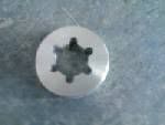
I've got an X3 mill and it doesnt feature a spindle lock. Normal method is to make a pin spanner to engage on a couple of holes on the bottom of the spinde but this is a bit awkward to use. The top of the spindle consists of a 20mm shaft with six equidistant 4mm wide by 2.5mm square splines on it. I'm making a knurled disc with the appropriate hole in the middle to drop over the shaft and give me something to grip when undoing drawbar. Making it as a disc rather than a spanner with thought that if I forget to take it off before staring up it wont go flying across shop.

I've got the disc made and the 20mm hole bored. I need some ideas how to cut the keyways. I've got a rotary table and obvious thought it use this to index the disc and mount a tool in mill spindle and use quill movement to shave the keyways out. Problem is lack of a spindle lock to keep the cutting tool in the correct orientation. obviously this would be done with power off.

what I'm thinking of doing is mounting disc in three jaw chuck on lathe and mount a appropriately ground tool in toolpost and using carriage travel to make the cut. I'd use a bar clamped to the saddle and push the jaw off the three jaw up tight against it to index the chuck. This would create 3 keyways 120 degrees apart. Then I loosen three jaw and rotate disc and move crosslide back so tool picks up one of alread cut keyways whilst jaws are tight against the bar on the saddle and re-tighten the chuck jaws. this should give me correct disc position relative to chuck jaws to but the remaining 3 slots.

Does this sound workable? material is aluminium.

If anyones got any blindingly obvious simple way of doing this that I'm overlooking I'd love to hear it.I'm trying to do it without having to make up extra tools to do the job first if I can avoid it. Wont have chance to try it till weekend anyway.

cheers

Matt
 
Do You also have a lathe? (edit, missed the last bit, you do)

If so use a boring bar with a HSS toolbit in it, cutting edge vertical and use the saddle to plane out he groves, spacing the groves by indexing the spindle. Using the quill feed on the mill will put a lot of load on the rack

Did the four grooves on the following part that way. 3/16 wide grooves in steel 1" long, about 0.001" at a time
A7-2ndShaftGears.jpg


Jason
 
hi jason

forgot to mention that when i said mount it in chuck I meant chuck on lathe. ::)
I'll edit post to say that. Seems like i'm on right track though :)

cheers

matt
 
Can't use a socket like that as you need to get at the hex end of the draw bar that sticks out the end of the splined shaft

Jason
 
There is no law that says the bottom of the grooves has to be square. You probably have plenty of metal as the disc will be large enough to hold on to so I would just mill the grooves using the rotary table and leave the bottoms of the grooves round. It is not like you are transmitting high speed motion. It's a wrench.
Gail in NM,USA
 
GailInNM said:
There is no law that says the bottom of the grooves has to be square. You probably have plenty of metal as the disc will be large enough to hold on to so I would just mill the grooves using the rotary table and leave the bottoms of the grooves round. It is not like you are transmitting high speed motion. It's a wrench.
Gail in NM,USA

yes I could do it that way but I dont have any milling cutters smaller than 8mm and I'm trying to avoid having to buy a cutter and wait for delivery for such a simple job. I've got lathe tool blanks and I can grind a keyway cutter tomorrow.
thanks for reply though

matt
 
Matt
I have the same mill here and have been thinking on the same problem. My current line of thought uses a flat piece of aluminum with a "C" cut into it to fit the splined shaft, like the crescent wrench I've been using. I'm thinking I can mount it on top of the lathe and use a lever of some sort to engage and disengage the C. I would be spring loaded so it doesn't stay engaged when there is no pressure on the lever.

I haven't modeled it out yet, but do have a fair "mental image" of where I want to go. Feel free to use the idea if it suits you. I'm not quite ready to make the thing myself, just yet.

I hope you're enjoying yours as much as I've enjoyed mine so far. It's a work horse.

Steve
 
mnewsholme said:
yes I could do it that way but I dont have any milling cutters smaller than 8mm and I'm trying to avoid having to buy a cutter and wait for delivery for such a simple job. I've got lathe tool blanks and I can grind a keyway cutter tomorrow.
thanks for reply though

matt

If you haven't bored out the center of the disk yet, use a drill to drill holes around the periphery of your circle. Then you can bore it out. You'll have nasty interrupted cuts doing the boring, though.
 
Matt,

If you have bored the centre, make a plug at 1:1 fit, drill the holes as Kevin suggests and knock the plug out, leaving half a hole in the body.

If you still want a square bottom that's fine, but most of the works been done and far less stress on your lathe saddle and rack, (not to mention your hands and arms ::)), than going the whole distance square 0.005" at a time.

Hope this helps ???

Regards
Bob
 
Matt,
Why not file the keyways? A pair of dividers set to the radius of the disc will neatly step out six divisions on the circumference. (Well 2*pi divisions to be exact, but who's counting?)
Filing 4mm*2.5mm keyways in aluminium will be alot quicker than trying to use your mill or your lathe as a shaper and taking off .001" at a time.
Not eveything has to be done using machine tools, but I guess to a man with a hammer, every problem looks like a nail. I'm guilty of this myself.
 
I just did a keyway today on the lathe. I needed a 2" V groove pulley for a machine and for the sheer
fun of it, turned one out of a peice of stock. For the keyway I ground an angle on the end of a 3/16
HSS tool bit and did the back and forth bit with the carriage taking about .005 per pass. Worked a
charm. Only problem was I was working in a blind hole so had a bit of trouble breaking off each chip
at the end of the stroke. Had to touch up the edges with a square needle file but it's done and works.
This was in Aluminium but brass would be just as easy. Now I'm not sure I'd do in in steel. :)
...lew...
 
Good stuff, tho the purpose made slotting attachment makes it even easier.

Now here's a little tip for you keyway makers.

Chuck your pulley/wheel blank and put in a small centre mark. Using this, scribe the diameter of the bore on the face. Now, at some point on the scribed circle drill a key sized hole. Then machine bore with a boring bar. Bingo! Most of the material from your embryo keyway has gone.
 
I still have (somewhere) a range of small cold chisels cut from old files that my Father used to use to cut keyways. Who says a hammer isn't a precision tool? :)
 
rickharris said:
. Who says a hammer isn't a precision tool? :)

If he did what Tel said to do first, then you can make a keyway very easily with a chisel and KEEP it straight, by following the drilled hole.
 
About 11.2 minutes into my X-3 ownership experience, I found that a 23 mm 12 pt box end wrench (spanner to you Brits) fits the shaft perfectly. I shortened the wrench to 9" to clear the column, then to 8" to clear the counterweight cable pulley mount I added later.

It works great to tighten/loosen the drawbar and to turn the spindle when tapping as well. One does have to develop the habit of removing it after use less one gets whacked in the noggin when the spindle is turned on with the wrench in place. It won't fly off but does whirl around a bit fiendishly.;)

Is yours an R-8 or MT spindle? If R-8 methinks you'll need more than a knurled disc to tighten the drawbar properly.
 
DICKEYBIRD said:
About 11.2 minutes into my X-3 ownership experience, I found that a 23 mm 12 pt box end wrench (spanner to you Brits) fits the shaft perfectly. I shortened the wrench to 9" to clear the column, then to 8" to clear the counterweight cable pulley mount I added later.

It works great to tighten/loosen the drawbar and to turn the spindle when tapping as well. One does have to develop the habit of removing it after use less one gets whacked in the noggin when the spindle is turned on with the wrench in place. It won't fly off but does whirl around a bit fiendishly.;)

Is yours an R-8 or MT spindle? If R-8 methinks you'll need more than a knurled disc to tighten the drawbar properly.

mines a mt3 spindle so doesnt take a lot of force to tighten drawbar. Made the part now. Ended up doing as gailinm suggested and milled the slots with the disc mounted on rotary table after I found the right size endmill in the back of a toolchest. I'll post a piccy later.
Thanks for all the suggestions their sure to come in handy in the future.
 
I wonder what the trade off would be between the ease of cutting the keyway with the hole
first Then having to do on the order of 1/4" with a boring bar versus the ease of making the
large center hole with a drill for all but the last .015 and a reamer for that. Then the keyway
with a key sized stroke cutter. ??? An intresting quandry. :)
...lew...
 

Latest posts

Back
Top