Compressed Air V8

Home Model Engine Machinist Forum

Help Support Home Model Engine Machinist Forum:

This site may earn a commission from merchant affiliate links, including eBay, Amazon, and others.
Chuck, yes I'm pleased so far. Based on your earlier comments re. air leakage and my results with the Scrap Bin Motor, I am experimenting with a new idea for the inlet valve system and will have to build a single cylinder mockup to see if it will work.

KustomKB. my wife wanted one of the conrods for a pendant. She lost interest when I told her they weren't gold.
Ocasionally she gets a metalworking present :-

Pendant.jpg


The pendant is 316 stainless and the rings are titanium. And yes the box is made from billet wood on my vertical mill!

Ian
 
[The bearings in the axle boxes were replaced and the 6 wheel bogies modified so they can now go round a 20 ft. radius track]

Right, back to the V8. After a lot of time spent on experimenting, I came up with this system.

TheBits.jpg


The inlet air is cam controlled by a push rod operating on a steel ball, when this shuts off, the small spring closes the shuttle valve and opens the exhaust port.

Here is the vdeo :-

[ame]http://www.youtube.com/watch?v=ZqrsJDzrOCs&feature=player_detailpage[/ame]

There is still air leakage with this valve system and I would like to get lower with the rpm, so still more experiments to come. More blocks of brass with more holes than Emmental!


Ian
 
Nice running little engine! I can hear the signature sound of the slave valve operation.

You can probably lower the attainable idle speed by using a weaker spring. However, that will tend to hurt high speed operation because it can't return the slave valve as fast. The ultimate solution would be a pneumatic return valve, but that complicates things by quite a bit.

Chuck
 
Chuck, yes it does run quite well, but is very sensitive to adjustments. It seems to like a low volume, high pressure
supply best. It would probably be better to use a speed controll on the exhaust, like my double wobbler. But it does consume a lot of air. Bearing in mind this is a V8, I will have to get it much more efficient at low revs or get a bigger compressor ;D

The rotary valves seem impossible to seal well, so I tried a disc valve.

DiscValve2.jpg


DiscAssembly2.jpg


The problem was that if there was enough pressure from the wavy washer to seal it, the friction was too great for the engine to run. I tried a small powerful magnet, with the idea that it would seal without pressue but the friction was again too great, so it had to be a cam, push rod and ball for air supply.

Because the crank has 4 throws and I am running in "two stroke" mode, 2 cylinders will "fire" at the same time. This means that whatever system I use will have 4 air control valves.

Work is going to get in the way of playtime but I have an idea that should work for a positive, low loss valve system.

Ian
 
I had to re-read my thread to see where I had got to.

All the different steel ball sizes, porting and springs could be made
to work over a narrow speed range but Whilst experimenting with the
exhaust ball valve, I noticed that if the ball was held off it's seat
the engine speeded up! So I drilled a 1.0 mm hole 10 mm long and
used this instead of the ball valve and spring.

This is the video :-

[ame]http://www.youtube.com/watch?v=04RBvolzaiA&context=C308de14ADOEgsToPDskIfPb_rKcS3JNddw-wrCNkr[/ame]

The engine runs twice as long before the compressor kicks in, even though
there is a continual leak of air through the exhaust. It will run quite
happily from 300 to 3,000 rpm by restricting the input and has much more
torque than any previous experiments.

However, I still don't like the intentional exhaust leak, so I have
decided to use a cam operated ball valve like the inlet.
This means a central cam shaft in the "V". So, I might just as well
make the "V" 45 degrees rather than 90. This will allow me to get eight
sequential pulses per rev, rather than 4 double pulses.

The cam will be high because of lack of room and this engine is small,
so I am going to try the NSU Ultramax drive system but first I have to
understand it - see :-

http://www.homemodelenginemachinist.com/index.php?topic=17315.msg177899#msg177899

The plot thickens.

Ian
 
Okay, I've got to try that. Time to drag out my prototyping engine and make yet another head for it. Or maybe I can adapt one I already have...

Chuck
 
You are doing some really nice work there Ian That crank assembly looks impressive to say the least.
Nice!!!
 
That's really a nice looking engine. Has kind of an industrial look about it. The piece sticking out over the top of the flywheel looks nice. Does it serve any function?

Chuck
 
Doc, thanks for the kind words - it is a long way yet 'til it runs :(

Chuck - as you know the engine was a quick test bed to try out ideas. The brass lump was so that I could vary the spring pressure on the exhaust ball valve, no longer needed but the exhaust sounds better!
I hope you do give this system a try, it is very simple and your take on it would be interesting. I am just amazed how well it worked.

Ian
 
My friend, you are an artist as well as a machinist! :bow: Simply beautiful work on this project!!

Regards,

Will R. Everett, WA.
 
Thanks Will, I hope I can find enough time to actually finish it!

Since I have been able to scale down the NSU cam drive system, I'd better transfer it over to where I want to use it.

Side View

Assembly.jpg


The bits

Components.jpg


The video

[ame]http://youtu.be/Z4vHcDu1XfU[/ame]

The centre distance on this video is 40 mm and it is here driven by my battery drill, maximum speed shown is about 900 rpm. Using my mains drill, it will run up to 3,000 rpm easily. So it now needs some design work to get it to fit on the end of the crankshaft. In this application it does not need a gear reduction.

No real attempt at precision here, so, it looks like the assembly is tolerant of a bit of missalignment.

Ian
 
This project has not been deserted, just not been able to get as much time on it as I would like.

I have drawn up the design of the 45 Degree Block.

45DegreeSection.jpg


To recap, this will give a power pulse 8 times during one rotation.
So onto the Blocks, made from 45 mm dia brass bar.

Milling.jpg


The bores were then drilled and reamed 14 mm Dia.

Blocks.jpg


Drilling and reaming for the valve ports :-

Ports.jpg


More to come.

Ian
 
Next job was the two end plates, they are "Y" shaped but by first making them out of rectangles I could hold them in the vise and use my DRO scales to get all the hole centres accurate.

Endplate.jpg


Then I could rough cut them on my bandsaw and finish to size on the vertical mill.

DSC00956.jpg


Using two M4 cap head screws, the blocks were bolted together and the ends milled to suit the end plates and the end plate fixing holes drilled and tapped M3.

Blocks-1.jpg


Piston material is PEEK, a high temperature (260 C) , stable, easy to machine plastic but it is expensive, about 15 X the cost of acetal, but you can pick it up on Ebay. 16mm bar was pilot drilled for the slot and parted to 1mm up on length, then faced to size. The clearance slot for con rod small end was then milled.

The jig for drilling and turning was made of brass and a tight fit in the slot.

Jig.jpg


Drilling and reaming the gudgeon (wrist) pin hole.

Drill-Ream.jpg


The same jig (turned down a bit) was mounted in the 7X12 lathe.

Lathejigandcentre.jpg


Using a loose centre and the rotating centre in the tailstock, the piston OD was turned to be a sliding fit in the block bores.

TurningPiston.jpg


Ian
 
Pistons all completed.

Pistons.jpg


This photo shows all the bits made so far. The gudgeon pins have small discs of PTFE to stop them scoring the bores.

TheBits.jpg


Completed all the valve bits. The "O" ring is just to stop the stainless steel balls making a bid for freedom - not that it would do them any good, as they would probably be devoured by my shop spider ( I can never find small things that get dropped)

ValveBits2.jpg


Ian
 
Todd - thanks for looking in.

Now for the first BIG TEST - will they all go together without anything fouling

Assembly-1.jpg


and the crankshaft rotates OK.:)

Camshaft is the next problem to solve. I will use my single cylinder test engine to establish the timing for the inlet valves. With eight air pulses per rev, the V8 will use a lot of air, but if I use the steam engine idea of cut off, then maybe, at say 50%, it won't be so bad. the exhaust will be 180 degrees for each cylinder. Then the machining of the cam can be completed using my small rotary table.

The centre main should be fairly straightforward to make using a split leaded bronze bush.

But guess what, I'm busy again, so it may be a while till the next installment - but it will get finished!

Ian
 
Dug out the little single cylinder engine, here, for those who havent seen it.


[ame="http://www.youtube.com/watch?v=04RBvolzaiA&feature=plcp"]http://www.youtube.com/watch?v=04RBvolzaiA&feature=plcp[/ame]

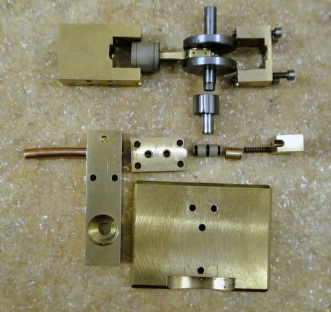
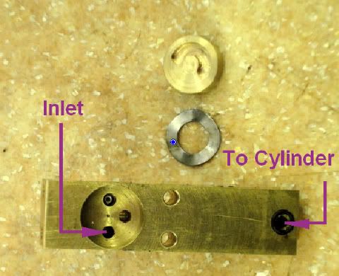
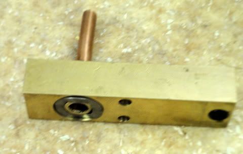
This is how it works.

(Photobucket is playing up, had to use imageshack .)


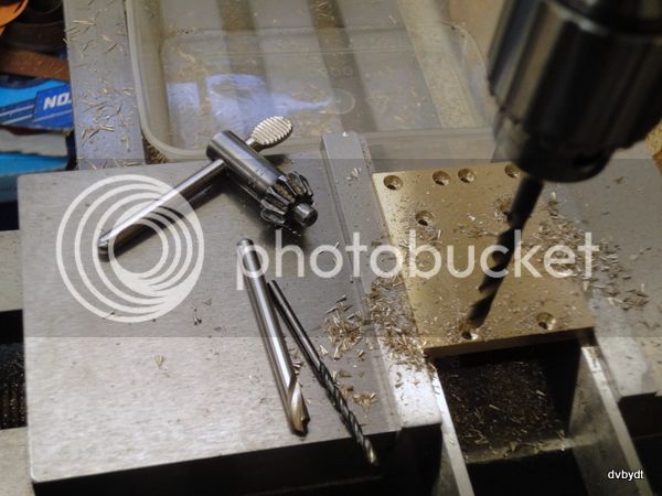
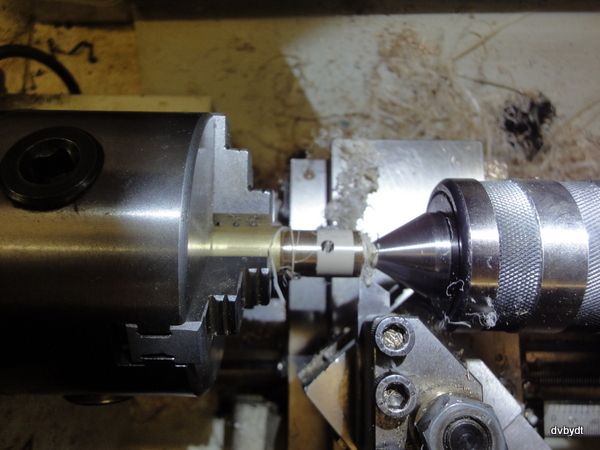
This is the set up for measuring the RPM.


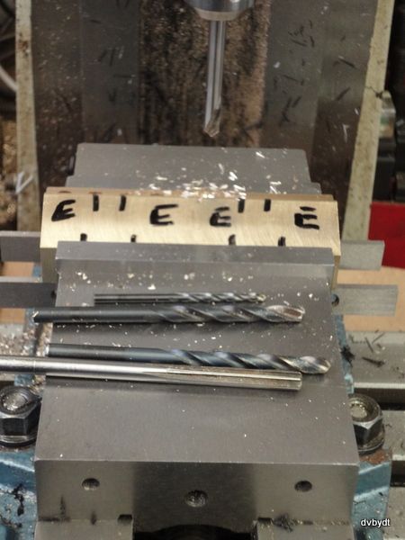
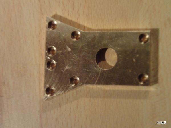
These are the results of gradually making the cam duration smaller but keeping it opening at TDC.


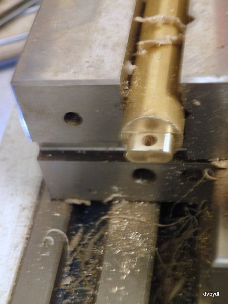
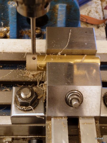
Having got to a 70 Degree cam


It looks smaller than 70 degrees but the pusher lifts the ball and admits air long before the full stroke of the cam. The cam has a hex (Allen key made) broached hole to connect to the hex on the end of the crankshaft and I was able to retard the air admission by 60 degrees for the final test.

So what did I learn from all this, bearing in mind that this is an odd type of single cylinder set up?

1. Cut-off works on air as well as steam and, in this engine configuration, can give higher RPM.

2. Torque goes down as cut-off increases - I did not have any way to measure this but in between altering the air pressure I stopped the fly wheel by hand, well, fingers, so got an impression of the torque.

3. Retarding the air admission in the last test reduced top speed but seemed to increase torque over the top dead centre air admission, presumably because the air pressure was acting at a better mechanical advantage on the piston. In this, the last of my tests, air consumption was much reduced, judged by how often the air compressor kicked in.

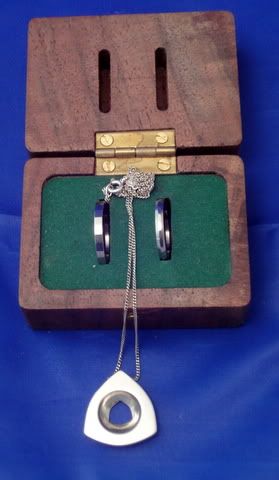
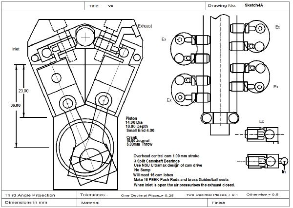
Conclusions - I will be able to run the V8 at 70 degree cut-off and retarded air entry for more economic use of air and that this little engine deserves to be made into a proper project of it's own with full drawings and a bit of bling!

Final cam timing will need more experiments on the V8 engine with only one piston installed, but I now have a few guidelines from the above.

Ian
 
It's been a while but I have found time to finish this engine.

Here are the YouTube links :-

[ame]https://www.youtube.com/watch?v=yXgaZM_b9iE[/ame]

[ame]https://www.youtube.com/watch?v=8ysh0kwC6mw[/ame]

Getting the cam right was a problem:wall:
The followers are 6mm PEEK and they are what you can hear clattering in the background. The camshaft video was taken using the 100 frames per second on my TZ40 camera.

Engine will run from about 150 up to 1600 rpm and because of the 8 pulses per rev, it is quite smooth and does not walk across the table whilst running.

Ian
 
I decided to make a Simple Single using the techniques I had learned on the V8. The crankshaft, piston and conrod are all similar and the inlet valve and pushrod are a modification of the experimental single.

Here is the engine on YouTube.

[ame]https://www.youtube.com/watch?v=9RZL3ZBo6D4[/ame]


Ian
 
Back
Top