Compressed Air V8

Home Model Engine Machinist Forum

Help Support Home Model Engine Machinist Forum:

This site may earn a commission from merchant affiliate links, including eBay, Amazon, and others.

dvbydt

Well-Known Member
Joined
Oct 27, 2010
Messages
114
Reaction score
4
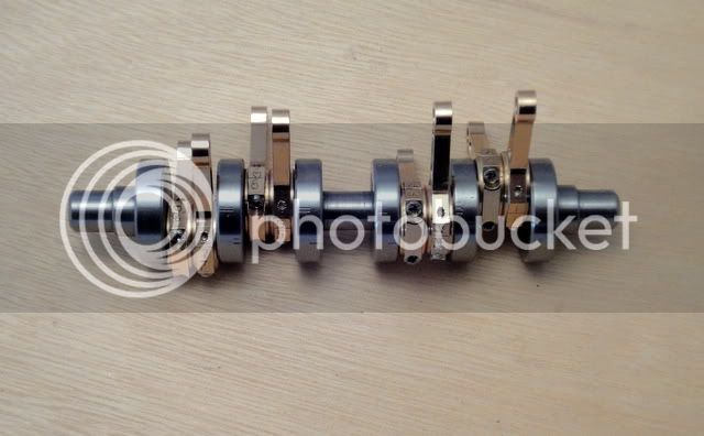
This engine was started a while ago and I just had to experiment with the crankshaft as it seemed that everyone said they were difficult. I posted my attempt here :-

http://www.homemodelenginemachinist.com/index.php?topic=11472.0

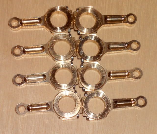
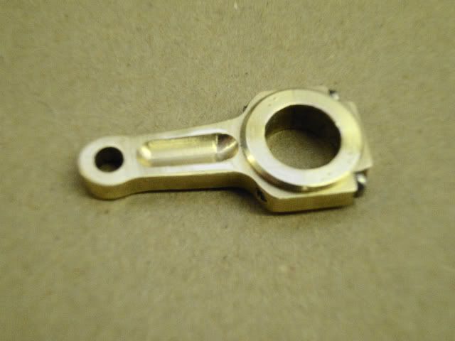
It turned out so well that it was good enough for this compressed air V8. The air porting was to be in and out like my Scrap Bin Motor (Thanks for all the interest) but Chuck Fellows showed how he had made his porting with a ball and spring. This is so elegantly simple that I had to copy this idea for the V8, so that meant I had to rethink my ideas. The Twin D/A Oscillator took up some of my spare time so the V8 has been on hold.

However I am back to it now. It will be 12mm bore 12mm stroke with the "camshaft" in the middle of the V driven at the same speed as the crankshaft by nylon gears at the front. On an air engine of this size, three bearings should be enough, ball races front and rear and a split plain bearing in the middle. The experimental pistons will be made from PEEK which is a high temperature plastic which turns easily is harder than nylon and does not have the same water absorption problems. It is expensive but I managed to strike lucky on Ebay.

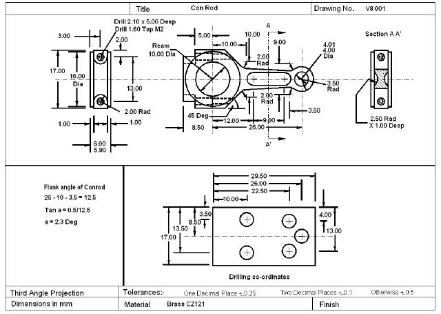
Here is the "Proof of Concept" drawing :-

V8CrossSection.jpg


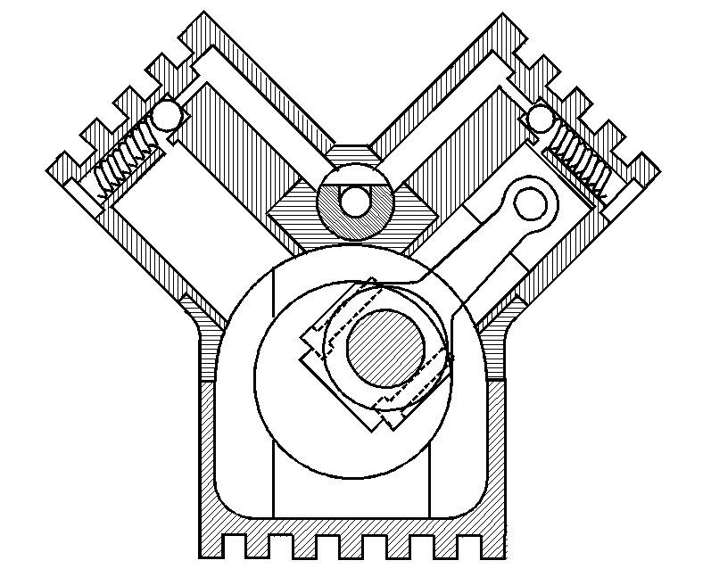
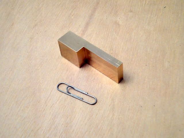
It will be made from brass bar stock. The finning is just bling. Lots of detailing to do yet, exhaust should be 4 into one both sides, so I am hoping that it will sound interesting!

Ian
 
Hey Ian, this looks like a great project. Glad to see someone trying a V8. Have you considered using a hollow tube cam like I used on the opposed 4? I think air leaks might be less of an issue...

Chuck
 
peek is good stuff I use in for the piston valves on my 5 inch gauge loco's I just make the polo mint like bits from peek the rest is Stainless. make it cheaper to replace /adjust them

they just work fine but the price for 25 mm dia is ouch


Stuart
 

Chuck,
Thanks for looking in, I will need some hand holding on this one.
Air leakage.
The top half of the crankcase will have the valve shaft running in a reamed hole.
No problems on the ends. The air connection will be on a manifold bolted to the back end of the crankcase and the front will be sealed by the face of the nylon gear with a wavy washer for tension. You might check my logic on the next bit. The engine will be running as a "two stroke", this will mean that at any "TDC" two cylinders will be "firing " together in opposite banks for 180 degrees. This means that the air supply is always flowing and the only back pressure will be from the springs pushing the steel balls into the closed position. So, hopefully there will be little air leakage along the length of the valve shaft.

Stuart,
I have built up a small hoard of PEEK from looking on Ebay there are sometimes bar ends for sale, it does not seem to attract much attention. It is harder than PTFE, a bit like acrylic and machines nicely. I will experiment with it for the pistons, using PTFE as plugs at each end of the gudgeon pin (wrist pin).

I made up a conrod, just to see if I could! The screws are stainless M2 panheads. Pictures of my method will follow when I make the rest.
Conrod1.jpg


Conrod2.jpg


Ian
 
Ian- If that con rod is any indication, this will be a very nice looking engine. A two stroke with 4 into 1 exhausts
should sound great.

Mike
 
Very nice job on that con-rod. Did you use any jigs, CNC, or ???

The air leaks, if any, are more annoying than problematic. The only issue you might have is air leaking across into adjacent cylinders. My air engines are usually made to look and sound like 4 stroke IC engines and the sound of hissing air definitely detracts from that vision. I've just never been able to get that kind of valve rod to seal very well. Probably just me.

Chuck
 
Chuck,

No jigs or CNC on this one, just made it up to see what problems there were.
I did think of using a long spool valve fitted with "O" rings to keep it air tight, but decided that it was better to keep it simple!

Thanks all for your interest, you may need patience as this one, it may take some time.

Ian
 
Ian

What a great design, I've got a design bouncing arround in my head for a V4 that was stimulated from Chucks great designs, you section drawing as helped get a few issues clear in my mind, its going to be a good few months before I start to cut metal, so I'll be following your progress with great interest.

Stew
 
Need a bit of advice.

The simple valve shaft would only have four cutouts for feeding air into adjacent, oposite cylinders, giving me a firing order of 12567834 giving equally spaced pulses into the exhaust pipe. If I went to eight ports on the shaft, I could get the usual 18436572 for a full size V8. As I understand it the reason for the "burble" on a full size V8 is that this firing order give exhaust puffs that are 1357 and 8462 into the pipe, but in the gap between 1 and 3 firing, 8 and 4 fire, in the gap between 3 and 5, 6 fires but the is no gap between 5 and 7. My brain hurts :-[

So is anyone able to advise me whether small model V8s "burble"?

Ian
 
Answering my own question, yes they do "burble". On this very impressive site he has a video of his supercharged V8 running.

http://www.weberprecision.com/

But I think for my simple engine I will stick with even pulses on the exhaust, may sound like ripping cloth rather than a f***ing frog!

Ian
 
I'm getting a bit of time to play with this engine. The trial conrod above was made from brass but I decided it would be better to use leaded bronze for the the real thing. So I cut off some disks and after a lot of milling and fly cutting, I now have these blanks :-

ConrodBlanks.jpg


CapBlanks.jpg


This is my drawing :-

ConrodDrawing.jpg


And since I want them to be all the same ;D this is the drilling fixture :-

Fixture.jpg


So, hopefully, the next post should be photos of the blanks being machined.

Ian
 
Next job is to drill four holes in each blank using the fixture. Just used my 4mm spotting drill. The

fixture is 0.25mm thinner than the blank and is clamped in the vice, then the blank is held in

position by tightening the vice.

http://i757.photobucket.com/albums/xx213/dvbydt/Air%20Motor/Compressed%20Air%20V8

/Drilling.jpg

Then drill and ream the small end.

http://i757.photobucket.com/albums/xx213/dvbydt/Air%20Motor/Compressed%20Air%20V8

/Reaming.jpg

All done!

http://i757.photobucket.com/albums/xx213/dvbydt/Air%20Motor/Compressed%20Air%20V8

/40Holes.jpg

Now for the M2 tapped holes using the same fixture vertically this time. This is the edge finder I

am using for these set-ups.

http://i757.photobucket.com/albums/xx213/dvbydt/Air%20Motor/Compressed%20Air%20V8

/EdgeFinding.jpg

Drilled the hole and hand tightened the tap in the chuck and tapped under power. I only need to
get a few threads down so that the thread is straight in the hole, it will be hand tapped through

later.

Tapping.jpg


Ian
 
Fixture in use again to drill the caps.

DrillingCap.jpg


Then the caps were milled for the screw heads.

MillingCap.jpg


Used this to make a wedge for the flank angle.

Wedge.jpg


All done.

FlanksDone.jpg


Ian
 
Milling 45 Degree on the big end, if thats what it's called on this size of conrod!

45Degrees.jpg


Finish tapping the M2 threads. Do you like my tap wrench?

HandTapping.jpg


Removed the excess from the little end. I have been using this diamond lap for deburring, it is much kinder on the edges than a fine file. As an aside it also good for plastics.

Deburred.jpg


Ian
 
Fantastic work, I can't wait to see how this goes!

Yes, I do like your tap wrench. :)
 
Jeremy, this a photo of my 3 small tap wrenches for M2, 3 and 4 and an extension. The idea is that it restricts the torque I can apply. If they are difficult it is because the tap is blunt or it is not perpendicular to the job.

Wrenches.jpg


Back to the conrods. My rotary table was used to round the small ends. The head of the M4 screw was turned concentic with the screw and used to centre the rotary table.

Truing.jpg


Then the radius was milled.

Radius.jpg


The caps were screwed on.

WithCaps.jpg


And the 10mm hole spot drilled, drilled and reamed using the fixture upside down this time.

Reaming-1.jpg


Next I made a 10mm mandril for the lathe and the sides of the conrods were turned.

Turning.jpg


To be continued............. ;)

Ian

 
After turning both sides the flutes need to be milled.

MillingFlute.jpg


Next job is numbering, then deburring and polishing.

numbered2.jpg


Another view.

Eight2.jpg


And mounted on the crankshaft.

Mounted.jpg


I've still got to decide where to drill the oil holes, but that can wait.
Well, that's the first milestone reached. The order for the rest of the engine is:-

Crankcase and valve gear.
Sump.
Cylinder blocks.
Exhausts.

All these still have to have detail drawings done, so a bit of work to get through before I start machining again.

It may be a while before I get back to it, a friend has a 5 1/2 ins gauge electric garden railway and wants me to replace the 12 bogie bearings on the engine. Should proove interesting.

Ian
 
Looks really nice. The con rods and crankshaft are very impressive.

Chuck
 

Very nice work!

That last pic looks like a piece of jewelery.


Latest posts

Back
Top