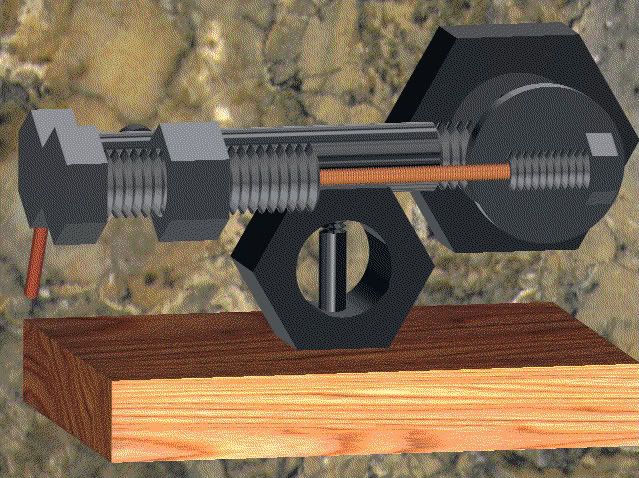
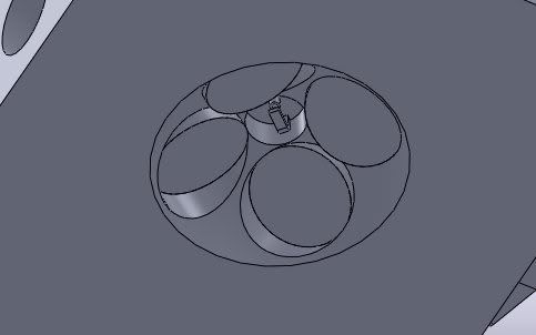
And this is typical of what I do at my real job!!! This is an industrial centrifuge, about 400 individual parts---72 engineering drawings---3 weeks work.
And this is typical of what I do at my real job!!! This is an industrial centrifuge, about 400 individual parts---72 engineering drawings---3 weeks work.
Careful, you could put somebody's eye out with that thing!
I find CAD to be very restful. Sometimes when it's gotten too late at night and I'm too tired to go down to shop, I go look for something to draw.
But, it's interesting how hard it is to get information on some very basic things.
For example, I wanted to draw up a D1-4 cam lock for a lathe. I have models of most common tapers and collets, but hadn't played with the D1-4. There are lots of drawings on the web to show the nose and the hole spacing and diameter, but I couldn't find a single thing about the cams or the studs that the cam engages. How long are the studs? Where is the cam recess on the thread? What is the radius of the recess? etc.
Bob,
The camlock pins are over complicated.
There are two cut away radii on the sides and the main radius for the lock and both have different centres making setting out a lot harder.
If you mill two flats on the sides equal to the size of the side radii you only need the one lock radius.
I made a couple of sets like that and they work fine and when fitting you can't tell the difference between these and bought ones.
This is my latest doodle, It's a 21.52 CCGT insert with 15 degrees of back rake. I thought it would be really east to make at first, but it took some doing to get the radiuses right.
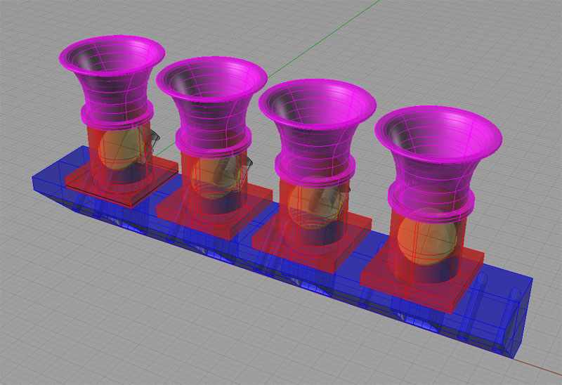
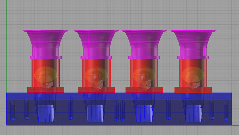
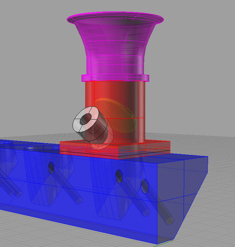
A throttle body electronic fuel injection system for a Ford 351 Cleveland (a built several Clevelands for Panteras and want to put one in a hot rod some day):
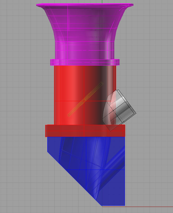
There are a lot of odd shapes involved in this one. In particular, the ports from the throttle body are round, but they have to be rectangular by the time they hit the heads on the motor. That took some head scratching. This drawing was one of the ones I did that caused me to give up on Alibre and stick to Rhino 3D. Not really so much a fault of Alibre's, as Rhino 3D's specialty is flowing curves. It's used to design boat hulls, for example.
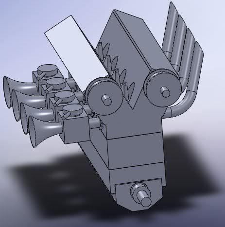
I'd love to make this engine someday, but it has a HELL of a lot of parts... although, now that I think about it, none are particularly difficult to machine, and all would fit on the machinery I have... NO! Too many projects already.