Buyng and fitting a dro to sieg sx2 mill

Home Model Engine Machinist Forum

Help Support Home Model Engine Machinist Forum:

This site may earn a commission from merchant affiliate links, including eBay, Amazon, and others.
Well it all arrived safely.Silly me,ordered it from a Melbourne supplier,expecting it to come from Melbourne.Wrong it came direct from China
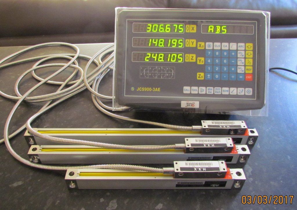
Arrived safely in 7 working days as promised,so no complaints
Unpacked and checked everything.Removed the read head transport screws and plugged everything in.Main power plug was not suitable but I had a spare
computer power lead which is OK.Checked all the axis and everything works ok
Max travels shown in photo and correspond with what I ordered.That will be all for now,i need to get some alum flat for the X axis where I will make a start
Unfortunately it 40oc outside and at least 60oc in my shed so too hot to work
The excerlent ? manual states thet the box is ABS plastic and will not tolerate high temps.May have to remove next summer.Any thoughts on high temp
detriment to the working unit ?
 
Basmak, I am sure if the DRO's on my mill and lathe are all still functional with the heat we up here that your scales will survive even if you don't.... You will love it once you get it going...
 
None of the three Dro's in my workshop have had any problems with the heat even the 47 deg C we had here in western Sydney recently and in my fibro shed it would have been pushing 50 C + easily although i wasn't in there at the time to measure it as i was busy inspecting the beers in the fridge !
 
Thanks you guys,its reassuring but will have to keep it in mind
Just going out there now for a couple of hours as it cooled down last night
 
Weather cooled down slightly so spent a few hours fitting the X axis
Mill drilled and tapped,brackets made and fitted with minor mods and
tramming to do later when I have all 3 axis to this stage.Must say it
was easier than I thought.I only had to drill and tap 4 holes to the table
without having to to disassemble the slides.Hope the oth ers go just as easy
 
Good work! I think now from memory, I trimmed the top edge of the covers using my bandsaw using its table and a improvised fence and mounted the covers straight to the holes in the scale at each end. It has been perfect.
 
Thanks Rod,the cover has a top vertical flange that would have to be cut off
The main problem is the large rad fold down the length which if fitted will
lose me another 10mm of travel.I don't mthink it would offer any additional
protection to what I already have
 
Thanks Rod,the cover has a top vertical flange that would have to be cut off
The main problem is the large rad fold down the length which if fitted will
lose me another 10mm of travel.I don't mthink it would offer any additional
protection to what I already have

Maybe roll your own guard from some 1.6mm thick Aluminium angle. You still might need to rip the top side down so it sits snug against the mill table. I nearly left mine naked until I came up with this idea and I figured some protection was better than none!
 
Hmm, when I look at what I did, I think I used aluminium angle anyway

DSC_3152_zps2e581c1e.jpg


Even if you have to buy a full length it will be under $20 and will be useful for other projects.....
 
If ever you need to strip down one of these scales, you would soon realise that the scale and head themselves requires no shielding as such, they are assembled with plenty of silicone sealant to keep thing out.

The one area that does need protecting is the underside of the main scale, that is open to atmosphere when the read head runs along the wiper blades that are fitted to the bottom of the main scale.

If you could make a small drip ledge, it only needs to be the same length of the read head, to keep that mobile opening above it away from any liquid or swarf entry.

How do I know these things?

I have shortened a glass scale so it would fit correctly on my topslide, and the vertically mounted read head was opened up to change the cable entry from the top to the bottom so that liquid wouldn't penetrate the end seal by running down the cable. They both got the correct sealant on reassembly.


John
 
Thanks John,i don't use coolant and the readhead is to the underside and
covered by the support brkt so its as well protected as it can be.
I drilled and tapped the machine and made and fitted the support brkts
Lot more work on this axis but what I have done is nice and compact
and works well.Still have to tram it all.Had to build up the machine base casting
and grind/reduce one of the feet to clear the read head lead.
QUESTION I assume the plastic read head spacers are used to set everything
and then removed for operating. Next the Z axis.Had to slow down this week
wife had a fall and is in hospital with a fractured pelvis
 
Another 2 hrs and the Z axis is finished.That was the easiest of the 3
Slide mounted direct to column and read head bracket and spacer block
fitted to head.Fits very well and compact.I would recommend the slim line scales to anyone.Next is disassemble.clean up a few things refit and tram
to check all the travels.Then its the digital readout box.Will probably fit to shed wall on the LH side and run the cables
 
Looks good. My only comment is that 3 screws is always much easier to level than 4 so maybe remove 1 screw if you can't level it.

Final squaring requires you to run the full length of the scale with a dial indicator on 2 surfaces of each scale but I guess thats what you mean by tramming.
 
Hi Rod , it is just as easy with 4 screws.You only use 2 to level in each dim
a total of 3 altogether.The 4th then is is just nipped up before the final tightening.With only 3 screws there is a possibility of deflection.
I only need the levelling screws for Y axis.The X axis is fixed to the machined table and will only need tramming on the top edge.The Z axis is bolted to the column on packs for clearance to the read head and may only need shimming
and tramming to the front edge.The Y axis needs more attention due to the
irregularities in the casting for mounting and will need tramming front and top carefully.Question,how accurate needs to be the tramming,i have heard 1 thou mentioned and the chinese book I think states 0.2mm or 8 thou.I had in mind
that better than 5 thou would be adequate unless you tell me different
Also do the plastic read head spacers need removing for use after final setup
Regards barry
 
Baz,

I always used the plastic transit inserts to hold the head to the scale for initial setups, just gently slackening the holding screws to allow it to just about slide but still keep them in sync, but on final assembly and movement they are removed.
Keep them safe though, as if you have to send one of the heads back for repair, they will stop any further damage.

John
 
Thanks John that is what I thought.Well 3 hrs in the shed before its gets too hot and all finished.Disasemmbled,cleaned up etc and refitted .All trammed up
top and side to within 5 thou.Which I assume will be adequate.Boy do I hate tramming,can never seem get the magnetic stand and dial where you want it.
The X and Z were easy but the Y was a real pain.All run easy for the full travel
and max tavel is within 5mm of that expected.Now to mount the read module
tidy up the cables,(don't know why they supply 3m) Then to refit the pleated
covers how and where I can.QUESTION the readout is towards the negative
how do I reverse to positive.Not that its important.All other functions look very technical according to the literature don't know if I will ever need anything
other than direct read.Anyone who has this system please let me know how
and what functions you find useful. Regards Barry
 
The pos/neg setting should just be a button press on the control panel, from what I remember, you have to set it to each axis individually, you might have to go through the manual to find it.

It is a couple of years since I have used mine in anger, but it depends how much you paid then how many 'gizmos' it has that you can use.

The most useful one for me was drilling a PCD., the next is drilling along an angled line and then cutting a radius. I never use the memory functions as almost all my work was done for single components and if I needed multiples of things I tended to stick them together and cut as one.

Your long leads will come in handy if ever you want convert your lathe or other machines to DRO, if the display head can be set for either Mill, Lathe or Surface Grinder, as mine can be.
If they are close enough together, you can mount the display where it can be read from both machines and just buy a couple of read heads for the lathe, just swap over the leads depending on which machine you are using.
I am sure I have seen for sale a small switch over box that saves having to disconnect anything once it is set up.

John
 
I reckon 5 thou will be fine. If the scale is at an angle, it could read less because the distance traversed is shorter. But when you do some trig, given the short length of your scales, it will be 4/5 of 5/8 of F/all... and thus be less than the accuracy limits of your mill. My scales read to microns. People say to cover up and ignore the last digit, but I seem to be able to hit a distance to +- 1 or 2 microns. There is a bit of an art to tightening the gibs to set a measurement on an axis I found.

And yes, somewhere there will be a setup routine for each axis that sets the resolution and +ve direction among other things..
 
Well its all finished now to start using it.Mounted the readout box
on the wall to the right and coiled the cables for now.Just finished reading
the instruction manual and it made my head spin.I think I will only be
using the basics.Been looking at U tube for how to reverse the travel
two ways on similar units so will give a try tomorrow when its cooler
Has anyone changed the feedscrews to ball screw without CNCing it
Just a thought,is it feasible and/or worthwhile
 

Latest posts

Back
Top