Building small carburetor with throttle

Home Model Engine Machinist Forum

Help Support Home Model Engine Machinist Forum:

This site may earn a commission from merchant affiliate links, including eBay, Amazon, and others.

Brian Rupnow

Design Engineer
Project of the Month Winner
Joined
May 23, 2008
Messages
14,978
Reaction score
8,269
Location
Barrie, Ontario, Canada
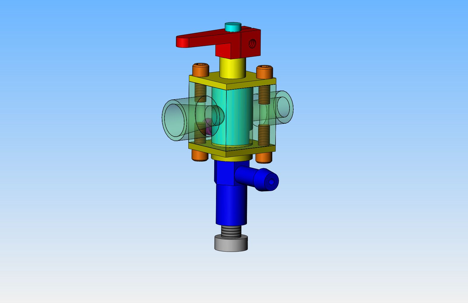
This post is not an original design by me, but rather an "imperialized" copy of a design originated by Malcolm Stride, which was originally designed in metric. I built one of these carburetors during the past year, and was impressed by how well it works. I am building a second one to try on my side valve engine. I really didn't do a lot of "rounding off" in the conversion from metric to Imperial, but suffice it to say that the inside dimension of the throat is .195" (4.95 mm), the thread on the outside of the carburetor body is 5/16"-18, and the throttle barrel is .394"---a direct rounding off of 10 mm. The tapered bore in the throat was put in there with my very recently made tapered D bit, and has a 16 degree included angle. This carburetor seems to be excellent on single cylinder engines in the 3/4" to 1" cylinder bore range.
 
Last edited:
On any carburetor with a square or rectangular body, the choice is always--Do I start with square stock and hold it in the four jaw chuck to turn round ends on it, or do I start with round stock and turn it first, then mill the square/rectangular sides. I had some 1" diameter aluminum round stock, and I am really more comfortable with the 3 jaw chuck, so my first step was to turn the diameter down to 0.835" (which is the distance across the corners of the square body), then turn the end which will receive the tapered bore down to .394". I left everything attached to the bit of 1" diameter parent stock so I would have something to hold onto with the chuck, and roughed out the diameter on the other end but left it well oversize. With this type of carburetor, it is best to drill the through hole with the throttle barrel in place, which ensures that the holes will line up properly on final assembly. Of course, I don't have the throttle barrel machined yet, so I drilled through to what would be the approximate center of the throttle barrel at .195" (4.95 mm), but left the other half of the carburetor undrilled. The hole I created allowed me to ream the tapered hole with my newly created D bit in the tailstock chuck. I then transferred the part over to the chuck on my rotary table and milled away the sides which left the square body. I then drilled and reamed the .394" diameter hole through for the throttle barrel, and drilled and tapped the holes for the bolts which hold the top and bottom plates in place, and also drilled and tapped the throttle stop screw hole, the air bleed screw hole, and drilled the air bleed hole. The attached picture shows the result up to this point, with the "part in progress" held in the chuck on my rotary table, which is mounted on the bed of my milling machine.
 
Last edited:
Of course, as often happens, I got ahead of myself, and after squaring up the carb body, I realized that I should have arranged to machine the square top and bottom covers in the same set-up, but it was too late. Thankfully, the piece of parent stock was long enough to flip "end for end", put it back into the lathe, and turn the diameters which appear on the top and bottom covers. I took two pictures of this operation, and both of them tuned out blurry---and of course I don't know that until I download my camera to the computer after I have moved on and went to the next step. --A hint--the portions with layout dye on them are the large diameters that will get squared off in the milling machine.
 
At any rate--Here we are, back in the rotary table, with the round portions squared off. Now it was simply a matter of moving things back to the lathe, drilling, reaming, threading, and parting off----
 
And "Hey Presto"--Here we have 3 almost finished parts. No finish sanding has been done at this point, the clearance holes for my #4-40 capscrews are not yet drilled in the top and bottom covers, and the hole through the air horn of the carburetor is still only drilled through to the center. You will see that I did turn the other end of the carburetor down to .312 so I could thread it 5/16"-18, and parted it off from the parent stock.
 
Last edited:
Good news--the holes I drilled through the carburetor end caps seem to have ended up in the right place. Everything goes together!!! the first picture shows the end cap which the throttle barrel extends through to attach to the throttle handle. Two of the screws on opposing corners hold the end-cap to the main body. The third bolt you see there is the air bleed control screw. Normally I would say this view shows the top of the carburetor, but there is a catch---it isn't really the top. I will explain as we get farther into this build.
 
This view of the opposite end cap shows a number of things. The rusty #10-32 capscrew is threaded into the hole which the "spray bar assembly" threads into. The single #4-40 capscrew thru the blank side of the carb body is the throttle stop screw which adjusts the idle speed of the engine. The small plain hole in the same side is the air bleed hole. The threaded end of the carburetor body has been countersunk in preperation for drilling the hole which will go all the way through to the center hasn't been drilled yet.
 
I will tackle the throttle barrel next. Lots of things going on here. The large (.394") diameter fits into the 0.394" diameter reamed hole through the carburetor body. The smaller diameter fits thru the 5/32" diameter reamed hole in the carb end cap for the throttle handle to attach to. The notch in the bottom is where the throttle stop screw bears against to keep the throttle cracked to whatever idle RPM you want the engine to have. The length of the major diameter has to be a "good" fit between the inside of the two bolt on caps.--Snug, but still loose enough to rotate. The 0.195" (4.95 mm)" hole thru the center is drilled after the throttle barrel is installed in the carburetor with both end caps bolted in place. This is the point at which I will finish the hole through the air horn (main body) of the carburetor at the same time all in one set up. The small hole in the bottom of the throttle barrel is where the nose of the "spray bar assembly" pokes up through, and it is a clearance hole, because although the throttle barrel rotates to control the speed of the engine, the nose of the spray bar assembly doesn't. That is kind of a hard concept to get your head around, but it works very well, and does make sense after you have though about it for a while.
 
Last edited:
So--here is the tricky part I alluded to earlier, when I said that what would normally be the top of this carburetor wasn't really the top. On all of my engines, I set the gas tank up so that the top of the gas tank is about 1/4" below the center of the carburetor to prevent gravity flooding and/or draining the tank. However, due to the way the needle valve on this carburetor screws in from what would normally be the bottom, the fuel will leak down past the 10-40 threads on the needle valve and drain the gas tank when the engine is left unattended. I solved that problem by turning the carburetor 90 degrees so that the centerline of the needle valve sets in line with the center of the main carburetor air passage. That solves the leaking problem, and the carburetor doesn't care. It will work well in any rotational aspect.

 
Last edited:
My apologies--The hole through the center of the carburetor is .195" (4.95 mm). I had to go back and edit my previous posts where I said the hole was 5/32" diameter. I didn't realize until I made the throttle barrel about an hour ago that I had posted the wrong size. I actually did drill a 5/32" hole thru the throttle barrel and the other side of the carburetor body, and then I couldn't figure out why there was a step at the bottom of the taper on the intake side where the throttle barrel started. I had another look at the drawings and seen that the hole was actually dimensioned as .195". (4.95 mm). My bad--I redrilled the hole to what the drawings said and all is well now.----Brian
 
This is what a view "down the hole" looks like from the intake side, with the throttle barrel in place and drilled out to finished size. I'm pleased. There is no "step" evident, just a nice smooth taper almost up to the throttle barrel, then a plain round hole with parallel sides all the way out thru the rear (threaded side) of the carburetor. There isn't a lot of "meat" left between the root of the 5/16" external thread and the 0.195" diameter thru hole, only about .035" wall thickness at the root of the thread.---However, this is enough, although I wouldn't want to crank very much torque on that carburetor body when assembling it to the intake manifold. A view from the rear side shows that the hole ended up nicely concentric to the outside threaded diameter---Something I always hope for, but don't always achieve.

 
Of course, every carburetor with a throttle needs a throttle handle----How else could you get your engine make those really neat VROOM, VROOM noises. I know that the head of that air bleed screw looks awfully close to the underside of the handle, but it does clear.
 
Last edited:
Moving on to the spray bar and needle valve, I am going to try something I first seen suggested by Chuck Fellows. Although I CAN drill holes smaller in diameter than 1/16" in my lathe, I am not terribly comfortable with doing so, and I often wonder what degree of concentricity I really am achieving. The local hobby shop sells rigid brass tubing which measures .062" on the outside diameter, and as far as I am able to measure, .031" inside diameter. The sewing needle in the picture measures .035" in diameter, and will fit into the end of the brass pipe about 1/4" before the diameter conflict won't let the needle go in any farther. Instead of attempting to drill a .031" hole thru the nose of the spray bar, I will drill a 1/16" diameter hole and solder a short section of this brass tube into it, and solder the needle into a threaded section with a knurled o.d. to become my needle valve.
 
Hi Brian, I recognise the carburettor as the same that I built for the Nemett Lynx, it does work well. When I was making mine I also thought of using some tube, I had some 15gauge (1.8mm) dialysis needles that I thought might work, but ended up just drilling my own hole in the spraybar.

Paul.
 
I must admit, I don't have a warm, fuzzy feeling about this upcoming silver soldering job. it sounded like a good idea, but how that I see the size of what I have to do, Oh Boy!!! Ah well, nothing ventured, nothing gained---Wish me luck!!!
 
This shows a method I have used (with varying success) over the years to keep silver solder out of areas I don't want it to go. The secret seems to be in letting it dry really good before putting a torch on it. I have learned however, not to use it on knurled knobs. The Wite-Out keeps the silver solder away, but seems to flame harden into something almost ceramic like that is damned near impossible to get out of the knurling. --It can be removed easily from an external thread by running a die over it to clean it up.
 
It seems that the soldering Gods have smiled on me.--Either that or I'm getting better. I put the smallest tip I have on my oxy acetylene rig, held my breath, and actually got the silver solder where I wanted it and no where else. I did have to set the part back up in the lathe and cut away the "cone" of silver solder that formed around the 1/16" diameter pipe a little bit, but all is well. The dance isn't over yet though. I still have to solder the fuel inlet pipe to the side of the "spray bar". First though, I have to set it up in the rotary table and mill the large diameter into a hexagon.
 
looks good brian.
i'd like to try one on my J Howell Vtwin.
can i purchase dwgs?
jim niessink
 
Sometimes ya just need that third hand. I bought this little gizmo at a yard sale for $2 but I see that they are still sold brand new. They really work great for soldering wires together when you need one hand for the soldering gun and one for the solder----and it's great for carburetor work. There is a 1/16" diameter hole thru the center of that fuel inlet held in the third hand, but I don't drill it completely through until all the soldering is done. If you drill it all the way through before soldering, it has a tendency to get filled with solder. After the soldering is finished I set it back up in the mill and drill it through until it breaks thru to the center of the carburetor. I'm getting very close now---All thats left to do is final assembly, determine what length the needle has to be cut to, and solder the back end of the needle to the head of the brass knurled needle valve adjuster

 
By the way---What's a good way to get that red crap off of brass after silver soldering? I have tried scrubbing with an old toothbrush and plain water, scrubbing with an old toothbrush and silver polish, soaking the part in a 50/50 mixture of white vinegar and hydrogen peroxide, all to no avail. Short of sanding it off, I can never get rid of it.----Brian
 

Latest posts

Back
Top