Building small carburetor with throttle

Home Model Engine Machinist Forum

Help Support Home Model Engine Machinist Forum:

This site may earn a commission from merchant affiliate links, including eBay, Amazon, and others.
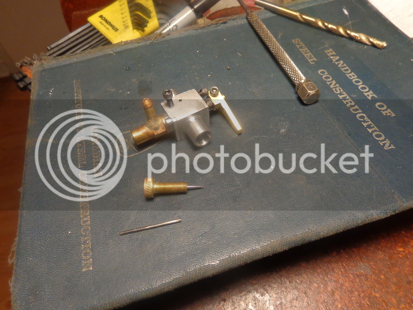
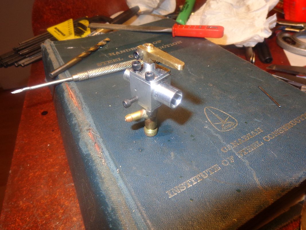
We're finished!! Okay, what can I tell you? First, how do I know how long to let the needle stick out past the tip of the brass threaded piece of the needle valve.---Well, I make sure the tip of the needle alone is seated into the hole in the inside end of that tiny 1/16" tube inside. You can tell, because it will go in about 3/16" +/- past the bottom of the hole drilled for the #10-40 threads. Then I slide the threaded brass portion down over top of the needle and screw it into the carburetor body until it absolutely won't go in any farther (finger pressure only). Then back it off two full turns. Measure how much needle sticks out past the back side of the knurled portion. That is the amount that must be cut off the rear piece of the needle. After you have cut it off (I use an abrasive wheel on my air grinder), use fine (220 to 300 grit) emery cloth to sand the last 1/4" close to where you cut it off. Those needles have some kind of clear coating on them that silver solder won't stick to. Then, making sure the needle is fully seated again, set the whole carburetor up in the vice, with the knurled brass bit unscrewed two full turns from "tight closed), and solder it. (It helps to use a countersink tool to put a small crater in the outer end of the brass knurled part for the solder to pool in around the needle). The silver solder will have a tendency to "hump up" when it flows, and you want to be able to grind it down flush on your belt sander, but enough will be left in the crater to hold the needle solidly.

 
One last view thru the bore. You can see the nose of the spray bar, sticking up thru the hole in the center of the passage. The fact that it is sticking up there in the airflow is enough to make the air speed up when it is being pulled past it, and that creates the "venturi" effect which will pull fuel up from the tank 1/2" to 1". The amount of fuel available is controlled by the needle valve, with the needle "screwed into" the other end of that 1/16" diameter tube. That is how you set the mixture to "richer" or "leaner" to best suit your engine. (This is not intended to control the speed of your engine.) The amount of air rushing thru the passage is controlled by turning the throttle barrel and impeding the air flow. That is what creates the "throttle effect" and lets your engine run faster or slower.--Of course there is a direct relationship between the two factors. The more you open the throttle, the more air will rush through the carburetor, and consequently create more "venturi" effect, thus pulling more fuel thru the spray bar. When you close the throttle, less air passes though, less venturi effect is created, and consequently less fuel is pulled from the spray bar.
 
In the picture directly above, you will see a .045" thick brass washer just above the hex shape of the soldered spray bar assembly, next to the aluminum carburetor bottom plate. Why is it there, when it doesn't appear in any of the solid models. Well, my friends, that is the "bit" that buys me some tolerance on all the pieces that screw together and have to meet fairly tight "end gap" tolerances. If the spray bar screws too far into the carburetor bottom plate, then it will press against the underside of the throttle barrel and prevent it from being turned. During final assembly, I did a bit of measuring and determined that a washer that thick would let me tighten everything "snug" and still have a freely rotating throttle barrel. Probably if I built ten more identical carburetors, that washer would end up being a different thickness on every one of them.----Brian
 
I knew when I built the carburetor that it wasn't going to just be a straight bolt-on to my side valve engine, since being mounted sideways it takes up more room than the Chuck Fellows carb that I had built for this engine originally. I didn't want to build a whole new intake manifold, so I made up a 45 degree adapter to use with the original intake manifold. The 45 degree offset gives me ample room beside the "muffler".
 
The engine runs really well with this carburetor on it. The lowest sustainable rpm is 700 rpm, and the top rpm had increased to 3000 rpm. I have played with the ignition timing a bit, and with a lot of advance the engine will rev up close to 4000 rpm (which is very scary). However, with the ignition advanced that far, it doesn't idle down particularly well. I backed the ignition timing off and the engine sets there and idles very well.
[ame]https://www.youtube.com/watch?v=zl_v7HHpArI&feature=youtu.be[/ame]
 
Last edited:
By the way---What's a good way to get that red crap off of brass after silver soldering? I have tried scrubbing with an old toothbrush and plain water, scrubbing with an old toothbrush and silver polish, soaking the part in a 50/50 mixture of white vinegar and hydrogen peroxide, all to no avail. Short of sanding it off, I can never get rid of it.----Brian

I believe it is copper that has been plated onto the brass by the acid pickle. Try a fresh acid. I believe the copper builds up as the acid is used to pickle objects. I think this same process was also used to copper plate parts so they could be scribed, like using Dykem blue, but the copper was more uniform and didn't wipe off.
 
Ron--I don't use a pickling solution. I just use a bit of flux paste on the area to be soldered. You may very well be right though. When I heat the flux paste with my torch it liquifies and runs like water---and I think the red colour is wherever the liquid flux runs to. Of course, that still doesn't solve how to get it off.
 
For cleaning up after silver soldering, pickling in dilute sulphuric acid, about battery strength, should remove or soften the flux residue. Then rinse and scrub in hot soapy water.
Charles--I just read on the internet today that heating a cup of white vinegar with a tablespoon of salt dissolved in it would produce a concoction that would get rid of the red stain left over from the solder flux. I may have to try an experiment and see.---That seems somewhat safer than using sulphuric acid.
 
I played a bit more with the needle valve setting on the new carburetor and was able to get the engine idle down to 670 rpm, but it simply won't go any slower than that.
[ame]https://www.youtube.com/watch?v=CQ0vm7rpf4U&feature=youtu.be[/ame]
 
Hi Brian
Thats pretty damm good for a single 4stroke engine
cause 670 is really335 power stroke
If you check your video closely at 1.08 and up you can see your
oring stretching on each power stroke..
Thats how we use to read RPM on the first ditributorless
engine
 
Yes Luc, that is kind of strange to see that o-ring stretch when the engine fires. You wouldn't think that the plastic fan has that much resistance to turning, however it must have enough mass/inertia that the o-ring stretches a bit on every firing stroke, then "catches up" on the exhaust stroke. ---Brian
 
Brian, did you ever make plans available for this carburetor? I think I could just about make it from the pictures and text, but in particular I am unsure about the air bleed hole size and placement.

I know this is a really old thread, and I am too new to the forum to know what the custom may be concerning reviving necrothreads - my apologies for the possible transgression!
 
Back
Top