Building a Bigger Benson Engine

Home Model Engine Machinist Forum

Help Support Home Model Engine Machinist Forum:

This site may earn a commission from merchant affiliate links, including eBay, Amazon, and others.

Jasonb

Project of the Month Winner!!!
Project of the Month Winner
Joined
Mar 30, 2008
Messages
3,818
Reaction score
1,298
Location
Surrey, UK
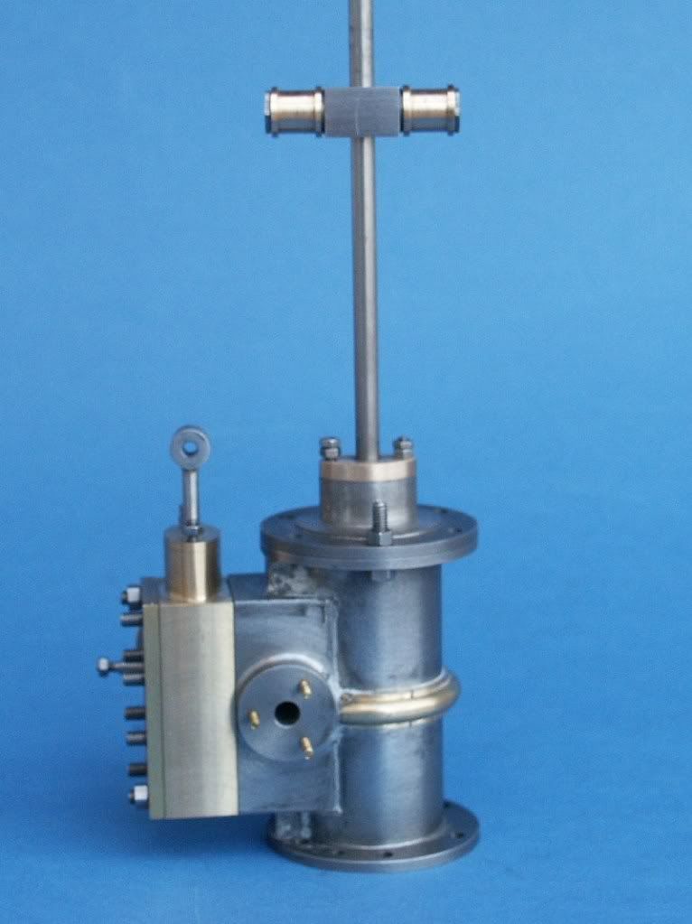
Some of you may have seen my intention to build this engine mentioned in other posts over the last couple of years, well I’ve now got round to doing some as a bit of light relief from the Fowler and IHC that I have on the go.

The engine is based on one of a range of vertical pillar engines made by W.Benson in or around 1862 and this is a contemporary engraving showing the engine. More about W.Benson can be found here

db_IntExh17.jpg


I have always liked Anthony Mount’s (AM from now on) models and this engine is shown in Vol 2 of his “Historic Engines Worth Modeling” but at 1/12th scale is a little small for my liking so I have scaled it up to 1/9th scale giving a flywheel of around 10” which is within my lathes capacity. The book is really a series of reprints of the various build series that have appeared in either ME or EIM and includes almost all the drawings. You can also buy the drawings or drawings & castings from Bruce Engineering
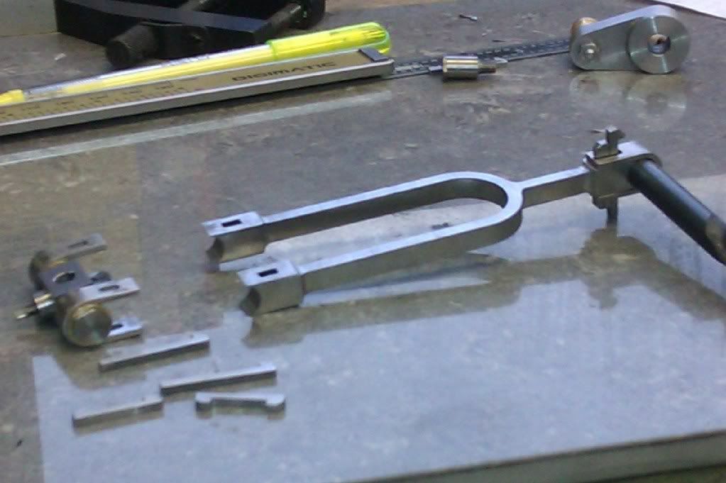
I’ve been making odd bits when I had a moment over the last couple of months but will try to describe things in the order they appear in the book. Some photos are not upto my usual standard having been snapped with the phone between machining.

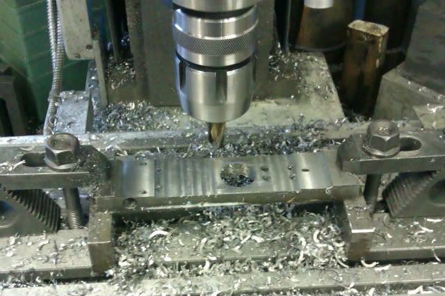
Starting with the rather organically shaped base which would come as a casting. I had been tossing around a few options for making this such as building up from 3 separate layers or carving from the solid (probably aluminium as I only intend to run on air) but the idea of getting all the curves to flow into one another was a bit off putting.

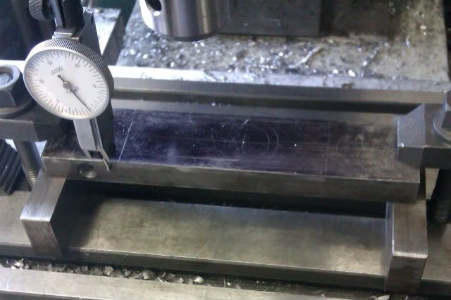
In the end I decide to use Corian as I had some left over from work and knew I could shape it with my usual woodworking tools. As with most corian jobs I started with a template of 6mm MR MDF as its easier to do any blending of curves in the soft thin MDF. The main centre holes for the cylinder, column and pump were co-ordinate drilled and then these were used to locate the curves centrally on the rotary table.

IMAG0191.jpg


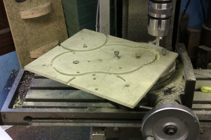
I then drilled the same 3 centres into the corian and at the same setting did all the bolt hole PCDs using the function on the DRO before rough cutting to shape on my smaller bandsaw.

IMAG0192.jpg


IMAG0193.jpg


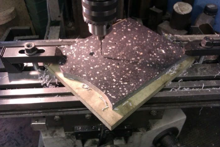
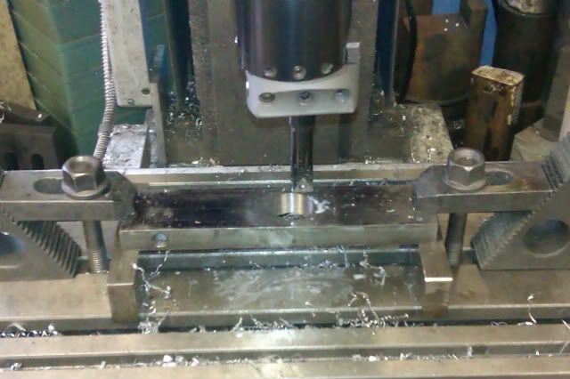
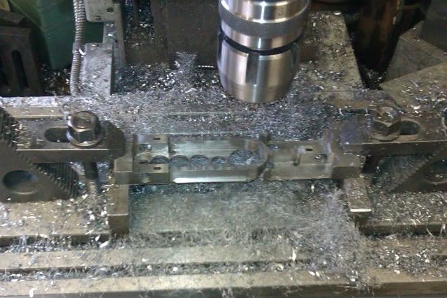
Next the router table was set up with a replaceable tip flush trimmer, the template pinned to the Corian using the centre holes and routed to the shape of the template.

IMAG0194.jpg


The trimming bit was then changed to a 1/8” rad roundover bit with small bearing to give a 1/16” quirk and the moulded edge run.

IMAG0196.jpg


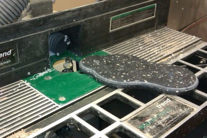
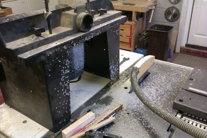
The only downside with routing Corian is that the swarf comes off like confetti and being a plastic sticks to everything due to static even when using dust extraction

IMAG0198.jpg


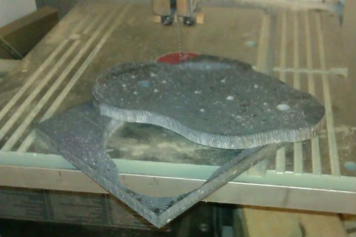
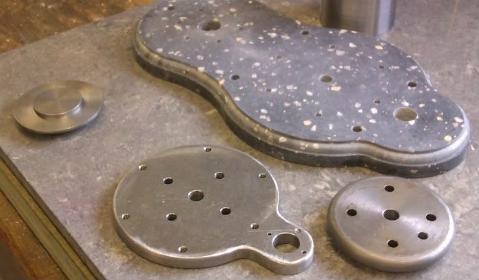
And here it is done together with from left to right the cylinder base, column base and another section from the bottom of the column.

IMAG0199.jpg


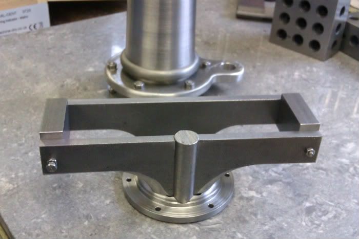
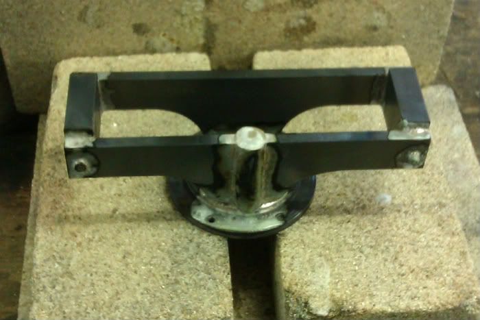
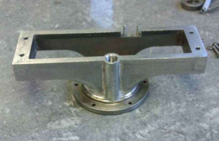
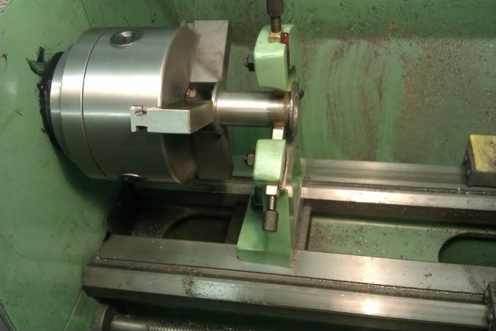
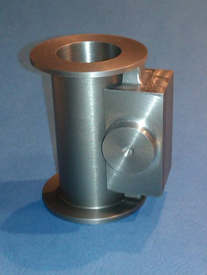
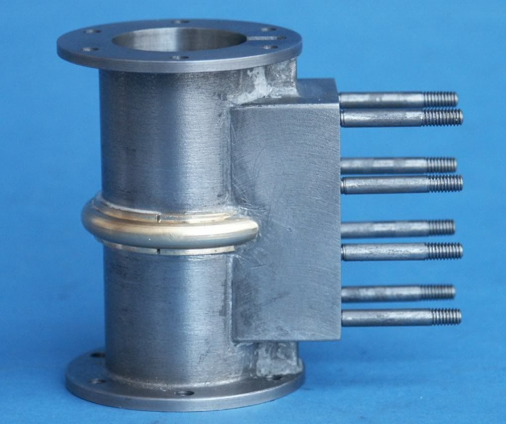
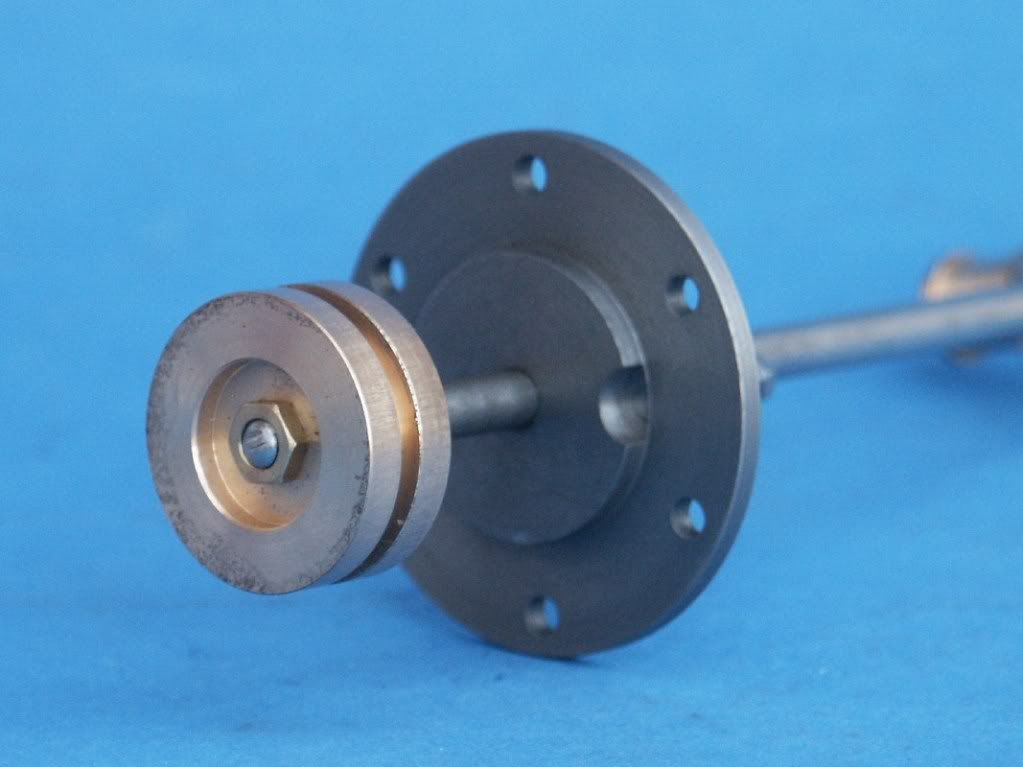
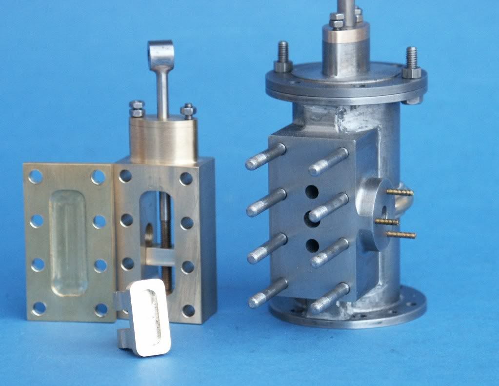
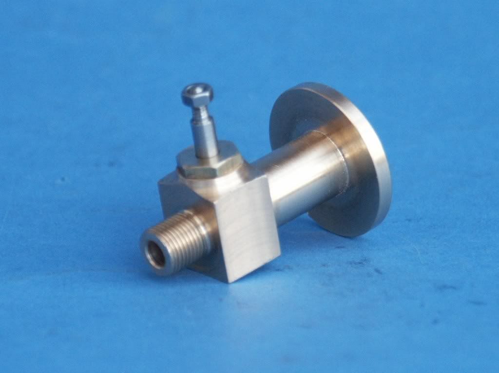
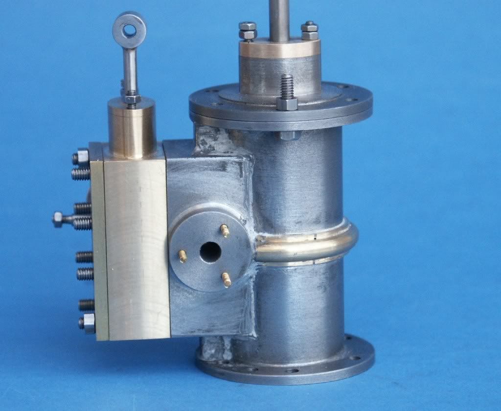
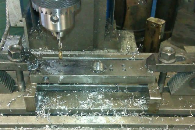
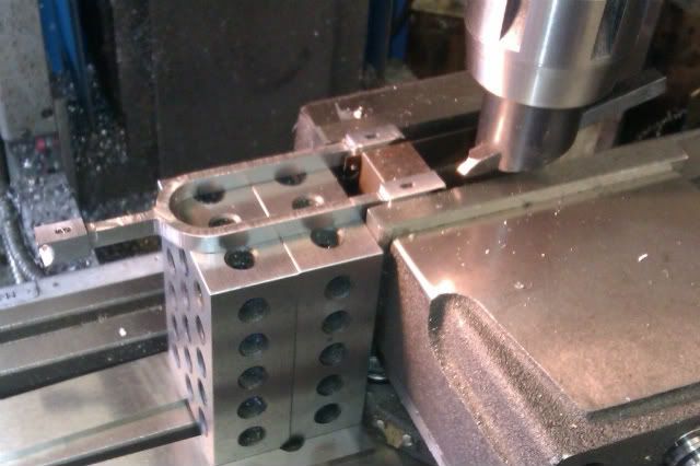
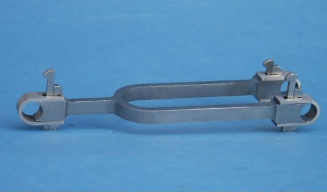
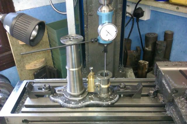
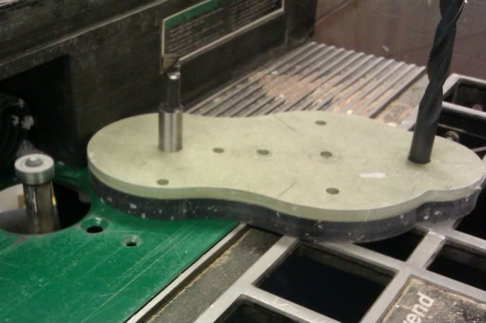
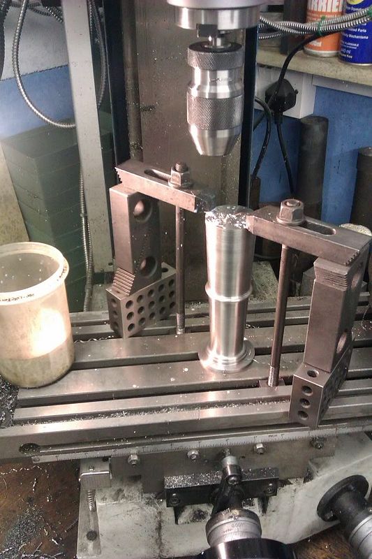
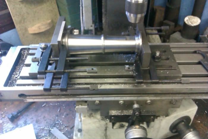
Next up is the column, AM has this drilled right through and uses a M8 stud to hold it to the base and keep the entablature in place but I opted to make it from 4 sections held together with CSK socket screws and then use the actual flange bolts to hold things together. By having the top and bottoms as separate parts the main column could come out of a 6” length of 1 .75” steel. Here it is having one end drilled & tapped for the CSK screws

IMAG0183.jpg


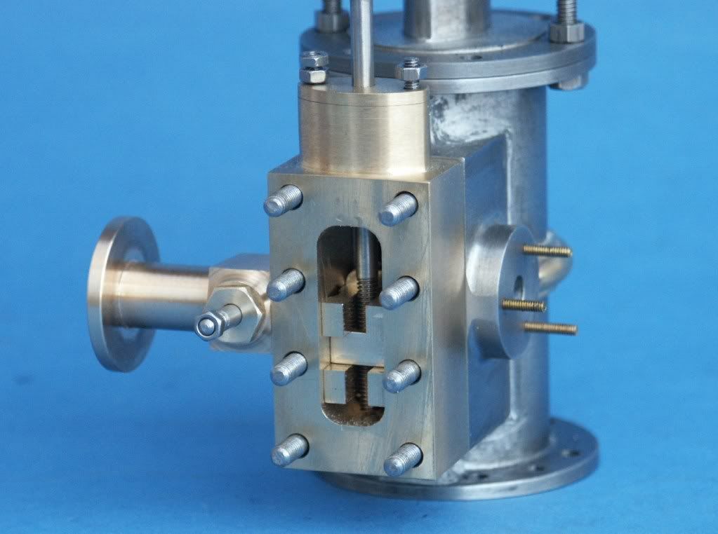
And with it all assembled the flat for the piston rod guide milled and tapped, the base was still rectangular at this stage so I could clock the whole thing true. The toolmakers clamps are just to take out any flex, there are two hold downs on the back left angle plate that take the load.

IMAG0184.jpg


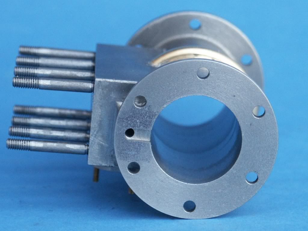
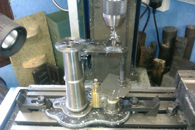
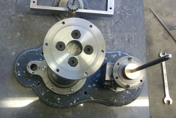
And a view from above showing the screws and how I used a spigot/hole on all parts to keep things concentric
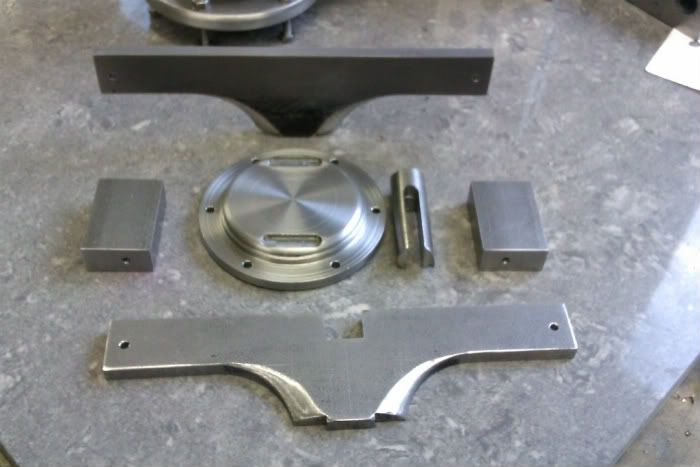
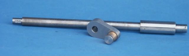
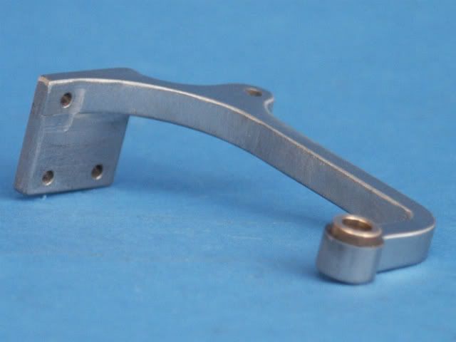
IMAG0202.jpg


Next up it’s the Entablature
Jason

 
Hi Jason, glad to see it here at last, I shall watch your build with deep interest ;)

I particularly like your use of Corian for the base and the use of a router - very 'lateral'.

Really looking forward to the coming posts as it looks as if you are a fair way in

Regards - Ramon

 
This looks like it will be a beauty!

Looking at the engraving, I can't figure out how the split-fork connecting rod doesn't interfere with the piston rod guide. Or maybe the guide has a U-shaped bend in it that you can't see from this angle?
 
I had the same thought about the piston rod yoke. There is no way for it to go from side to side with the stroke of the engine without hitting the vertical rod.
gbritnell
 
Yes the bracket curves round to support the governor rod and then back to pick up the piston rod.

J
 
Moving swiftly along we come to the entablature. This is again supplied as a casting so I had to fabricate it from steel. The first item being a simple stepped disc that bolts to the flange at the top of the column, I added a couple of slots to locate the side pieces into so they would not wander during soldering.

The four sides of the “box” were then made up from 3/8” & 3/16” steel with a screw in each corner to hold it together, the faces of the two 3/8” blocks were dot punched to raise a burr so the solder would flow into the gap.

There is a boss that the governor shaft pivots in, this was done with a bit of 7/16” rod with a groove up most of its length to create a halving joint, the other half of the joint was done by plunge cutting with a 7/16” slot drill.

All the top surface was left a little oversize so it could be milled true to the flange after soldering. Here are all the parts with a bit of hand filing to blend the sides into the flange.

IMAG0186.jpg


And test fitted together

IMAG0185.jpg


It was then taken apart, fluxed with Tenacity No5 before silver soldering

IMAG0187.jpg


After a clean up the top surface was milled back to finished size and the various holes added. The solder needed very little cleanup and just a lick of JB Weld to the base of the governor boss had it finished off.

IMAG0200.jpg


J
 
Beautiful work Jason :bow: :bow:

I am looking forward to see the engine coming together bit by bit and learn from your skills!
Really like the way you made the base, shows how you can make use of a "standard" tool just used in a different way.

Regards Jeroen
 
Way to go Jason!

This is going to be another thing of beauty...again! :bow:

I have got a set of castings for this engine from Polly. I didn't realise quite how small it is, and I have been too chicken to attempt it yet. Maybe soon.

At least I will know how by the time you have done yours...at a magnification that I can see! :big: :big: :big: :big: :big: :big:

Andy
 

The bearing brackets and crank should follow next but we will come back to them, in the meantime here is the cylinder/valve construction.

I had been intending to fabricate the cylinder from bronze and silver solder it all together but seeing Ramons recent table engine post where he assembled the parts with JB Weld thought that I would give that a go.

The main cylinder and end flanges were machined from a length of 45mm cast iron bar, here you can see the soft jaws and fixed steady being used while the cyl is turned down to finished length.

IMAG0161.jpg


The valve block was cut from a piece of 40mm CI plate and most of the work was done in the mill with the exception of the exhaust pipe flange which was done in the 4-jaw in the lathe.

IMAG0165.jpg


The decorative ring around the cylinder was done in brass and had to have a few kerf cuts on the inside to allow it to flex over the cyl OD. All was then cleaned down with cellulose thinners before being stuck with JB weld and left for 24hrs. I had left the valve face over size so it could be machined back true to the cylinder ends and the JB weld held up to the 0.025” cuts with a 40mm indexable end mill across the face. Ports and stud holes were drilled at the same setting, still needs a bit of filleting added with some more JBW but that can wait until the engine has been test run.

PICT0341.jpg


PICT0342.jpg


With that out the way the top cylinder cover, piston & rod were straight forward turning jobs, note the small notch to stop the cover spigot blocking the steam way in the cylinder flange.

PICT0340-1.jpg


Next up was the valve chest, this was machined from some 1” x 1” brass bar, unfortunately the photo of the gland being shaped was out of focus but I used a boring head with a tool set for cutting outside diameters to form the two shallow curves which were then blended at the ends with a file.

IMAG0128.jpg


IMAG0130.jpg


The valve Puck was milled from bronze, as my 1/8” milling cutters were a bit short the groove for the valve rod was cut with a 1/8” slitting saw.

IMAG0211.jpg


AM shows the valve chest cover as a plain flat sheet but I milled out a small panel for a bit of interest. With hindsight all the cylinder fixings would have been better at 6BA rather than the 5BA that the 1.5x enlargement scaled out to as they look a little heavy, I’ll use 6BA size hex nuts on teh 5BA studs so things won’t be too bad.

PICT0339.jpg


The governor works a small valve that screws into the side of the valve chest which was just machined from brass and stainless for the valve spindle. I have not finished the pipe flange yet as it has scaled up quite large so may reduce the dia a bit more and place the bolt holes to suit.

PICT0343.jpg


And finally here are a few shots of the various bits assembled.

PICT0338.jpg


PICT0337.jpg


PICT0336.jpg


Jason
 
That looks awesome Jason!

Nice fabrication job....

Dave
 
HI Jason
Top Job Buddy
Pete
 
As our American cousins might say...

Holy Shamoly!!! :bow:

You and Ramon are raising the bar above the top stops!!!! :bow:

I had better take up knitting :big: :big: :big: :big: :big:

Andy
 
I picked up a piece of 1 ½” x ½” steel at Ally Pally last week that I needed to make the con rod out of so thought I would have a got at that this weekend, the rod is a “tuning fork” shape with wedged straps at both ends to retain the bearings.

I cut off a 6” length so there would be some waste at the ends to hold the work buy then squared up an end and reduced the width to 1 1/8” and while in the vice drilled the holes for the bearings before doing the basic marking out. The bar was then clamped to the mill table on a couple of spacers and clocked true.

IMAG0234.jpg


The first operation was to set the DRO to zero on the centre line and at one end then the hole that forms the base of the two forks was drilled out to 5/8 before switching to the boring head and opening upto 0.846”.

IMAG0235.jpg


Next I drilled all the internal corners with a 3/16” stub drill and the ends of the wedge slots with a 3/32” drill.

IMAG0236.jpg


The thickness was then reduced on the top face first with a flycutter to remove the bulk followed by a ½” slot drill that had the corners reground to 3/32” rad. The two ends were left 10thou over thickness so they would remain attached to the clamping waste at the ends.

IMAG0237.jpg


I then drilled out some of the waste between the forks before hogging out most of the metal with a ½” cutter before switching to a 3/16” FC-3 disposable cutter to finalise the profile leaving a bit of metal on the bottom to help keep things rigid. The outside of the curve was done using the “arc” or “radius” function on the DRO cutting with a 10thou overlap, I had not used this function in anger before and was very pleased with the results, the curve just needing a touch of Emery to remove any tool marks.

IMAG0239.jpg


With the shape complete I flipped the work over and reduced to thickness, followed by cutting through the bush holes. It was then just a matter of setting the ends up in the vice and removing the last 10thou from each side. Note the packing between the forks to save crushing them.

IMAG0240.jpg


All that was left was a bit of file work to square up the wedge slots and a general cleanup. The wedges and cotters had been made earlier by machining the profile into the end of a bar and then slicing off with a slitting saw.

IMAG0220.jpg


And this is as far as I have got, the bottom two wedges still need final fitting and then the whole lot can be given a better cleanup. The straps were made by pressing them into a suitably cut “U” shape in the side of a bar with a piece of rod the same dia as the bearings.

IMAG0242.jpg


Jason
 
Great build Jason very informative, very interesting use of adhesives and materials.

Thanks for showing

Stew
 
Awesome work as usual Jason!!! ;D

Your posts are always full of interesting info and tips!
I also like the use of the JBWeld from Ramon's Table Engine post!!!

Very neat!!!

Andrew
 
This is going to be a joy to behold when it's done - get a move on! ;)
 
Well the cold has not kept me out of the workshop this weekend, having to file the piston rod guide to profile helped stave of hypothermia.

I've jumped ahead a bit but having got the engine to a stage where it could be test run I could not resist plugging in the compressor, here is a short video.

Its running on 10psi and I should point out that there are No gaskets, No gland packing and No piston ring material yet so should be able to get it down to a nice smooth tick over once its all set up properly and the governor is fitted.
 
Making a split cotter bearing is tough enough...making two IN LINE on the end of a flexible arm is amazing!

:bow:


Dave
 
Cracking Job

:bow: :bow: :bow:

Stew
 
Well I suppose we should get back to the actual construction.
Last time I left off with the con rod just about finished and here is a better picture taken with the camera rather than the phone

PICT0336-1.jpg


The next logical part is the crank which was a simple turning job in the 4-jaw followed by a bit of filing. The crankshaft is shown with a larger dia where the flywheel mounts, rather than machine this all out of a large dia bar I silver soldered on a sleeve and then mounted between centres to machine the OD down to size before cutting the slot for the keyway.

PICT0341-1.jpg


The bearing blocks that support the crankshaft were machined from scraps of aluminium all fairly straight forward. The shallow curve to the edges was done with a boring head swinging about a 5” radius. Bearings are not split just turned from SA660 Bearing bronze and to top it all off a little form tool was ground up to shape the outside of the oilcups and the inside opened out with a 3/16” ball nose slotdrill.

PICT0344.jpg


The construction series describes a method for making the eccentric straps that I had not used before so I gave it a go. Start with a piece of solid brass or thick wall tube, I used part of an old plumbing fixture. The tube is machined approx to OD then transferred to the mill and has shallow slots cut on opposite sides and at 90 deg to these small circular recessed are milled. You then silver solder in strips of brass for the clamping lugs and small brass bushed for the rods. Its then back to the lathe to bore out and part off the complete straps, note they are not split but on final clean up I will scribe a grove to suggest they are. The eccentrics have a narrow groove in them which engages with a spigot on the end of the eccentric rod and keeps it all together.

PICT0340.jpg


The piston rod guide is a tricky little fabrication and as some people queried at the start of this thread it has to curve around the conrod to avoid being hit and also provides a guide for the governor reach rod. I started out by silver soldering two bits of ¼” flat bar together and then drilled for the mounting holes , the whole engine was then bolted down to the mill table and a coax indicator used to pick up the cylinder bore.

IMAG0245.jpg


Next the embryo bracket was bolted to the column and the two holed drilled for the piston and governor rods, not the use of a bit of studding and two nuts to act as a jack so the bracket does not get bent downwards with the drilling pressure.

IMAG0246.jpg


With all holes positioned it was just a case of cutting and filing to profile and loctiting in a bronze bush

PICT0337-1.jpg

J
 

Latest posts

Back
Top