


C
compound driver
Guest
HI
Well here goes, this is the build on my 2 inch traction engine boiler. Give some leaway to posting times and such as I hate typing.
A word on safety;
I am writing this as a description of the way I build a copper boiler and not as a full detailed lesson on how to make steam pressure vessels. please think about the following for a few moments before you think about trying the job.
Boilers are pressure vessels and have to be of a very high mechanical standard to be safe and insurable.
In the process of the build I will use sulphuric acid both dilute and 99% it burns either way and hurts like all hell if it splashes on you.
The soldering equipment is both propane and oxy acetalyn both are dangerouse and should be treated with a lot of respect. The chances of burning a hose are real and the end result is almost always very bad be carefull with what you are doing.
The only silver solder to use is Easy flow 2 it contains cadmium and all care should be taken not to breath the fumes.
During the soldering the copper hits 650 degrees in places and 250 degrees all over be aware that its easy to get a very bad very seriouse burn from the boiler gas jets or dripping molten brass/silver.
Ok the good bit.
The plates and tube have been ready for some time in the basic formed state. Now at the start of the assembly work
the plates and tube are made ready to fit together this is essential as during the forming of the plates some roll will be put on the flanges of the boiler plates.
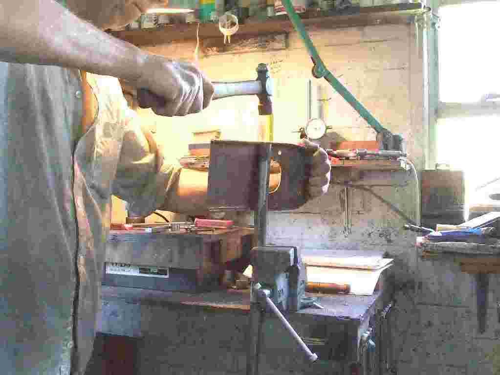
Picture shows me bashing out the over bend on a 7/8th steel bar held in the vice. Once this has been done the flanges are filed and then given a clean up with scotch bright. Keep the flanges square and as dent free as you can it uses less solder and gives a good tight joint.
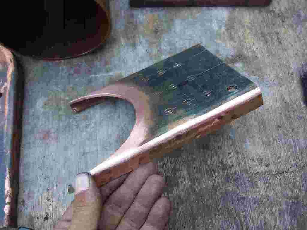
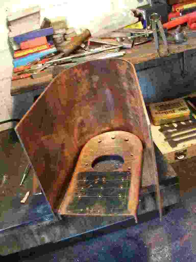
Picture shows the throat plate after dressing with a file and scotch bright you can just see the pop marks for the boiler stays and the drilling for the blow down valve that sits just above the foundation ring.
Dont worry about cleaning the copper too much at this stage its only going to tarnish as its worked and the pickle in sulphuric will do the best of the cleaning just prior to soldering.
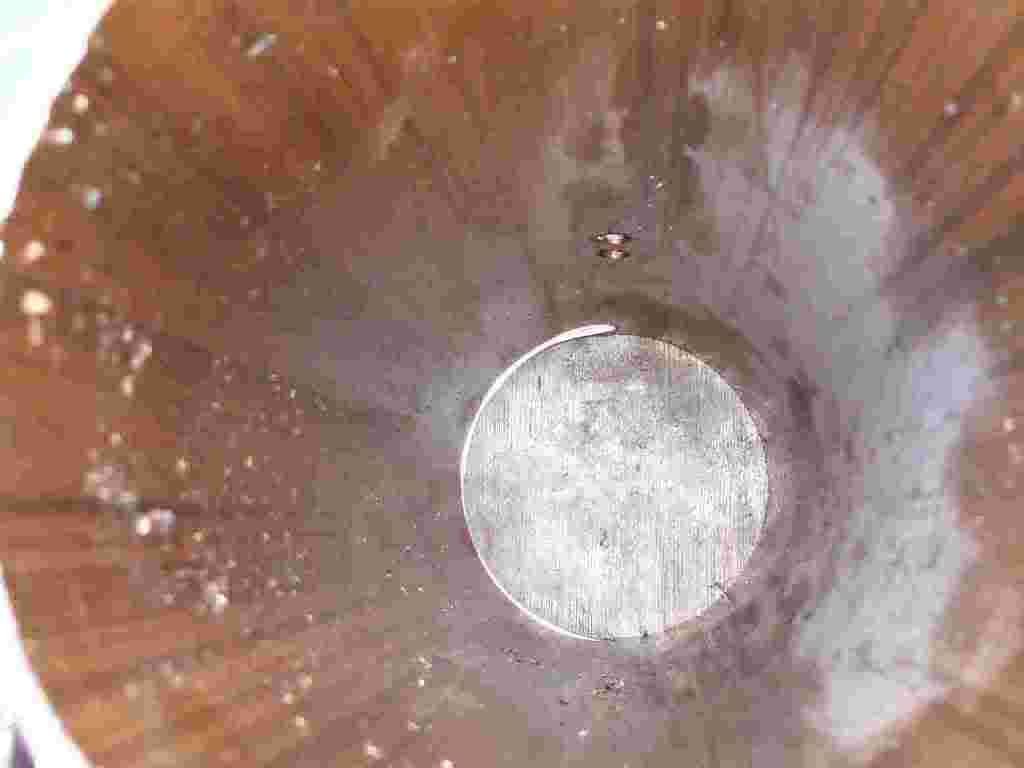
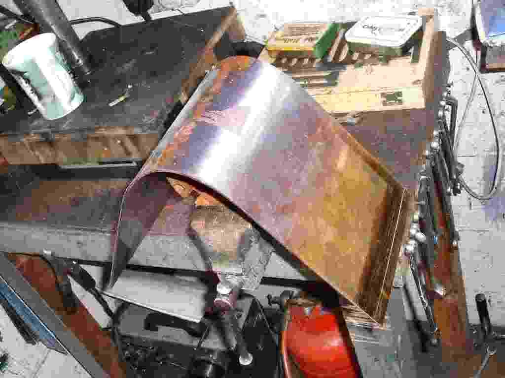
Picture shows the lip thats left inside the boiler tube on the throat plate for soldering. This lip will later be filed out after soldering the firts joint. I find it helps promote the flow of solder during the first heat up and joining.
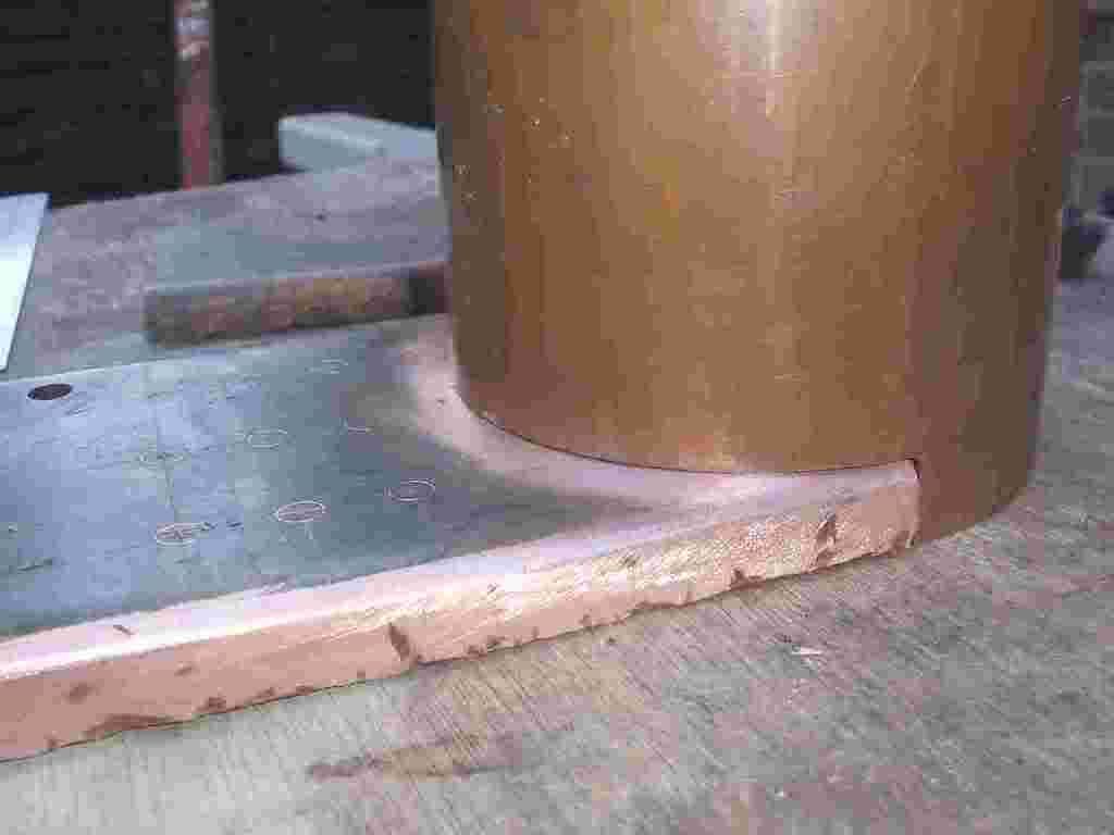
Picture shows the tube sat on the throat plate. This is the very first joint and great care should be taken to ensure that it goes together square and tight. Theres a lot of stress on the joint once the engines up and runing. The boiler is teh chasis of the engine after all.
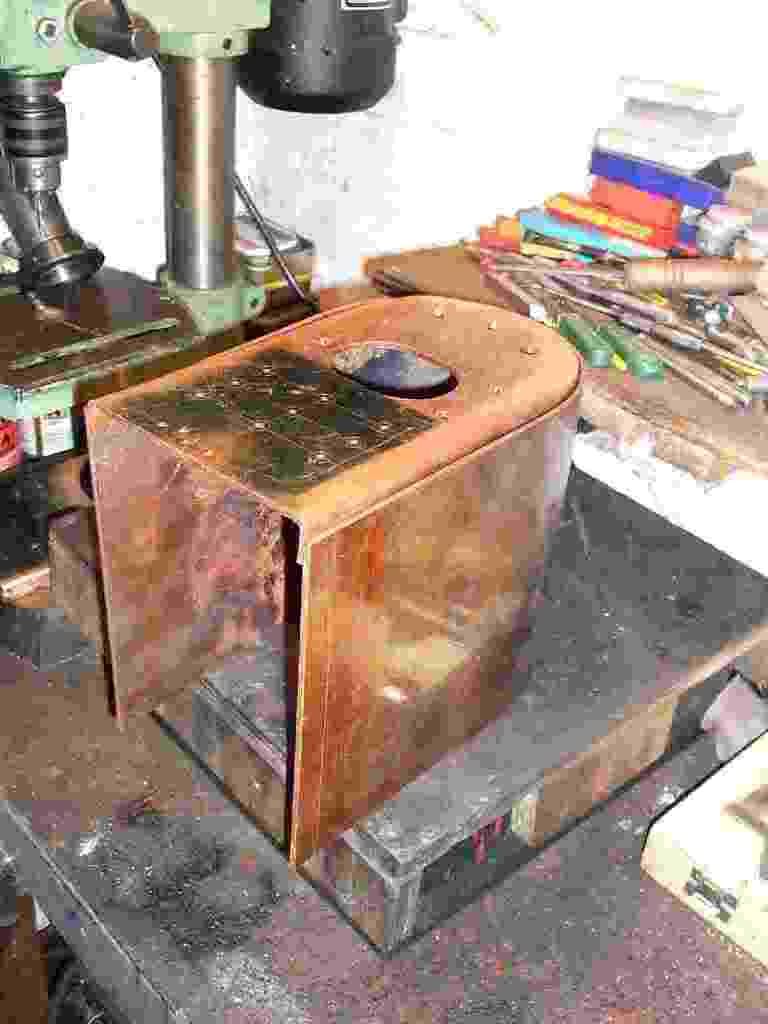
Picture should give an idea of the positioning of the throat plate on the tube. its about to go to pickle for the first time in 30% sulphuric to remove any oxides or grease. The flux will go on as soon as the boiler parts come out of the pickle.
This picture is just to give an idea of size and some of the parts in the boiler. from the left the parts are;
Front plate (called the backhead on a locco), tube plate, firebox tube plate, firebox rear plate and the throat plate.
__________________________________________________________
The following lets you see how the boiler copper is worked out to allow for the pressure.
P= Dx W.P. x F
----------------
Sx2xRxCxT
Where P = plate thicknes (barrel) in inches
S = Ultimate tensile strength in PSI (copper 25,000 PSI Steel 60,000 PSI)
F = Factor of safety from 6-10 as a rule 8
R = riveting allowance (.8 for welded brazed or silver soldered)
D = Diameter of barrel in inches
C = corrosion allowance (for steel only .25 inch and bellow .5 to .8)
temperature allowance (copper at 400F =.7 200F = .87)
W.P. = working pressure
All flat surfaces should be atleast 1/3 thicker than the boiler barrel. Stays should not exceed a pitch = to
tx800
_____
W.P.
t = thicknes of inner firebox wrapper
Firebox stays should be twice the thicknes of the inner firebox wrapper.
___________________________________________________________
The fire tubes are ready to flare and fit in the tube plates plus the copper for the remainder of the boiler is in the shop now and being cut into lumps. The copper for the wrappers is 10 gauge, to make the firebox and outer wrapper a sheet 17 inch x 27 inches is required.
Way i like to cut sheet like this is with a loose hacksaw blade, gives a bang on line cut with very little work to do to clean it up. Time to cut all the bits 6 hours.
____________________________________________________________
As a matter of course now on every copper boiler I make I flare one end of teh tubes to prevent them dropping through during silver soldering the firebox wrapper. trust me loosing a tube as you are soldering the firebox wrapper is a real pain in the backside and one to be seriously avoided. The little flare will stop this from happening and allow you to reposition any tube that moves during soldering with ease.
The flare should not be any larger than is required to stop te tube dropping through the hole. Also the flair should be inside the firebox and not allowed to extend into the water space.
Each tube is 20 gauge seamless copper tube, dont ever be tempted to use plumbing tube it just isnt designed to take the pressure!
The holes for the tubes are counter to good thinking cut slightly loose for the tubes to fit in. I start at a 5 thou over size hole. This sllows the silver solder to fill all around the tube and not just form a ring on one face of the tube plate. This is a very important factor in soldering the tubes in.
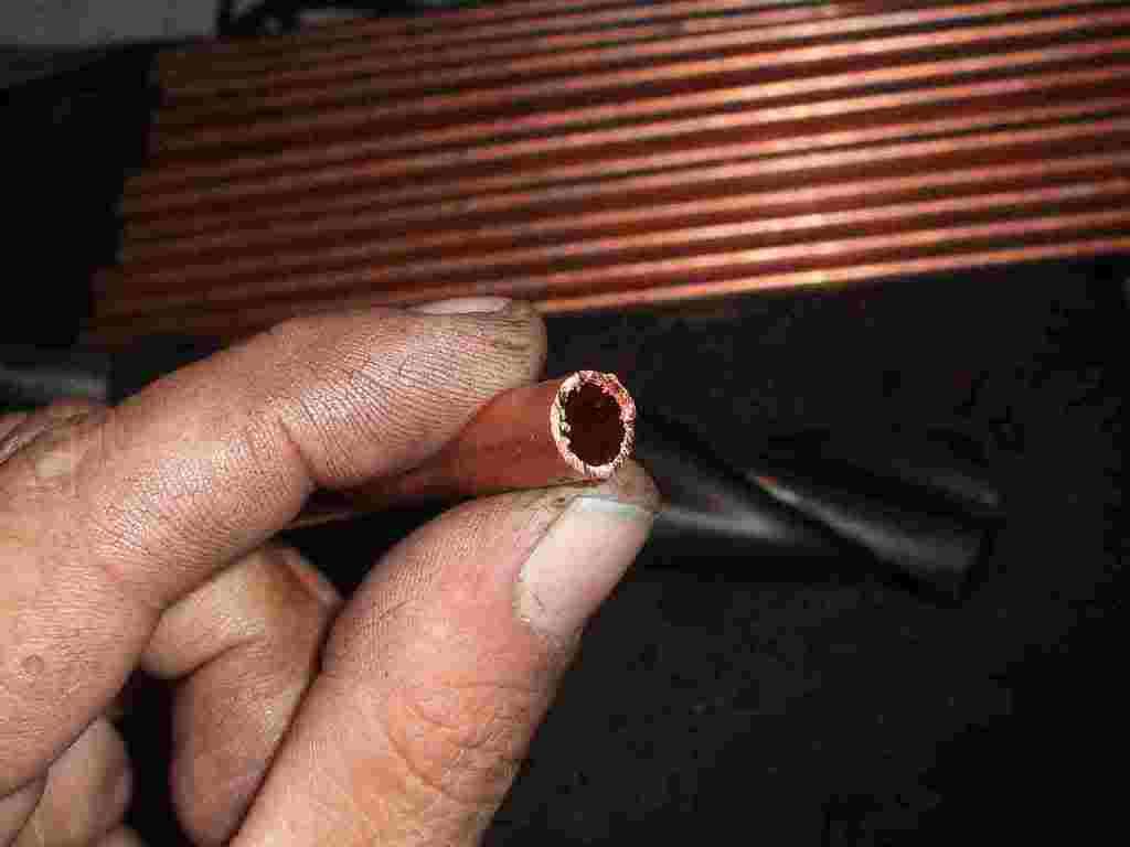
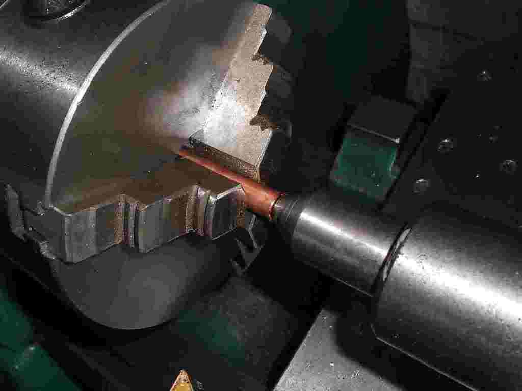
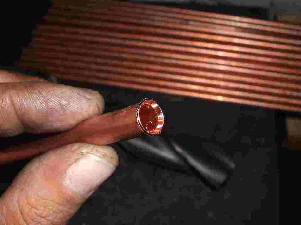
The first picture shows a raw tube unmachined, second picture shows a dead center being used to form the flare on the tube end, third picture shows the lite flare on one of the tube ends.
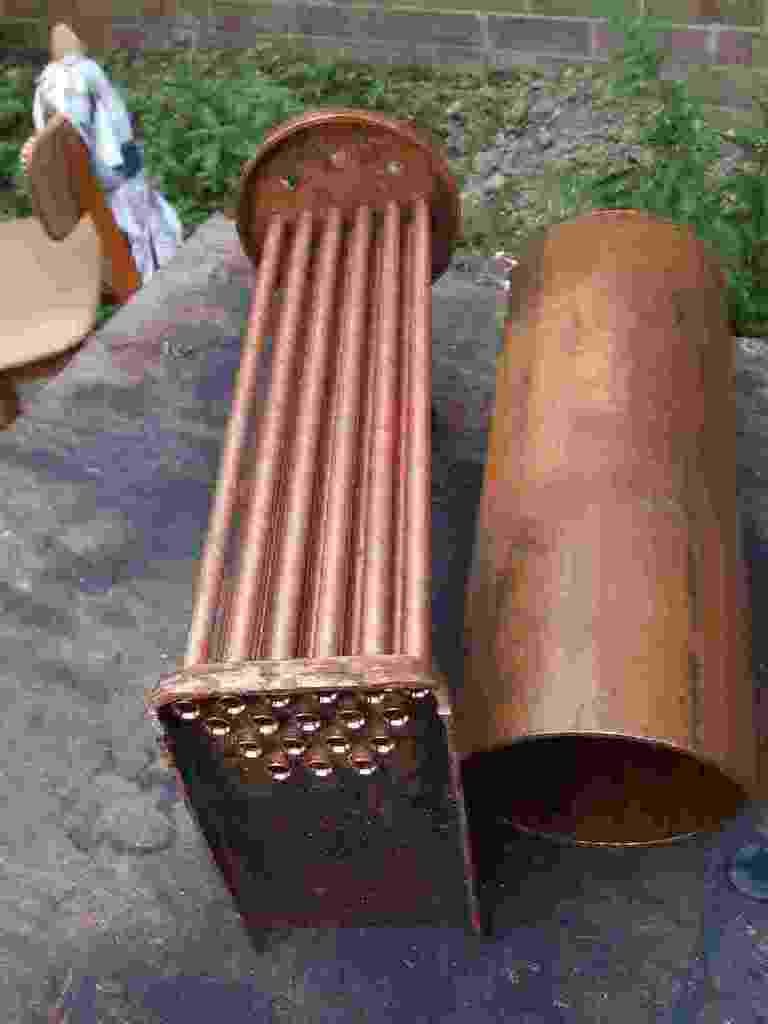
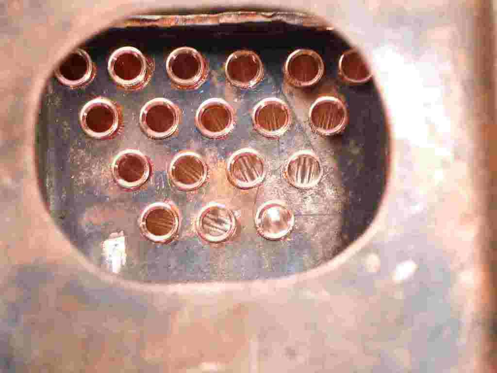
Next picture should give an idea of what the tubes will look like once inside the boiler. lasts one is a view in through the fire hole ring.
________________________________________________________
Now the wrapper sheets are cut the fun starts.
Copper work hardens and work hardens very fast just a few movements on a copper sheet that has been annealed is enough to get the copper to a point that it wont bend easily. Once its hard it must be annealed, annealing copper is easy just bring it up to cherry red with a good propane torch hold it there for a few seconds and then let it cool.
There are different schools of thought on quenching copper after annealing. Some will have it that air quenching is the only way and keeps the copper workable for longer. Others swear by water quenching also pointing to the way the black scale drops off in the water quench.
As far as i can tell the only advantage to water quench is the speed you can start reworking the copper. The scale isnt much of a problem just turns your hands to a colour your wife wouldnt want on her stockings.
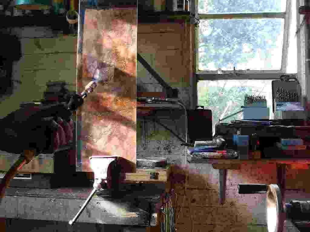
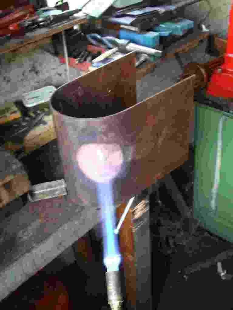
No matter what you use the sheet will need a lot of heat put into it to get it to cherry red. I use a large propane burner and a half pint blow lamp in addition on very big sheets.
Big word of warning on wrapper sheets, Dont use a hammer to help the bending! if you need to form a tight bend use a rawhide mallet or a block of pine side of teh grain on the copper. Copper in its soft state marks very easily and it looks like hell on a finished boiler if its full of dents and dings. Ok OK a set of sheet rolls would be the best way but 10 gauge wants some hefty rolls and not the ones you get from Chronos for 90 quid.
before you start set out any forms your going to use. For a wrapper this is as a rule just a stout lump of steel bar to form the bend round. On a more complex boiler wrapper a few odds and sods of 1/2 inch 78 and one inch bar will help. If your really fussy a wodden former can be made to the inside curve of the wrapper. To be honest this only really helps in checking the shape.
Pictures are pretty much plain to see so il spare you all the words.
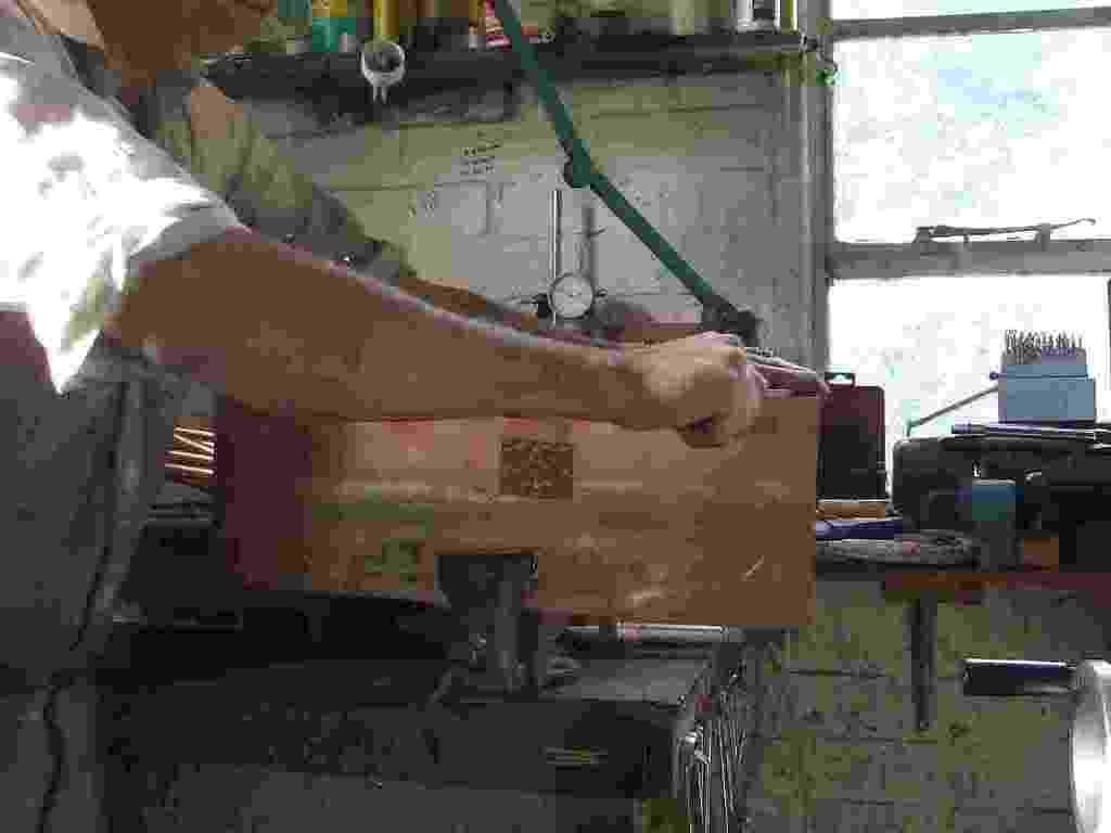
I think from the picture of the wrapper being draw filed youl get an idea of the amount of copper in this one and the heat thats required to anneal it!
first of many burns on this one, interesting how skin fizzes at 500 degrees almost like bacon cooking! Hmm bacon sandwich sounds in order!
Next post will be the firebox and il try to improve the image quality, crappy camera sorry.
Cheers Kevin
Well here goes, this is the build on my 2 inch traction engine boiler. Give some leaway to posting times and such as I hate typing.
A word on safety;
I am writing this as a description of the way I build a copper boiler and not as a full detailed lesson on how to make steam pressure vessels. please think about the following for a few moments before you think about trying the job.
Boilers are pressure vessels and have to be of a very high mechanical standard to be safe and insurable.
In the process of the build I will use sulphuric acid both dilute and 99% it burns either way and hurts like all hell if it splashes on you.
The soldering equipment is both propane and oxy acetalyn both are dangerouse and should be treated with a lot of respect. The chances of burning a hose are real and the end result is almost always very bad be carefull with what you are doing.
The only silver solder to use is Easy flow 2 it contains cadmium and all care should be taken not to breath the fumes.
During the soldering the copper hits 650 degrees in places and 250 degrees all over be aware that its easy to get a very bad very seriouse burn from the boiler gas jets or dripping molten brass/silver.
Ok the good bit.
The plates and tube have been ready for some time in the basic formed state. Now at the start of the assembly work
the plates and tube are made ready to fit together this is essential as during the forming of the plates some roll will be put on the flanges of the boiler plates.
Picture shows me bashing out the over bend on a 7/8th steel bar held in the vice. Once this has been done the flanges are filed and then given a clean up with scotch bright. Keep the flanges square and as dent free as you can it uses less solder and gives a good tight joint.
Picture shows the throat plate after dressing with a file and scotch bright you can just see the pop marks for the boiler stays and the drilling for the blow down valve that sits just above the foundation ring.
Dont worry about cleaning the copper too much at this stage its only going to tarnish as its worked and the pickle in sulphuric will do the best of the cleaning just prior to soldering.
Picture shows the lip thats left inside the boiler tube on the throat plate for soldering. This lip will later be filed out after soldering the firts joint. I find it helps promote the flow of solder during the first heat up and joining.
Picture shows the tube sat on the throat plate. This is the very first joint and great care should be taken to ensure that it goes together square and tight. Theres a lot of stress on the joint once the engines up and runing. The boiler is teh chasis of the engine after all.
Picture should give an idea of the positioning of the throat plate on the tube. its about to go to pickle for the first time in 30% sulphuric to remove any oxides or grease. The flux will go on as soon as the boiler parts come out of the pickle.
This picture is just to give an idea of size and some of the parts in the boiler. from the left the parts are;
Front plate (called the backhead on a locco), tube plate, firebox tube plate, firebox rear plate and the throat plate.
__________________________________________________________
The following lets you see how the boiler copper is worked out to allow for the pressure.
P= Dx W.P. x F
----------------
Sx2xRxCxT
Where P = plate thicknes (barrel) in inches
S = Ultimate tensile strength in PSI (copper 25,000 PSI Steel 60,000 PSI)
F = Factor of safety from 6-10 as a rule 8
R = riveting allowance (.8 for welded brazed or silver soldered)
D = Diameter of barrel in inches
C = corrosion allowance (for steel only .25 inch and bellow .5 to .8)
temperature allowance (copper at 400F =.7 200F = .87)
W.P. = working pressure
All flat surfaces should be atleast 1/3 thicker than the boiler barrel. Stays should not exceed a pitch = to
tx800
_____
W.P.
t = thicknes of inner firebox wrapper
Firebox stays should be twice the thicknes of the inner firebox wrapper.
___________________________________________________________
The fire tubes are ready to flare and fit in the tube plates plus the copper for the remainder of the boiler is in the shop now and being cut into lumps. The copper for the wrappers is 10 gauge, to make the firebox and outer wrapper a sheet 17 inch x 27 inches is required.
Way i like to cut sheet like this is with a loose hacksaw blade, gives a bang on line cut with very little work to do to clean it up. Time to cut all the bits 6 hours.
____________________________________________________________
As a matter of course now on every copper boiler I make I flare one end of teh tubes to prevent them dropping through during silver soldering the firebox wrapper. trust me loosing a tube as you are soldering the firebox wrapper is a real pain in the backside and one to be seriously avoided. The little flare will stop this from happening and allow you to reposition any tube that moves during soldering with ease.
The flare should not be any larger than is required to stop te tube dropping through the hole. Also the flair should be inside the firebox and not allowed to extend into the water space.
Each tube is 20 gauge seamless copper tube, dont ever be tempted to use plumbing tube it just isnt designed to take the pressure!
The holes for the tubes are counter to good thinking cut slightly loose for the tubes to fit in. I start at a 5 thou over size hole. This sllows the silver solder to fill all around the tube and not just form a ring on one face of the tube plate. This is a very important factor in soldering the tubes in.
The first picture shows a raw tube unmachined, second picture shows a dead center being used to form the flare on the tube end, third picture shows the lite flare on one of the tube ends.
Next picture should give an idea of what the tubes will look like once inside the boiler. lasts one is a view in through the fire hole ring.
________________________________________________________
Now the wrapper sheets are cut the fun starts.
Copper work hardens and work hardens very fast just a few movements on a copper sheet that has been annealed is enough to get the copper to a point that it wont bend easily. Once its hard it must be annealed, annealing copper is easy just bring it up to cherry red with a good propane torch hold it there for a few seconds and then let it cool.
There are different schools of thought on quenching copper after annealing. Some will have it that air quenching is the only way and keeps the copper workable for longer. Others swear by water quenching also pointing to the way the black scale drops off in the water quench.
As far as i can tell the only advantage to water quench is the speed you can start reworking the copper. The scale isnt much of a problem just turns your hands to a colour your wife wouldnt want on her stockings.
No matter what you use the sheet will need a lot of heat put into it to get it to cherry red. I use a large propane burner and a half pint blow lamp in addition on very big sheets.
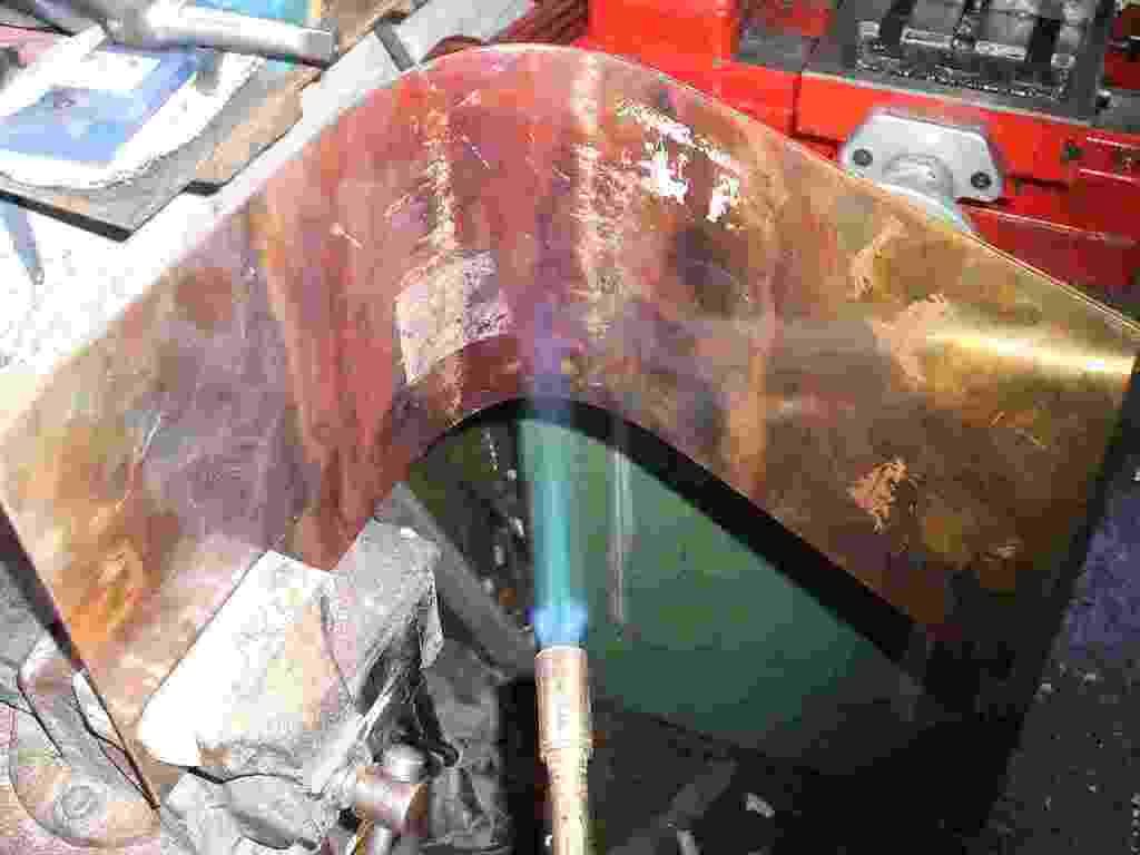
Big word of warning on wrapper sheets, Dont use a hammer to help the bending! if you need to form a tight bend use a rawhide mallet or a block of pine side of teh grain on the copper. Copper in its soft state marks very easily and it looks like hell on a finished boiler if its full of dents and dings. Ok OK a set of sheet rolls would be the best way but 10 gauge wants some hefty rolls and not the ones you get from Chronos for 90 quid.
before you start set out any forms your going to use. For a wrapper this is as a rule just a stout lump of steel bar to form the bend round. On a more complex boiler wrapper a few odds and sods of 1/2 inch 78 and one inch bar will help. If your really fussy a wodden former can be made to the inside curve of the wrapper. To be honest this only really helps in checking the shape.
Pictures are pretty much plain to see so il spare you all the words.
I think from the picture of the wrapper being draw filed youl get an idea of the amount of copper in this one and the heat thats required to anneal it!
first of many burns on this one, interesting how skin fizzes at 500 degrees almost like bacon cooking! Hmm bacon sandwich sounds in order!
Next post will be the firebox and il try to improve the image quality, crappy camera sorry.
Cheers Kevin
