ex-Gooserider
Maker of things
- Joined
- Oct 6, 2015
- Messages
- 7
- Reaction score
- 0
Not exactly an engine building question, but definitely a modification challenge....
I am in the process of building an adaptive electric skateboard for a wheelchair using friend. He has supplied many of the parts, I mostly need to design and build the brackets that hold everything together.
I have found one big problem with the parts I was given, IMHO because of lousy workmanship on the part of the original supplier - who is not terribly helpful.... :wall:
The motor is an electric 'outrunner' style - the sort often used on BIG RC model planes. The shaft on it has a keyway, that is intended to match the keyway on the supplied pulley.
The problem is that the supplied key is 3mm^2 X 16mm, which is (I'm told) one of the standard metric sizes. It fits perfectly in the pulley, but the keyway in the motor shaft is only about 2.85mm X 14.5mm, and the key won't fit in the shaft at all.
The supplier's "answer" is to grind the key to fit, but aside from not wanting to be making a non-standard key that will be a pain to replace if it is ever lost, that would mean having a poor fit in the pulley....
Seems to me like the better solution is to try and enlarge the keyway in the shaft to the CORRECT size, so that stock keys can be used....
It would be easy enough to fix the pulley by going at it with some needle files, but the best way to deal with the shaft is less obvious...
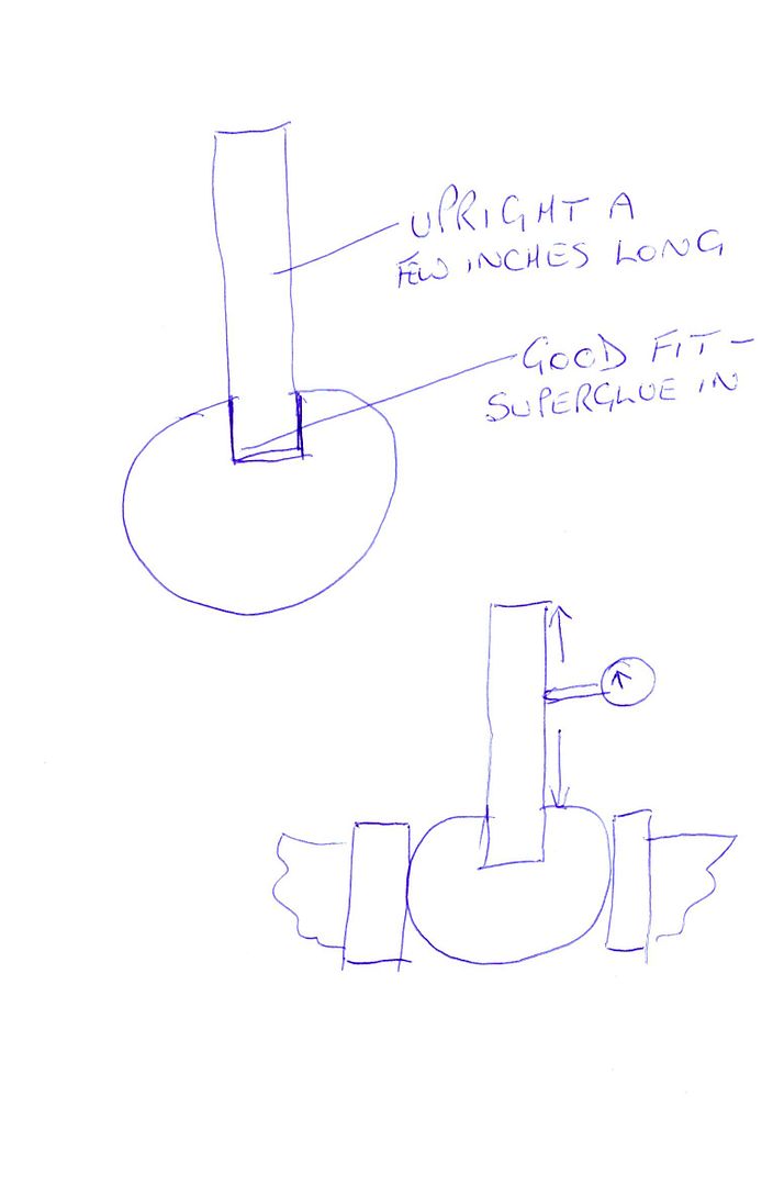
The shaft can be removed from the motor without much hassle, and I have access to a Sharp mill (Bridgeport clone) with 2-axis CNC / DRO function. My thought is to clamp the shaft in the vice w/ a V-block after trying to get the existing keyway as vertical as possible, and then try to mill it wider...
Any better / alternative ideas?
Any suggestions about the best way to get the existing keyway vertical that are more precise than the old 'Mark 1 eyeball'?
Also my smallest mill bit is 3mm. I know that ideally one should cut slots with a bit that is narrower so as to only be cutting one side at a time, but if I just drill down with the bit every couple of mm, and then run it back and forth to clean up, will that be good enough?
Thanks,
Ex-Gooserider
I am in the process of building an adaptive electric skateboard for a wheelchair using friend. He has supplied many of the parts, I mostly need to design and build the brackets that hold everything together.
I have found one big problem with the parts I was given, IMHO because of lousy workmanship on the part of the original supplier - who is not terribly helpful.... :wall:
The motor is an electric 'outrunner' style - the sort often used on BIG RC model planes. The shaft on it has a keyway, that is intended to match the keyway on the supplied pulley.
The problem is that the supplied key is 3mm^2 X 16mm, which is (I'm told) one of the standard metric sizes. It fits perfectly in the pulley, but the keyway in the motor shaft is only about 2.85mm X 14.5mm, and the key won't fit in the shaft at all.
The supplier's "answer"
is to grind the key to fit, but aside from not wanting to be making a non-standard key that will be a pain to replace if it is ever lost, that would mean having a poor fit in the pulley....Seems to me like the better solution is to try and enlarge the keyway in the shaft to the CORRECT size, so that stock keys can be used....
It would be easy enough to fix the pulley by going at it with some needle files, but the best way to deal with the shaft is less obvious...
The shaft can be removed from the motor without much hassle, and I have access to a Sharp mill (Bridgeport clone) with 2-axis CNC / DRO function. My thought is to clamp the shaft in the vice w/ a V-block after trying to get the existing keyway as vertical as possible, and then try to mill it wider...
Any better / alternative ideas?
Any suggestions about the best way to get the existing keyway vertical that are more precise than the old 'Mark 1 eyeball'?
Also my smallest mill bit is 3mm. I know that ideally one should cut slots with a bit that is narrower so as to only be cutting one side at a time, but if I just drill down with the bit every couple of mm, and then run it back and forth to clean up, will that be good enough?
Thanks,
Ex-Gooserider