Ball Joints

Home Model Engine Machinist Forum

Help Support Home Model Engine Machinist Forum:

This site may earn a commission from merchant affiliate links, including eBay, Amazon, and others.

Captain Jerry

Project of the Month Winner!!!
Project of the Month Winner
Joined
Dec 2, 2008
Messages
971
Reaction score
8
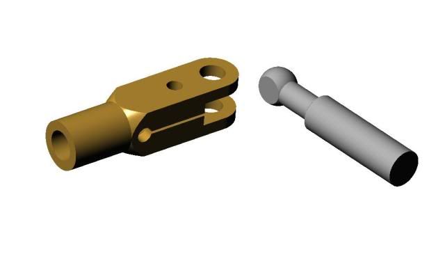
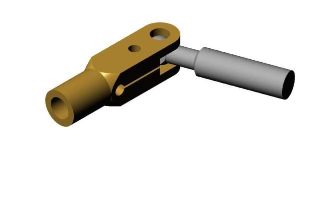
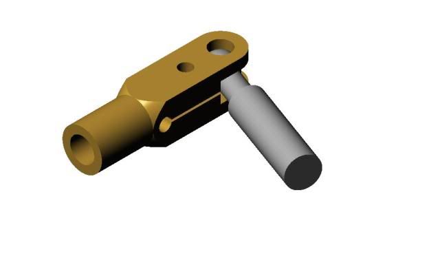
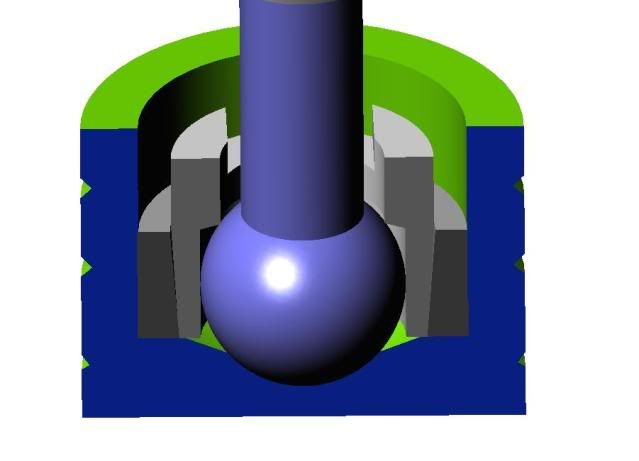
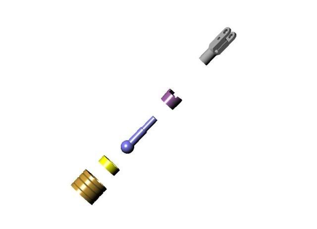
How to make a ball joint. I needed to make ball joints for the pistons in my 6 cylinder wobble plate engine and I decided to make this a separate topic since there are other applications where this might be used. In a wobble plate engine, the piston rod cannot use a regular wrist pin because it must offset in all planes, not very much, a matter of a few degrees, but the action must be free and with no end play. To be really useful, the design should allow for wear adjustment.

The engine thread is here: http://www.homemodelenginemachinist.com/index.php?topic=6707.msg92205#msg92205

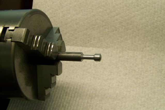
The first step is to produce a ball on the end of the piston rod. The piston diameter is .625" so decided on a ball diameter just less than half that. I started with a length of 3/8" CRS from the hardware store. I chucked it up in the lathe with about 2" extended to keep my hands at a distance from the chuck.


Pistonballjoint002.jpg


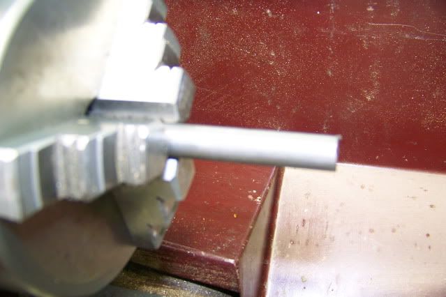
I turned this down to .300" for a length of about one inch.


Pistonballjoint003.jpg


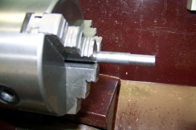
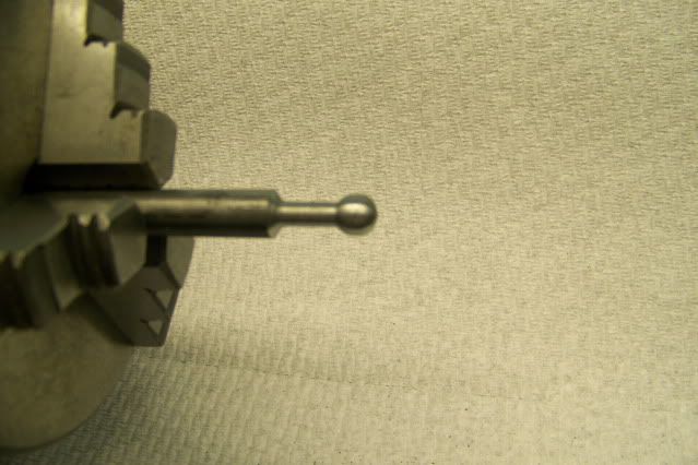
Moving in from the end of the rod, I reduced the diameter to .1875" leaving a lump on the end from which to fashion a ball.


Pistonballjoint005.jpg


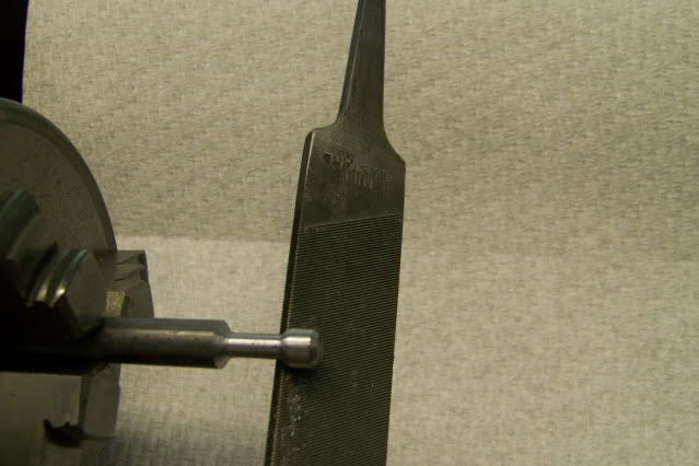
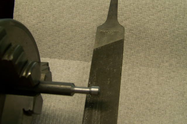
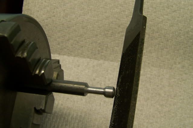
If I had a ball turner, I would have used it but I don't so I used a mill on a stick (a technical term for a file that I picked up on this forum). I use the file to shape the ball freehand. In order to see the ball as it takes shape, I use the file under the stock with the tang facing to the rear. I used to be a fairly competent wood turner, giving exhibitions a state and county fairs throughout the east coast. I could turn a nearly perfect 2" ball on a piece of sugar pine in less than 1 second with two passes of the scew chisel, one to the right and one to the left, so I guess I still have a pretty good eye but I think anyone could do as well with just a little practice. It took about 30 seconds with the file to produce the rough ball on the end of the rod.

Pistonballjoint006.jpg


Pistonballjoint007.jpg


Pistonballjoint008.jpg


Pistonballjoint009.jpg


The rough ball was then ground to precise sphere and polished in the lathe. I made a special grinding tool from another piece of the steel rod by facing the end and drilling 9/32" diameter hole .25" deep and chamfering the edge. The hole was then charged with valve grinding compound and chucked in my electric drill.

With the lathe running at about 800 RPM and the drill running about 1200 RPM, the charged end of the grinding tool is applied to the rotating ball with moderate pressure and moved from side to side, keeping the ball in the charged depression.

Pistonballjoint010.jpg


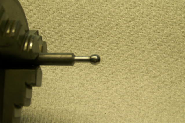
For the first few seconds, it will look like the grinding to is only making contact at two places as shiny rings appear on the ball. These are the high spots. As the high spots are ground down, the shiny rings get wider. Keep moving the tool back and forth. you can go from almost in line with lathe axis to the right and then to the left till the grinding tool contacts the rod. Within about a minute, certainly less than two, the shiny lines have widened to the point that they merge and the ball is a sphere. Wipe the ball clean with a little turpentine and clean out the charged end of the tool. Take the tool out of the drill and with the lathe turning take a strip of 1200 wet/dry paper an lay it over the ball and press the tool to the ball trapping the paper between the tool and and the ball. Move it side to side as you did while grinding and stop when you are satisfied with the polished ball. Twenty or thirty seconds.

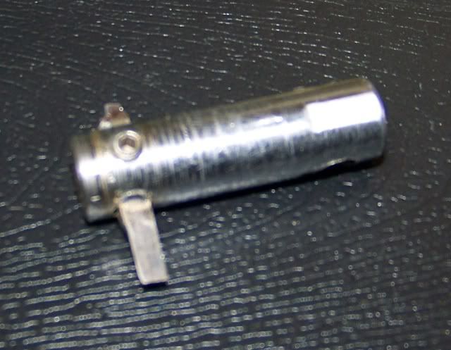
Here is the finished results. Five minutes or less.

Pistonballjoint013.jpg


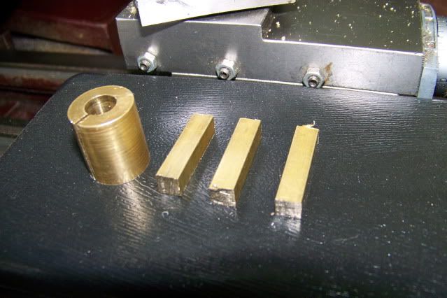
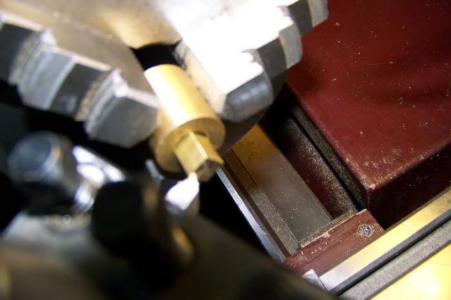
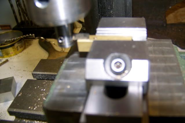
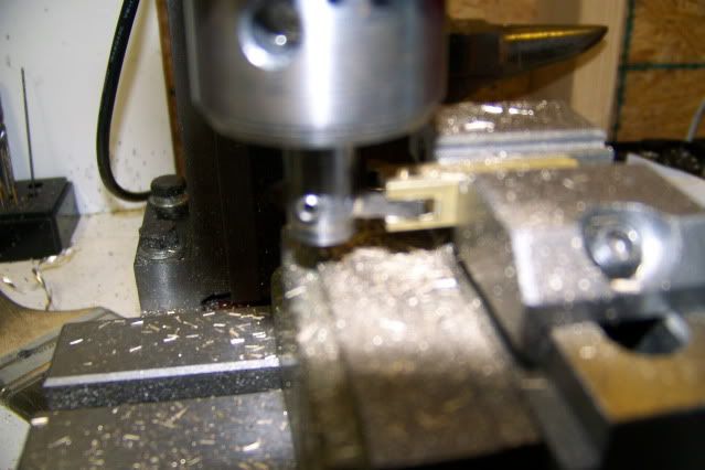
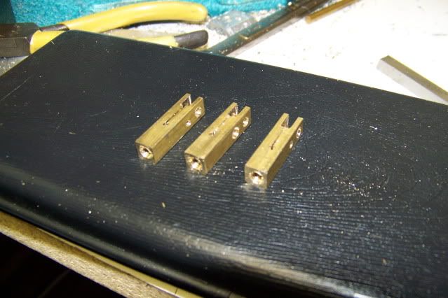
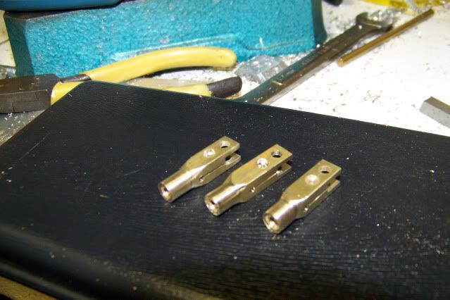
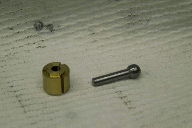
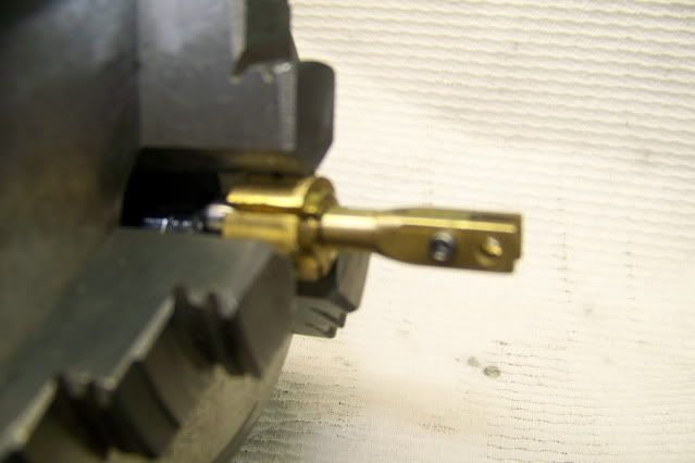
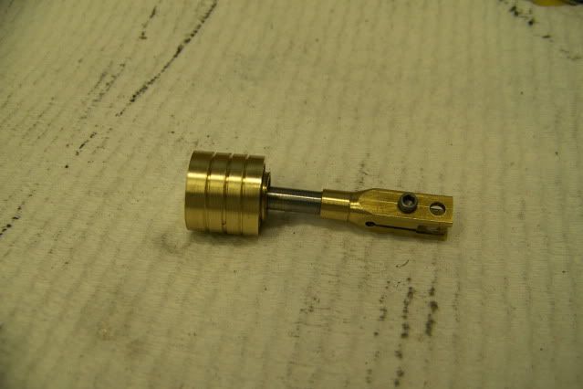
Now turn the 1/8" part of the rod to finished length and part it off. The piece of brass in the pic is a fixture to let me work the other end of the part. It is sized to allow 5 more pieces to be finished to the same length.

Pistonballjoint014.jpg


Pistonballjoint015.jpg


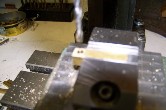
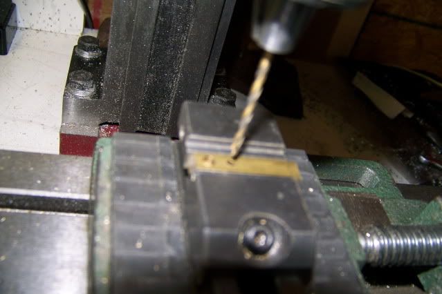
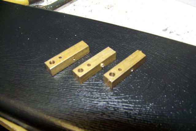
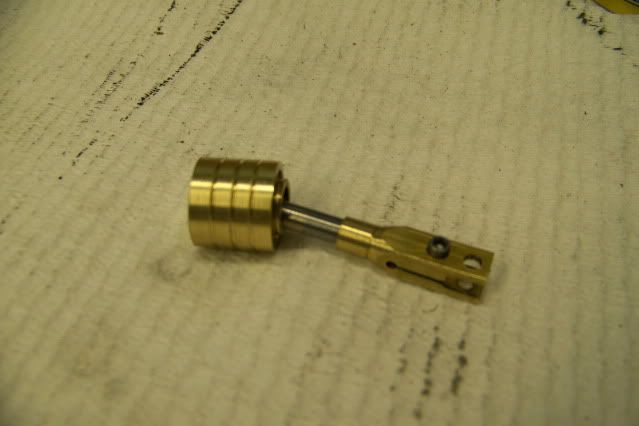
I seem to have lost a picture here but the next step is to thread the exposed end of the rod for #8-32. The next picture shows the clamp end of the rod screwed onto the threaded part and the lined up with its sisters.

Pistonballjoint016.jpg


Pistonballjoint018.jpg


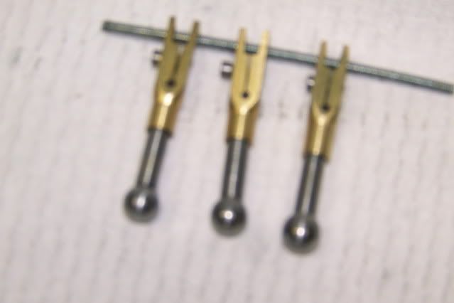
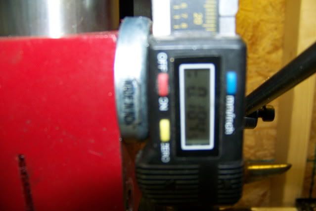
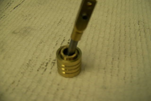
My appologies for the photo quality. Not one of my strong suits. Difficult to get focused.

It is now getting late so I will continue tomorrow with the socket and retainer. That's a little more complicated.

Jerry
 
Thats a cool way to make a "ball on a stick" and it looks faster than setting up a ball turner. Two thoughts:
1) Hardware store steel is, in my experience, absolute crap. I'm not sure what it's made from, but I've had poor luck machining it.
2) The countless millions of COX model airplane engines have ball joints at the piston/con-rod interface. The inside top of the piston has a socket into which the ball on the con-rod was inserted and, using a special tool, the socket was swaged over the ball. There was enough material spring-back to ensure that the fit was loose enough to move, but still tight. There were aftermarket tools for the enthusiast to reseat the swage joint if it became loose over time. As I recall the tool was made by KIRNCRAFT and there may still be some info about the whole business on the net.
 
Ed

I agree with the hardware store steel is crap, but even with that stuff, it isn't to hard to produce a good result.

As to the Cox engines, were the pistons aluminum or what? I have tried staking the edge of the the seat with a punch but found it pretty unreliable and if it comes apart in use, things could get ugly. The method I used involves a threaded retainer that can be adjusted for wear and gives a 360 degree contact.

I'm called for dinner so I'll get back to this later with pics.

Jerry
 
I haven't figured out how to post a .pdf file except as an attachment so download the attachment. It is a sectional view of a piston with a ball joint. It will be easier to understand the following posts if you have an understanding of the whole assembly.

EDIT:

I figured out how to post them as JPG :

RodinShell.jpg


The second Pic is an exploded

PistonBallJointAssembly.jpg


Jerry

View attachment Rod in Shell.pdf

View attachment Piston Ball Joint Assembly.pdf
 
For reference, the parts shown in the exploded assembly are, from left to right:

1: Piston, Brass, 5/8" Dia. 1/2" length ID 1/2" to depth of .375". The piston is first drilled with a 3/8" bit to a depth of .400" (to drill point) and then bored to a dia of .500" and depth of .400", leaving a flat bottom shoulder.

2: Threaded Insert. Brass, 1/2" O.D., .300" length, Threaded inside 1/8" Pipe Tapered 27 TPI (NPT). The insert is fixed in the piston with red permanent loctite. It should be well seated on the flat bottom shoulder above. If you want to attempt internal single point threading all the way to the bottom and eliminate the insert, go ahead, and let me know how it worked out. Its beyond me.

3: Ball end .280 Dia (approx) from previous post.

4. Retainer, Brass, Outside 1/8" Pipe, Tapered, 27 TPI (NPT). ID at upper end 1/4" ID at lower end is 19/64" (.29874). When the ball is seated in the conical depression, the retainer is screwed into the insert. It should screw all the way down to the shoulder in the piston, without binding the ball. If it makes contact with the ball, the fit can be adjusted by drilling the piston slightly deeper. This can be done without removing the threaded insert using the 19/64" bit. If there is too much end play, the retained can be shortened with a few strokes on the file. I find this easier to do if the file is laid flat on the bench and the retainer stroked across it. This is also the procedure for adjusting for wear. The desired fit at this point is slightly snug. That is, with the retained firmly tightened, the rod should be able to me moved by hand but not really free. At this point, the ball is making contact with the flat part of the conical depression left by the drill bit end. It has not been seated. I do this by griping the rod in my drill press chuck and holding the piston in my hand as the drill press runs. Applying upward pressure seats the ball in the piston and applying downward pressure helps seat the ball in the retainer. This is aided by a few drops of oil and maybe a bit of polishing compound. The piston should be wobbled during this process. Be sure and remove the retainer and rod from the piston and clean it well after this operation. Be careful reinserting the retainer as it is very easy to cross thread these fine threads. It should screw in very easily until it botoms on the piston shoulder and then can be torqued against the shoulder without binding the ball.

5. Clamp end. This part of the rod is specific to the engine and will not be detailed at this point. Check the engine build thread if you are interested in this part.

The adjusting and seating part of this might seem to be a little bit fiddly, but remember, the balls were filed and polished by eye. The polishing procedure ensures that they are very nearly spherical but the diameter is anybody's guess.

I have a great fear of this computer crashing during the editing of any long post, so I'm going to file this post now before it is all lost and start another post with pictures immediately. It may be completed by the time you read this.

Jerry

 
This going to be short. I didn't realize how late it had gotten and how tired I was so here are a few pictures, as promised. If I can, I will edit this in a few days and add some description, but if you refer to the above post you should be able to figure out what is going on.

Insert being bored.

Pistonballjoint019.jpg


Insert being threaded.
Pistonballjoint021.jpg


Insert in piston bore. Note flat bottom for retainer to seat on.

Pistonballjoint022.jpg


Pistonballjoint023.jpg


Pistonballjoint024.jpg


Pistonballjoint025.jpg


Pistonballjoint025.jpg


Pistonballjoint028.jpg


I just noticed that this does not show the lugs that should be milled on the top of the retainer so that the retainer can be torqued down with a special wrench. If you look at the section view in the first .pdf above, you can see the milled slot on the retainer for the wrench.

I'm going to be away from the shop for a few days. I'll check in when I get back.

Jerry
 
Captain Jerry said:
As to the Cox engines, were the pistons aluminum or what?
They were turned from steel (including the ball socket) on a screw machine, copper plated, the plating ground off the skirt, case-hardened (the plating prevented the ball socket from being hardened so it wouldn't crack when swaged later) then the skirt finish ground to the final (amazingly close) tolerance.

The entire line of Cox engines were made to very close & consistent tolerances by the millions starting in the 50's with nary a CNC machine in the place. :eek: The machining areas were kept at a very narrow temperature range 24/7 to help accomplish the tolerances & fits needed.
 
I dont need to make a ball-joint but...wow, this is some neat stuff! A kudos point for you sir.
 
I decided to detail the clamp end of the con rod here, even though nobody asked. This is also a ball joint but of a different type. This joint, like the one above must be able to articulate in all planes through fairly small angles EXCEPT for one plane in which it must be able to articulate at least 40 degrees. The design actually allows a range of more than 300 degrees but in this application it only needs to move 40 degrees. That is the ofsett angle of the ball bearing wobble plate for this engine.

The first pic is of the two pieces separated. Clamp on left, spider arm or right. The ball is produced as above except that the diameter of the ball is 3/16". Note the flat on the ball. It is milled or filed after the ball is polished. You might think that this would cause lumpy movement, but in fact, the flat never contacts the clamp face. It is there to aid assembly. The clamp only contacts the ball on the shoulders.

clampandRodapart.jpg


The next pic shows the parts assembled and in the position of Top Dead Center.

clampandRodTDC.jpg


And then at Bottom Dead Center having articulated 40 degrees.

clampandRodBDC.jpg


Real pics follow in next post.

Jerry
 
The first pic is three pieces of square brass rod, 1/4" x 1" and a piece of brass drilled and sawed lengthwise for a holding fixture for the three jaw chuck:

March1011.jpg


Then with the rod and fixture in the chuck to be faced and drilled and tapped for #8-32 to accept the piston rod.

March1012.jpg


Then it is moved to the mill to drill two holes, one is 1/8" to hlod the ball, and one is 5/32 for a #2-56 socket head screw to adjust clamp tension. A second 5/32" hole is drilled in the other face of the piece to form the bottom of the clamp slot.

March1013.jpg


March1015.jpg


March1016.jpg


The next pic is a form tool to cut the slot in the end of the clamp, It is ground from 1/8" square tool steel and held in a short length of 3/8" CRS.

March1017.jpg


The bottom of the cutter is touched and the DRO zeroed and then the piece is backed off and the tool is lowered 3/16" (.1875) using the DRO.

March1020.jpg


March1022.jpg


This will center the 1/8" slot leaving two 1/16" sides to hold the ball. In this case, because the vise jaws are parallel with the X axis, milling will be done by advancing the piece into the cutter using Y axis feed. The let me complete the cut to full depth in one pass. If I had tried to plunge the piece endwise into the cutter along the X axis, I would have had to make many passes to reach depth. If at first this seems backward to you, think a little more.

March1025.jpg


I'm going to post this now and continue in the next post

Jerry
 
Continuing...

I seem to be missing a couple of the pictures or maybe I never took them but the next step is to replace the form cutter with a slitting saw and saw a slot down to the relief hole. Check the first 3D model above. Here are three pieces so far.

March1034.jpg


The pieces are then returned to the lathe and profiled.

March1035.jpg


To assemble, rotate the rod so that the flat on the end of the ball is parallel to the slot and push the ball into the end of the clamp with firm pressure. The clamp screw must be complete loosened to allow the clamp to expand. The ball should snap in with a sharp click. At this point, it will be fairly tight. To seat the joint, grab the rod in the three jaw and hold the clamp while the lathe is run. If you are uncomfortable this close to the lathe chuck, you can do this in the mill or drill press. As always, no gloves, no necktie, no loose sleeves, no loose hair and no distraction. You can add a little oil and polishing compound to the joint as it turns. You can tighten the clamp screw to achieve a good close fit but do not close the clamp completely. You want to leave room to adjust for in-use wear.

The necktie comment is just a rememberance of my own father, who passed on many years ago. I don't think I ever saw him without a necktie, whether working on the car or fishing. We didn't have machine tools but I'm sure he would have loved it, necktie and all.

I may have skimmed over this a little lightly so if anybody wants clarification, just ask.

Bye the way. These designs are just the way that I found to solve the problem. They are not the only way to make ball joints. If you have another method, PLEASE add to this thread. I would be gratefull for any improvements or alternatives.

I am aware of a few drawbacks of my design that I would like to improve on. The piston and retainer are relatively heavy. Aluminum might be a better choice. I'll experiment.

I looked at the method used by Cox as posted in an earlier reply. They used a copper plated steel piston with an integral socket that was swaged over the ball with a special tool. I could not find details on the tool but I think I can figure what it looked like. Their design was probably lighter and cheaper to produce with automated equiment but I doubt that I could duplicate it.

If I were to use a ball mill to form the base and retainer surfaces instead of a drill bit, fit and wear might be improved but unless I could hold tighter dimension on the ball, it probably wouldn't make any difference.

Best to all,
Jerry

Jerry
 
Jerry,
Sorry I didn't follow up sooner on the COX piston info. Thanks to the person who did. The tool was pretty simple consisting of a piece of bar stock with a slot in it lengthwise to clear the conrod although it didn't clear the big end as I recall so the rod lay in the slot at an angle. The end that did the work was just a conical feature that compressed the open end of the tubular feature inside the piston. Now, this tool was just for tightening up loose joints in the field and I have no idea how it was accomplished in production. If you think about it, the ball and socket arrangement is only going to have a line of contact at any given moment. Even with the finest machining available the socket has to be a little bigger than the ball to allow things to move. I guess after a while the form of the ball or socket would tend to wear to match the mating part, but, of course, the whole thing would get looser as that happened.
In the case of the COX engines, they were drowning in castor oil all the time so they were well lubricated. That said, I can remember running them at 25,000 RPM and, somehow, they stayed together so they must have done something right. There was mention of the tolerances in an earlier post and, as I recall, they were controlling clearances down to about 25 millionths of an inch. The cylinder bores were slightly tapered so that when things heated up and the top was hotter than the bottom, the cylinder was not tapered courtesy of the difference in thermal expansion between the hot top and the cooler bottom. All that for $3.00 at the hobby shop. Amazing!!!
Cox is still around. They were owned by ESTES Industries (model rockets) who pretty much ran it into the ground with the help of video games and the like. They were recently purchased by some zealots in Canada who are trying to keep it going in some form. Not sure if they are making engines again or just bleeding off old stock and parts.
More than you needed/wanted to know I'm sure.
 
Hi Jerry,

This is really some great looking stuff you have coming along here. If I may be permitted to go off-topic a little bit...In one of your pics I see what appears to be a sort-of homemade DRO held on with magnets. Is this what I see or am I completely off? If I am indeed right, how do the magnets perform? Are they secure, do they "creep" at all, what size/type magnets are they?
 
Chris

The magnets are common elcheapo ceramic magnet $.99/pair at Harbor Freight. They are shaped like a big fat washer in a stamped steel cup with a hole in the middle for a screw. The scale is a cut-off $10 digital caliper special from HF. The mill that you see in the pic is a HF micro-mill Seig X1. This mill uses a screw to raise and lower the head for course adjustment, and then uses a quill feed like a drill press for the fine adjustment. The magnet is stuck on the side of the head casting and the slider is pushed up against the bottom of the motor mount. The force is so light that creep is very unlikely. The caliper only advances on the down stroke. If I overshoot, I raise the quill and push the slider up to meet it and then come down more carefully.

Ed

Thanks for the Cox info. That's about what I thought except for the big end clearance. With a two part rod like I am using, that is not a problem. The tool could be just a tube of the right size with the working end chamfered on the inside. At some point I may try something like that with an aluminum piston. Aluminum might not work out for the retainer but It would definitely improve the weight situation.

Jerry
 

Latest posts

Back
Top