
You are using an out of date browser. It may not display this or other websites correctly.
You should upgrade or use an alternative browser.
You should upgrade or use an alternative browser.
Arnold's tooling odds 'n ends
- Thread starter arnoldb
- Start date


Help Support Home Model Engine Machinist Forum:
This site may earn a commission from merchant affiliate
links, including eBay, Amazon, and others.
arnoldb
Well-Known Member
- Joined
- Apr 8, 2009
- Messages
- 1,792
- Reaction score
- 12
:big: Thanks Dave - now, when's your birthday then ?
Back to tooling for a change - just a minor bit, but useful none-the-less.
As said, I love the tooling plate, and it would be extremely useful if it could be mounted to my rotary table easily.
All of my "small" clamping kit is based around M6 threads, so the holes in the tooling plate are all threaded M6, but so are all the T-nuts I use on my Myford and the rotary table.
This means I can't directly bolt the tooling plate to the rotary table, so I modified a couple of high tensile cap screws of appropriate length by turning of a section of thread long enough to allow it, with a washer, to screw through the tooling plate and then spin freely in the hole once the thread clears:
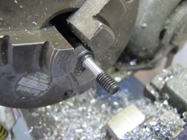
There's no need to turn it down right to the head; the bit left is just thinner than an ordinary M6 washer.
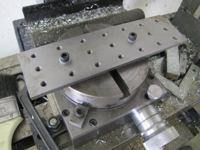
Then it's a simple matter of catching T-nuts fitted to the slots in the rotary table, and the tooling plate easily bolts on to it:
Of course, if needed, the rotary table must be centered to the spindle before bolting on the plate, and one must find a way to center a workpiece to the spindle after clamping down - this requires different methods depending on the workpiece.
:-[ Many of you might have noticed the rust that formed on my once-shiny tooling... With an all-time record wet rainy season here in Namibia, the damp got to all the places on chucks and tooling that I regularly touch in the shop - and then didn't oil when closing up for the day. I think a couple of hours with steel wool or Scotchbrite is in order, followed by a new work ethic of stopping sooner and cleaning and oiling tools used for the session...
Regards, Arnold
Back to tooling for a change - just a minor bit, but useful none-the-less.
As said, I love the tooling plate, and it would be extremely useful if it could be mounted to my rotary table easily.
All of my "small" clamping kit is based around M6 threads, so the holes in the tooling plate are all threaded M6, but so are all the T-nuts I use on my Myford and the rotary table.
This means I can't directly bolt the tooling plate to the rotary table, so I modified a couple of high tensile cap screws of appropriate length by turning of a section of thread long enough to allow it, with a washer, to screw through the tooling plate and then spin freely in the hole once the thread clears:
There's no need to turn it down right to the head; the bit left is just thinner than an ordinary M6 washer.
Then it's a simple matter of catching T-nuts fitted to the slots in the rotary table, and the tooling plate easily bolts on to it:
Of course, if needed, the rotary table must be centered to the spindle before bolting on the plate, and one must find a way to center a workpiece to the spindle after clamping down - this requires different methods depending on the workpiece.
:-[ Many of you might have noticed the rust that formed on my once-shiny tooling... With an all-time record wet rainy season here in Namibia, the damp got to all the places on chucks and tooling that I regularly touch in the shop - and then didn't oil when closing up for the day. I think a couple of hours with steel wool or Scotchbrite is in order, followed by a new work ethic of stopping sooner and cleaning and oiling tools used for the session...
Regards, Arnold
arnoldb
Well-Known Member
- Joined
- Apr 8, 2009
- Messages
- 1,792
- Reaction score
- 12
:big: - I got a nice reminder that this is an old topic when I started this reply; I definitely have not been making enough tools of late.
Well, a bit of tooling for a change. I actually wanted to start on an ER25 collet chuck for my mill. The Cheap 'n Cheerful import I have works well, but after having used the bearing-based closer nut on the lathe's ER chuck, the closer nut on the mill's is a pain to tighten and release. Unfortunately that chuck uses non-standard dimensions, so it's not as easy as just adding a bearing-based closer nut. I've already added some extra collets of the regularly-used sizes to my set, and this morning I set off to start on the new chuck. Bummer... I thought I had some suitable steel to make it from, but I thought wrong. So it'll have to wait till I can buy some steel.
Instead, I started on another collet chuck - an ER11. I've found that the ER25 on my lathe works very well, but at the smaller sizes it's inclined to shrink the collets if they are regularly used at under-sizes. So a couple of months ago I bought a set of ER11 collets which have been sitting idle on the shelf since then.
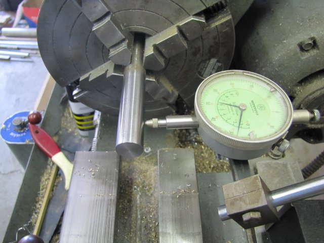
First I clocked up a bit of 16mm silver steel in the 4-jaw. I took my time about it to get it really close - less than 0.0025mm run-out (less than 1/4 deviation between two markings on my best dial indicator). Two years ago this would have taken me 30 minutes; now it takes less than 10... I left quite a bit of stock sticking out of the chuck; that was so that I could check both close to the chuck and further away for run-out:
Then I center drilled the end, turned a 13mm length down to 14mm diameter, and put a threading run-out groove in it:
I set up a 60 degree threading tool:
And started to set up the change gears for a 0.75mm pitch using a bit of paper to set gear clearance:
A very light cut across, and a thread gauge to measure that I had the correct pitch:
I took threading easy; just small increments at a time; 6 passes in total with the final pass at the same infeed as the previous one, and ended up with a nice smooth thread that's a spot-on fit for the ER11 closer nut:
Then I deep-drilled the work through with a good quality sharp 6.5mm drill - I didn't want it to wander too much.:
That was followed by a 7.5mm drill, which is the root depth for ER11 collet chucks. The Myford's top slide swivel graduations are pretty accurate, so I just set it to 8 degrees; that's the standard taper on all ER collets:
Of course I didn't have a small enough boring bar, so I ground one up from some 4mm square HSS blank:
A bit of round 6mm HSS would have worked better, but I don't have any; shopping list amended... The cutting tip was honed on the oilstone to a nice sharp corner, with a very slight radius.
The taper was bored out with light cuts as the workpiece was sticking out so far. When the outside end reached 11mm in diameter I stopped - this is the measurement where the "11" in ER11 comes from:
I love turning silver steel; it's easy to get a nice smooth turned finish.
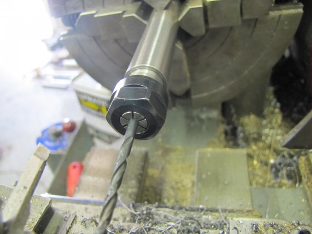
Just had to try it out ;D - a 3mm collet with a 3mm drill bit chucked up:
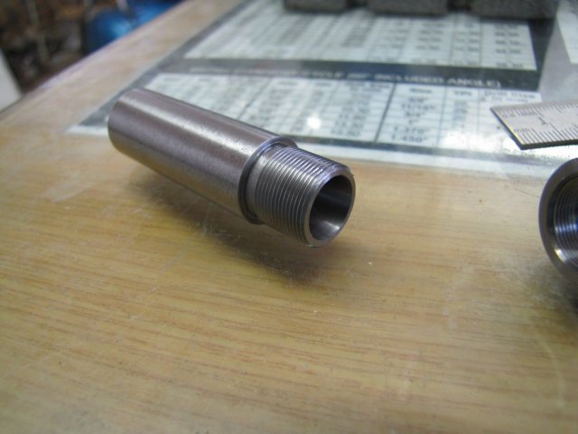
Parted it off, and the final result. Chuck body:
Where the collet fits before it starts to compress:
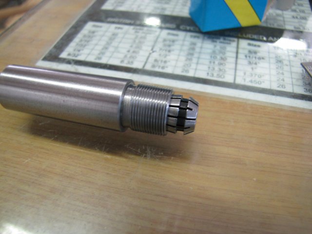
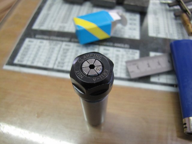
And the 3mm collet compressed with the closer nut to near its smallest diameter:
Of course, the center 7.5mm hole goes right through so that I can extend stock through it:
And a final check on the lathe. I chucked it up in the ER25 collet chuck, as it will see most of its use like this. The 16mm ER25 collet has about 0.01mm run-out; both combined in this setup measured less than 0.015mm run-out; which is fine with me. If I need higher precision, I can always just clock up the ER11 chuck in the 4-jaw chuck:
I didn't add spanner flats to the chuck body; if it's really needed I'll add them later. Of course, this is not the most ideal setup, but will do in more than 80% of the cases where I need to grip small bits on the lathe. It will also work on the mill to grip small cutters or drills. I'll make a dedicated ER11 chuck for the small lathe once I get around to making a stand and mounting it.
Regards, Arnold
Well, a bit of tooling for a change. I actually wanted to start on an ER25 collet chuck for my mill. The Cheap 'n Cheerful import I have works well, but after having used the bearing-based closer nut on the lathe's ER chuck, the closer nut on the mill's is a pain to tighten and release. Unfortunately that chuck uses non-standard dimensions, so it's not as easy as just adding a bearing-based closer nut. I've already added some extra collets of the regularly-used sizes to my set, and this morning I set off to start on the new chuck. Bummer... I thought I had some suitable steel to make it from, but I thought wrong. So it'll have to wait till I can buy some steel.
Instead, I started on another collet chuck - an ER11. I've found that the ER25 on my lathe works very well, but at the smaller sizes it's inclined to shrink the collets if they are regularly used at under-sizes. So a couple of months ago I bought a set of ER11 collets which have been sitting idle on the shelf since then.
First I clocked up a bit of 16mm silver steel in the 4-jaw. I took my time about it to get it really close - less than 0.0025mm run-out (less than 1/4 deviation between two markings on my best dial indicator). Two years ago this would have taken me 30 minutes; now it takes less than 10... I left quite a bit of stock sticking out of the chuck; that was so that I could check both close to the chuck and further away for run-out:
Then I center drilled the end, turned a 13mm length down to 14mm diameter, and put a threading run-out groove in it:
I set up a 60 degree threading tool:
And started to set up the change gears for a 0.75mm pitch using a bit of paper to set gear clearance:
A very light cut across, and a thread gauge to measure that I had the correct pitch:
I took threading easy; just small increments at a time; 6 passes in total with the final pass at the same infeed as the previous one, and ended up with a nice smooth thread that's a spot-on fit for the ER11 closer nut:
Then I deep-drilled the work through with a good quality sharp 6.5mm drill - I didn't want it to wander too much.:
That was followed by a 7.5mm drill, which is the root depth for ER11 collet chucks. The Myford's top slide swivel graduations are pretty accurate, so I just set it to 8 degrees; that's the standard taper on all ER collets:
Of course I didn't have a small enough boring bar, so I ground one up from some 4mm square HSS blank:
A bit of round 6mm HSS would have worked better, but I don't have any; shopping list amended... The cutting tip was honed on the oilstone to a nice sharp corner, with a very slight radius.
The taper was bored out with light cuts as the workpiece was sticking out so far. When the outside end reached 11mm in diameter I stopped - this is the measurement where the "11" in ER11 comes from:
I love turning silver steel; it's easy to get a nice smooth turned finish.
Just had to try it out ;D - a 3mm collet with a 3mm drill bit chucked up:
Parted it off, and the final result. Chuck body:
Where the collet fits before it starts to compress:
And the 3mm collet compressed with the closer nut to near its smallest diameter:
Of course, the center 7.5mm hole goes right through so that I can extend stock through it:
And a final check on the lathe. I chucked it up in the ER25 collet chuck, as it will see most of its use like this. The 16mm ER25 collet has about 0.01mm run-out; both combined in this setup measured less than 0.015mm run-out; which is fine with me. If I need higher precision, I can always just clock up the ER11 chuck in the 4-jaw chuck:
I didn't add spanner flats to the chuck body; if it's really needed I'll add them later. Of course, this is not the most ideal setup, but will do in more than 80% of the cases where I need to grip small bits on the lathe. It will also work on the mill to grip small cutters or drills. I'll make a dedicated ER11 chuck for the small lathe once I get around to making a stand and mounting it.
Regards, Arnold
Hi Arnold,
Glad you posted again on here else I would most likely of not seen it at all
Love all of the idea's and especially that "special" one, the buckle.
You do some tremendous stuff (for want of a better word!) on this site and long may it continue!
Kind regards,
Ron.
Glad you posted again on here else I would most likely of not seen it at all
Love all of the idea's and especially that "special" one, the buckle.
You do some tremendous stuff (for want of a better word!) on this site and long may it continue!
Kind regards,
Ron.
Very nice indeed Arnold.
Your workshop tooling must be getting very close to being finished, then you will have to look for something else to make. ;D
I have to agree with you about the bearing closing nuts, I have been using them now for a few years, and without them on my mill, I wouldn't be able to use ER collets at all. I like the way you can use one hand to get the tooling held in the collet, whereas normally, they would fall out until you could tighten them up with a C spanner.
Keep it up, you will get there in the end.
John
arnoldb
Well-Known Member
- Joined
- Apr 8, 2009
- Messages
- 1,792
- Reaction score
- 12
Thanks Ron; your kind words are much appreciated
John, thank you - My use of the bearing closer nuts is all your fault; I saw those the first time in one of your posts and got hooked.
"Your workshop tooling must be getting very close to being finished, then you will have to look for something else to make." Rof} We both know by now that tooling is never finished! I do have a "something else" in the pipeline; a little engine project that I know you should like. That one have been nagging at me for many months to get built...
Vic, hang in there; they are coming :big: - don't know when yet; you'll just have to watch this space
Well, not too much getting done after work in the evenings at the moment, and this coming weekend I'm going fishing partying with some friends; need to get a bit of the spring-time sunshine ;D
Kind regards, Arnold
John, thank you
- My use of the bearing closer nuts is all your fault; I saw those the first time in one of your posts and got hooked. "Your workshop tooling must be getting very close to being finished, then you will have to look for something else to make." Rof} We both know by now that tooling is never finished! I do have a "something else" in the pipeline; a little engine project that I know you should like. That one have been nagging at me for many months to get built...
Vic, hang in there; they are coming :big: - don't know when yet; you'll just have to watch this space
Well, not too much getting done after work in the evenings at the moment, and this coming weekend I'm going fishing partying with some friends; need to get a bit of the spring-time sunshine ;D
Kind regards, Arnold
arnoldb
Well-Known Member
- Joined
- Apr 8, 2009
- Messages
- 1,792
- Reaction score
- 12
Two weeks gone again
At least the fishing trip the prior weekend was fun; we had beautiful weather, and it was really nice to be out of the town for a change:

Saturday I spent between fixing a neighbour's wife's treadmill (I tried to convince them to junk it so I could get the motor, but that didn't work out) and upgrading my satellite TV installation as my receiver had packed up last week. At least the new receiver have some nice features that will allow me to record the few programs I like to watch; these are usually in shop time, so I'll most likely get more shop from now on and watch the programs later
Sunday dawned, and I didn't feel like precision machining, but wanted to make chips anyway. So I settled on making a vise back stop for my mill; something I've wanted to do for a long time. Material was scrounged from whatever I had around, and I pretty much followed Bogs' build with some minor differences to adapt to my vise and the material I had on hand.
My vise has two 8mm threaded holes on the back of the fixed jaw, so I decided to mount the stop there rather than to drill and tap the vise:
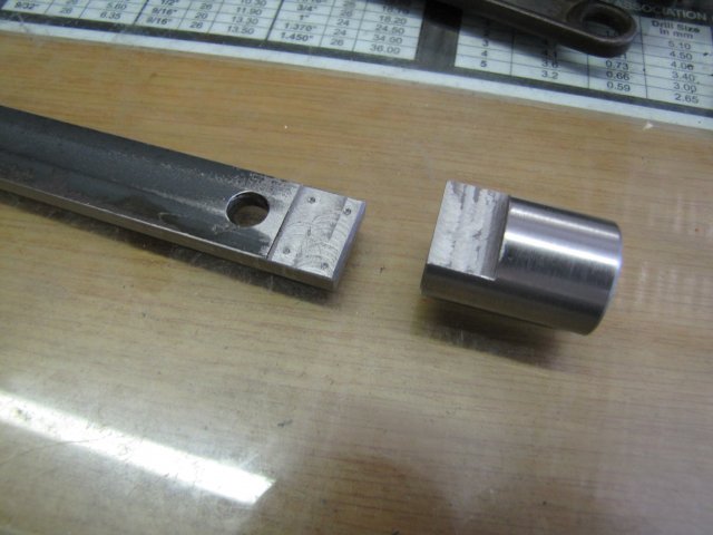
I salvaged a bit of ~25mm hot-rolled round and some bits of 20x5mm hot-rolled flat bar from the odds 'n ends bin and set to work. The round was turned down bit to neaten it up , drilled and then threaded M6 before sawn off to length and the other side just faced to clean it up. I then milled a flat on the other end. A suitable bit of the flat bar was drilled to fit the mounting holes on the vise, and one end flat milled down slightly to get rid of the black scale and the end squared up to mate with the flat on the round bit. Four pop marks with a punch on the milled bit, and I ended up with this:
The clean-up and punch marks on the flat bar was so that I could silver solder the two together leaving a bit of a gap for the solder to wick into. Its easier than welding (well, at least my stick welding :big or fitting screws to join the parts. After silver soldering and a couple of minutes with a wire wheel, I had this:
Fits nicely on the back of the vise:
Then I milled a slot and poked a 12mm hole in another bit of 20x5mm flat bar:
Another bit of HRS round was turned down with a press-fit step on one end for the 12mm hole in the flat bar and drilled and reamed 6mm and the two pressed together after cleaning the mill scale from the flat bar with the wire wheel. I rounded over the ends of the flat bar by eye with a file - just to get a pleasing look, and cut a suitable bit of 6mm silver steel for the stop; this was faced and polished on both ends. All together so far:
And mocked up on the vise:
Had to stop there as some social commitments came up; I still need to make both the locking handles, as well as drill and tap for the adjusting bar locking handle. I can flip the stop over to work from the right-hand-side as well, but I don't think I'll do that too often, as I normally machine on the right-hand side of the vise (or from right to left) so that I don't have to do the blue-chip-dance all the time if I get cranking.
Regards, Arnold
At least the fishing trip the prior weekend was fun; we had beautiful weather, and it was really nice to be out of the town for a change:
Saturday I spent between fixing a neighbour's wife's treadmill (I tried to convince them to junk it so I could get the motor, but that didn't work out) and upgrading my satellite TV installation as my receiver had packed up last week. At least the new receiver have some nice features that will allow me to record the few programs I like to watch; these are usually in shop time, so I'll most likely get more shop from now on and watch the programs later
Sunday dawned, and I didn't feel like precision machining, but wanted to make chips anyway. So I settled on making a vise back stop for my mill; something I've wanted to do for a long time. Material was scrounged from whatever I had around, and I pretty much followed Bogs' build with some minor differences to adapt to my vise and the material I had on hand.
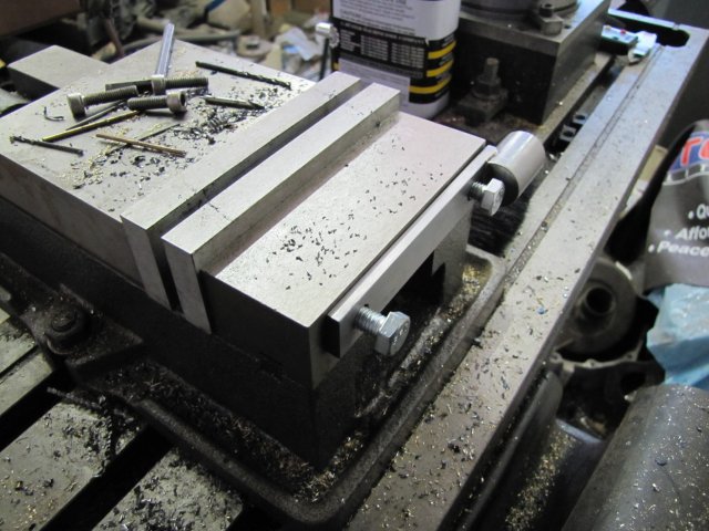
My vise has two 8mm threaded holes on the back of the fixed jaw, so I decided to mount the stop there rather than to drill and tap the vise:
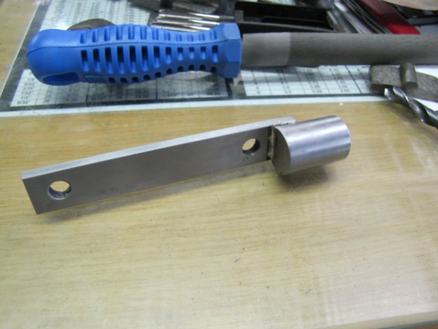
I salvaged a bit of ~25mm hot-rolled round and some bits of 20x5mm hot-rolled flat bar from the odds 'n ends bin and set to work. The round was turned down bit to neaten it up , drilled and then threaded M6 before sawn off to length and the other side just faced to clean it up. I then milled a flat on the other end. A suitable bit of the flat bar was drilled to fit the mounting holes on the vise, and one end flat milled down slightly to get rid of the black scale and the end squared up to mate with the flat on the round bit. Four pop marks with a punch on the milled bit, and I ended up with this:
The clean-up and punch marks on the flat bar was so that I could silver solder the two together leaving a bit of a gap for the solder to wick into. Its easier than welding (well, at least my stick welding :big
or fitting screws to join the parts. After silver soldering and a couple of minutes with a wire wheel, I had this:
Fits nicely on the back of the vise:
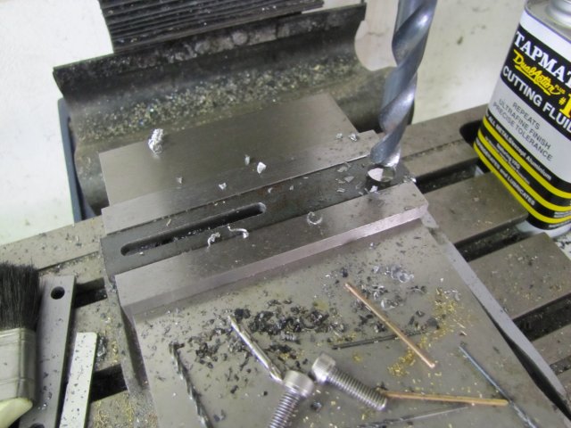
Then I milled a slot and poked a 12mm hole in another bit of 20x5mm flat bar:
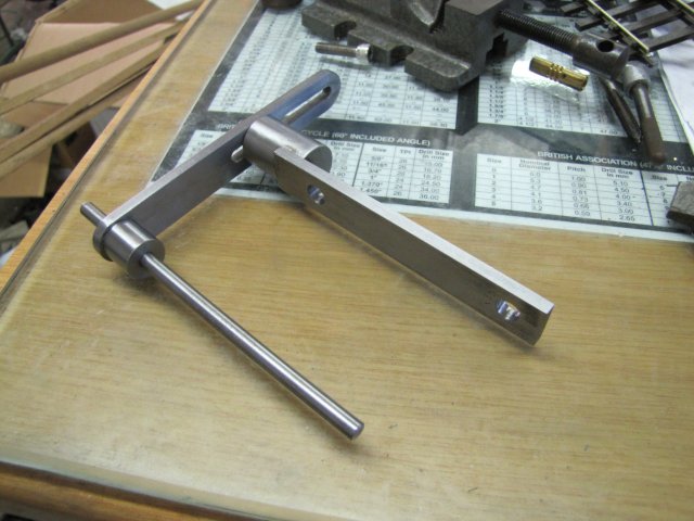
Another bit of HRS round was turned down with a press-fit step on one end for the 12mm hole in the flat bar and drilled and reamed 6mm and the two pressed together after cleaning the mill scale from the flat bar with the wire wheel. I rounded over the ends of the flat bar by eye with a file - just to get a pleasing look, and cut a suitable bit of 6mm silver steel for the stop; this was faced and polished on both ends. All together so far:
And mocked up on the vise:
Had to stop there as some social commitments came up; I still need to make both the locking handles, as well as drill and tap for the adjusting bar locking handle. I can flip the stop over to work from the right-hand-side as well, but I don't think I'll do that too often, as I normally machine on the right-hand side of the vise (or from right to left) so that I don't have to do the blue-chip-dance all the time if I get cranking.
Regards, Arnold
arnoldb
Well-Known Member
- Joined
- Apr 8, 2009
- Messages
- 1,792
- Reaction score
- 12
I sneaked a couple of minutes in the shop after work...
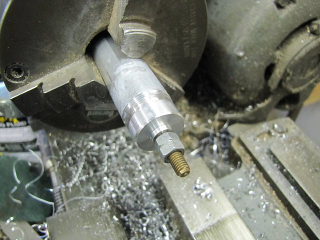
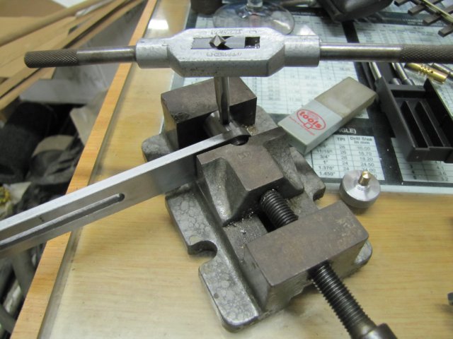
Turned and half-way parted a bit of aluminium bar, drilled and tapped for M5 and screwed a bit of M5 threaded brass into it with a coating of high-strength tread retainer. The two nuts on the brass rod were locked together to allow a bit of torque on the threaded rod to screw it tightly into the aluminium without damaging the threads:
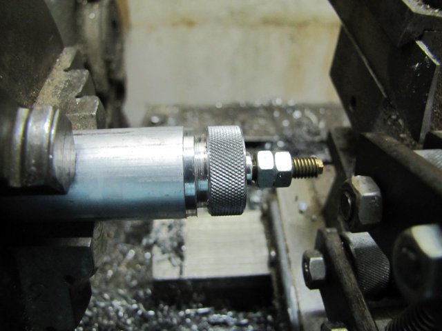
A quick knurl:
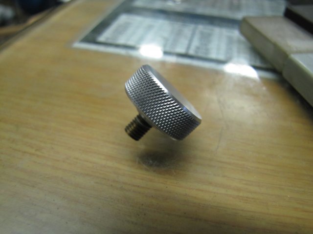
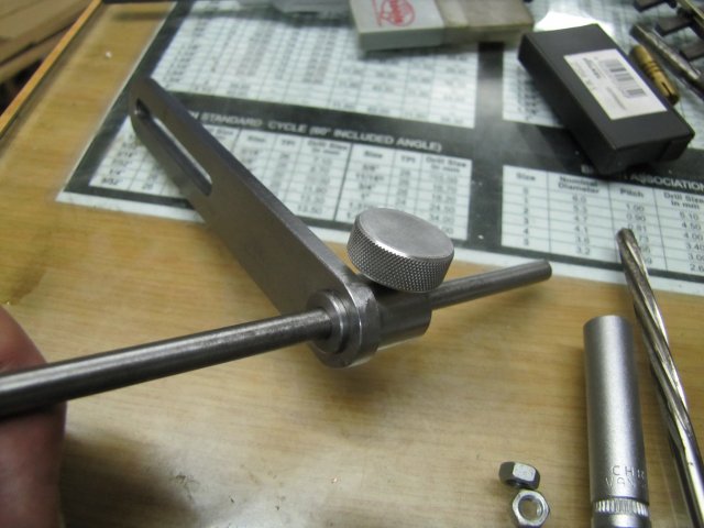
And after parting off, removing the parting pip, a bit of filing and rubbing the parted face on emery , I ended up with this:
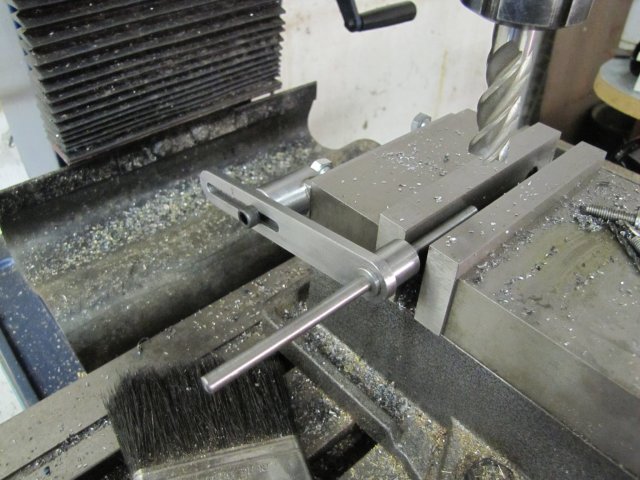
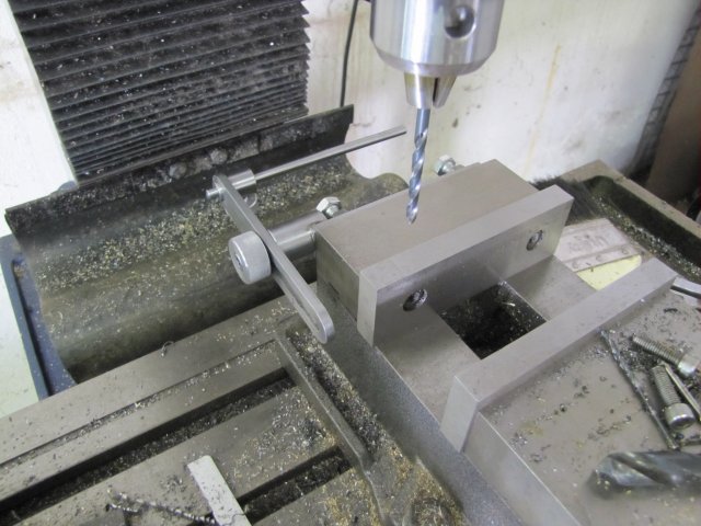
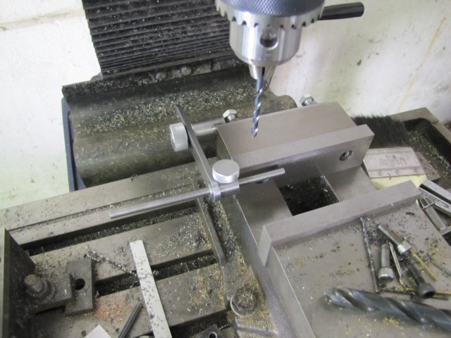
Then I cross-drilled the adjuster end of the stop 4.2mm and passed the 6mm hand-reamer trough the bore to remove the burs on the inside:
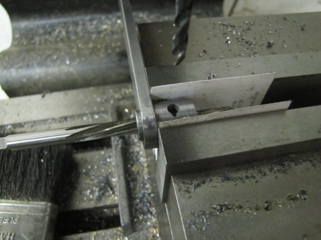
Some hand-tapping:
And the adjuster stop knob was done:
A mad selection of bits 'n bobs for the stop, but I'd like to add that they were actually chosen... The aluminium knob won't rust from sweat on fingers (it gets hot here in Namibia ) and will not need oiling to prevent rust, the brass screw won't harm the silver steel stop arm making it difficult to move, and the brass threaded rod and aluminium knob are pretty much "seized up" on their treads - that's beside the thread retainer I added, so won't easily come unscrewed.
Regards, Arnold
Turned and half-way parted a bit of aluminium bar, drilled and tapped for M5 and screwed a bit of M5 threaded brass into it with a coating of high-strength tread retainer. The two nuts on the brass rod were locked together to allow a bit of torque on the threaded rod to screw it tightly into the aluminium without damaging the threads:
A quick knurl:
And after parting off, removing the parting pip, a bit of filing and rubbing the parted face on emery , I ended up with this:
Then I cross-drilled the adjuster end of the stop 4.2mm and passed the 6mm hand-reamer trough the bore to remove the burs on the inside:
Some hand-tapping:
And the adjuster stop knob was done:
A mad selection of bits 'n bobs for the stop, but I'd like to add that they were actually chosen... The aluminium knob won't rust from sweat on fingers (it gets hot here in Namibia
) and will not need oiling to prevent rust, the brass screw won't harm the silver steel stop arm making it difficult to move, and the brass threaded rod and aluminium knob are pretty much "seized up" on their treads - that's beside the thread retainer I added, so won't easily come unscrewed.Regards, Arnold
arnoldb
Well-Known Member
- Joined
- Apr 8, 2009
- Messages
- 1,792
- Reaction score
- 12
Thanks Kel Those holes can be useful for other things though - like mounting indicators or even angle plates to help set up a tricky casting. I think it's pretty much limited to imagination
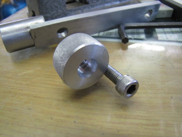
This morning I finished the last bit; a bigger knob for the back; countersunk and tapped M6 to accept a cap screw:
I don't have suitable screws in stock for the back mounting; I want M8 cap screws for that, so I'll buy those when I get a chance to go shopping again. For now, just two M8 bolts holding it on; the bolts are a bit long, but I didn't want to shorten them for a temporary job, so nuts screwed on them to bolt the stop in place. I also added a washer between the rear aluminium knob and the slide; otherwise it will give problems with galling and wear very quickly. Mounted on the vise in out-of-the-way mode:
And in "In-Use" mode:
That didn't take too long to finish today, so I spent the rest of the day giving all my machines a good clean and service. Now its time for an engine build for a change... One Elmer coming up ;D
Regards, Arnold
Those holes can be useful for other things though - like mounting indicators or even angle plates to help set up a tricky casting. I think it's pretty much limited to imagination This morning I finished the last bit; a bigger knob for the back; countersunk and tapped M6 to accept a cap screw:
I don't have suitable screws in stock for the back mounting; I want M8 cap screws for that, so I'll buy those when I get a chance to go shopping again. For now, just two M8 bolts holding it on; the bolts are a bit long, but I didn't want to shorten them for a temporary job, so nuts screwed on them to bolt the stop in place. I also added a washer between the rear aluminium knob and the slide; otherwise it will give problems with galling and wear very quickly. Mounted on the vise in out-of-the-way mode:
And in "In-Use" mode:
That didn't take too long to finish today, so I spent the rest of the day giving all my machines a good clean and service. Now its time for an engine build for a change... One Elmer coming up ;D
Regards, Arnold
Nice one Arnold. :bow: :bow: :bow:
Without mine, I would be lost.
You don't realise just how much you can use such a simple piece of tooling, about 90% of my mill work uses it in one way or another.
John
Without mine, I would be lost.
You don't realise just how much you can use such a simple piece of tooling, about 90% of my mill work uses it in one way or another.
John
Nice one Arnold.
When you have multiple parts to make, a mindset change is needed to move to "batch" production - your stop an invaluable asset in that regards.
Ken
When you have multiple parts to make, a mindset change is needed to move to "batch" production - your stop an invaluable asset in that regards.
Ken
arnoldb
Well-Known Member
- Joined
- Apr 8, 2009
- Messages
- 1,792
- Reaction score
- 12
John, Andrew & Ken, Thanks very much gents
;D The vise stop had it's first bit of use this afternoon after work ; it's really nice to set up for machining on one side of a part then just flipping the part over and doing the opposite side without having to re-set everything
Kind regards, Arnold
;D The vise stop had it's first bit of use this afternoon after work ; it's really nice to set up for machining on one side of a part then just flipping the part over and doing the opposite side without having to re-set everything
Kind regards, Arnold
As I said Arnold, I use mine all the time, not just for making duplicate parts.
Using it in conjunction with parallels, I can take out the piece part being machined for accurate measurement, knowing full well, that when I put it back in position, it will still be in the same position from whence it came.
You will find over time that what you have made will become second nature in it's use, and you will start to get easier to make and more accurately machined parts.
John
arnoldb
Well-Known Member
- Joined
- Apr 8, 2009
- Messages
- 1,792
- Reaction score
- 12
Thank you John. My apologies for the late reply; don't know why I skipped it :-[. You're right; the vise stop now feels like an old friend in the shop; it's REALLY handy
My small lathe has been sitting idle in the shop since I bought it. I've not gotten around to making a suitable stand for it, as I had a bit of material shortage - so yesterday morning I ordered two 6m lengths of 50x50x5 angle iron; these were delivered late today, so now I can get cracking on making the stand.
In the meantime, there were some other issues to attend to. The lathe as I bought it is pretty basic, and one of the worst things is that it did not come with a tailstock drill. A fair warning to would-be hobby lathe buyers: Always make sure you buy a tailstock drill along with a lathe; it's indispensable!
A while ago I bought a small but good quality drill chuck for this purpose, but nobody in Windhoek could supply the suitable "shortened" MT1 arbor needed to fit the lathe's tailstock. Finding bigger tooling is easy here, but small things are rare, as there's no hobby market, so the chuck unfortunately needs a threaded arbor to boot, instead of a Jacobs taper. With our currency currently on a very low point in the international scene, buying one from overseas is a tad expensive for my taste.
So I decided to do what I always do; make my own
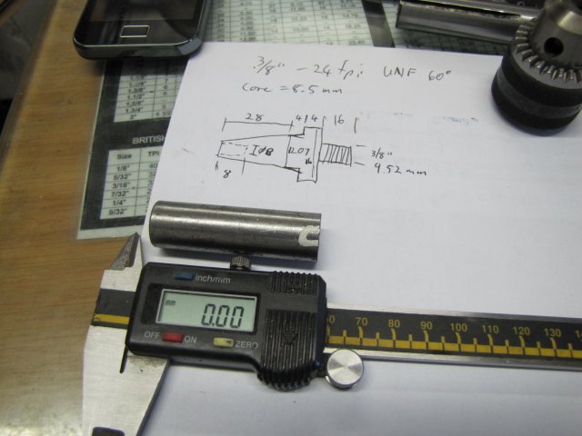
A C-o-C was drawn up, and a bit of 16mm silver steel (drill rod) cut:
To turn the Morse Taper (MT1), I did some calculations for using the Myford's top slide to turn the taper. I do have a taper turning attachment for the Myford, but that's currently already conveniently set for another project:
:-[ "Cross slide" in the image above should be Top Slide; I only noticed it now.
Anyway, to explain a bit of the above:
First off, there are multiple and easier ways to do this, but I felt like taking on a bit of an engineering challenge - that's part of the fun for me. It's also another bit of experience; with this method - if I can pull it off - I can turn pretty much any taper needed without a "reference" piece.
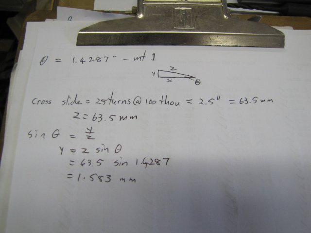
To cut the taper the top slide have to be set at an angle of 1.4287 degrees - not easy to set by eye on the top slide's rotary scale. A sine bar would have been nice to have here, but I must still make one. I have a nice precision protractor, but that's only accurate to 1/100th of a degree - and thus not quite good enough for this purpose.
One way is to use a dial indicator mounted on the top slide measuring against a parallel bar mounted in the lathe to get the "y" value, and to use the top slide's dial to traverse along the hypotenuse of the triangle formed by the taper ("z" in the photo above) for a known distance.
The longer the distance one can measure over, the more accurate you can set the topslide, especially for a very shallow taper like this, so I cranked the Myford's topslide in and out, counting the turns to get a good balance between where its on its maximum "in" (lock up) and "out" (before coming off the feedscrew and still have adequate hold in the dovetails) - this ended up in 25 turns. At 100 thou per full turn, that comes to 2.5" or more conveniently for me 63.5mm.
With a bit of trigonometry, it ended up that the top slide would be set at the correct angle when I could measure 1.583mm travel on the dial indicator over 25 turns of the top slide.
Still a tough call - I only have 0.01mm dial indicators, so I'd have to "read between the lines"
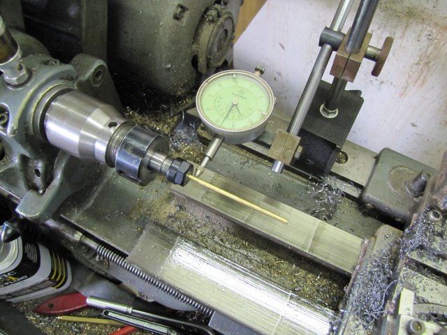
Enough maths, on to the setup. I set the topslide on an angle of about 1.5 degrees on it's scale, and mounted a dial indicator as square as possible to the lathe axis. If you look at the DI's tip, you'll see it has a bit of U-bent plate on it; I don't have different tips for my DIs, and this is a compromise to get a foot for measuring against a round shaft. The shaft I chucked up is nice and straight:
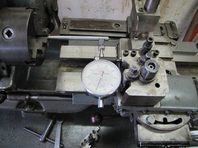
I know my 3-jaw chuck has quite a bit of run-out radially with the outside jaws in it (about 0.1mm!), but is pretty accurate parallel to the lathe ways (less than 0.01mm over 300mm) - but I checked the chucked bar just to make sure on the axial travel. Over the length sticking out and cranking on the apron, the DI barely moved, so that's still OK, and I don't need to turn down a bit of bar to get a more accurate test piece.
Then I locked the carriage down, and started by setting the DI to zero at with the topslide at maximum-less-a-bit infeed and on a zero reading on the topslide dial, with backlash taken up in the direction of it's feed:
After cranking the topslide out 25 turns, I got a reading of 1.32mm:
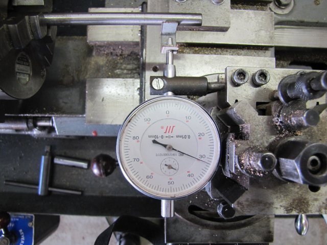
(The small mm dial on this CCC DI runs the wrong way :big
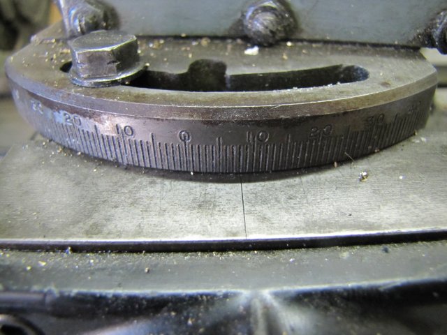
Too shallow a taper then, so I needed more offset on the topslide. I needed ~1.58mm, but the topslide pivots, so it's no good to just set it over to read 1.58mm - it has to be set to less than that. So I split the difference between the earlier 1.32 and the 1.58 - and I lightly tapped the crosslide over a bit more to get 1.45 on the dial. I then repeated this a couple of times, with the different readings - splitting the difference each time. I ended up with this on the dial:
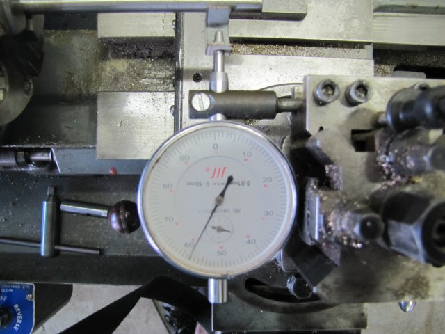
A fuzzy photo with the focus in the wrong place :wall: - a click on the above photo should show more detail - you want to look at the DI face. Earlier on, I mentioned that I'd have to "read between the lines" - and this is it - a reading of 1.58something - between what I would think 1.580mm and 1.585mm, and what I'd guesstimate at 1.583mm. That's as close as I can do in my home shop - even a loud f@rt would disrupt it.
The next step is actually turning the taper. First things first, and the toolbit has to be set spot-on on height:
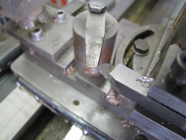
My crappy-looking very-newby-project height gauge still does the job adequately
A bit of silver steel (drill rod) turned down to 12.1mm diameter on 32mm length, and marked at 28mm for the end of the taper:
Taper turned part way down:
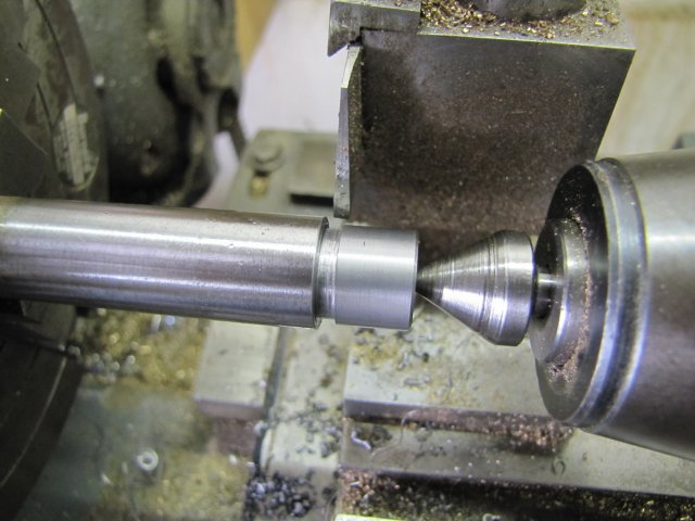
Time for a final check; some engineer's blue smeared on the taper:
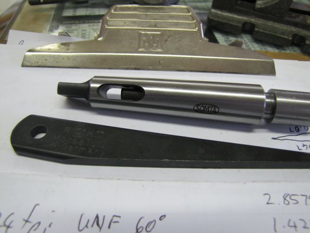
I have a good quality MT2 to MT1 reducer - so I used that to check the taper; slid it on and turned it a bit:
The result - the taper is ever so slightly tighter at the big end, but that's OK by me:
A final finishing cut:
And the end counter bored 8mm deep:
I wanted as much taper as possible on this arbor, and the counter bore is needed to add an additional bit of travel on the small lathe's tailstock; every bit helps...
To turn the thread on the arbor, I need to mount it in the MT2 to MT1 reducer sleeve, and mount that lot in the Myford's head stock. There is a problem though; if I tap the arbor-in-making into the sleeve, I'd have a bummer of a time to get it out because of it's shortened taper. A bit of rummaging around my scrap bin produced an old 1/8" drill with a MT1 shank:
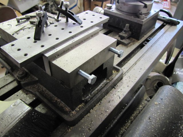
The shank on drills normally is not hardened, so I gave it a test with a file to make sure, and the file cut it, so I clamped it in the vise and hacksawed it off at an appropriate length:
A quick trip to the bench grinder to clean up the sawn end, and I had a nice insert:
With the insert lightly tapped down into the sleeve, followed by the arbor-in-making, and I can use a Morse key to remove both:
While I had the top slide set up on the lathe, I turned two more taper blanks from silver steel:
The original arbor was then fit in the lathe headstock, and tidied up a bit:
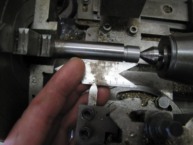
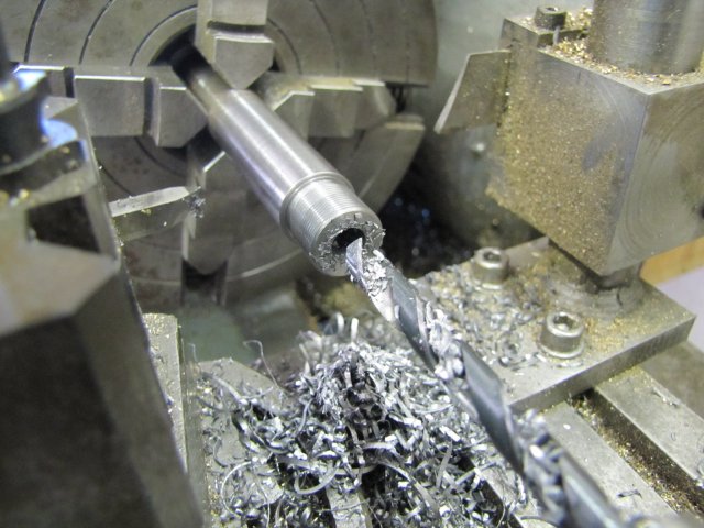
Next, turned down to fit the register in the chuck, a thread run-out groove added, and the section to be threaded turned down to 9.52mm (3/8"):
A quick test with a very light threading groove to check the thread pitch:
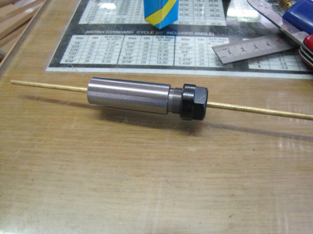
The thread turned for a good, but slightly tight fit in the drill chuck; it's better to have it a bit on the tight side for a chuck arbor:
Chuck screws on pretty much perfectly - I'm a happy chappy ;D:
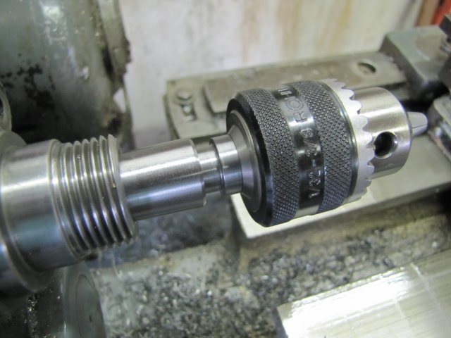
Finally, in it's place on the small lathe:
Then I had a thought... That's dangerous, but what the heck; I gathered some bits 'n bobs and one of the other blanks I'd turned up earlier:
The MT1 blank was drilled and bored for a push fit for the bearings - leaving the drill bit cone in the end of the hole intact:
I decided not to use the 5mm silver steel rod shown in the photo before the last one; instead I used some 6mm silver steel rod and turned a 60 degree taper on the end:
Then turned it down to 5mm for a tight push fit for the bearings:
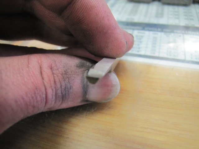
The bit was then parted off - leaving a 2mm long 6mm step at the end. I then mounted it in a 5mm collet, and faced off the parted end, and with a big center drill put a cone on the end:
A quick brass spacer and a PTFE ring turned for a press fit in the body and a running fit on the shaft, and this is the lot together - ready for assembly:
The PTFE ring is just to keep swarf and dirt out of the works. The step left at the end of the shaft is so that I can use the shaft to pull out the bearings for servicing.
All assembled up with a good dollop of high-pressure grease on the bearing ball, and I have a small running center - I think it turned out quite well ;D:
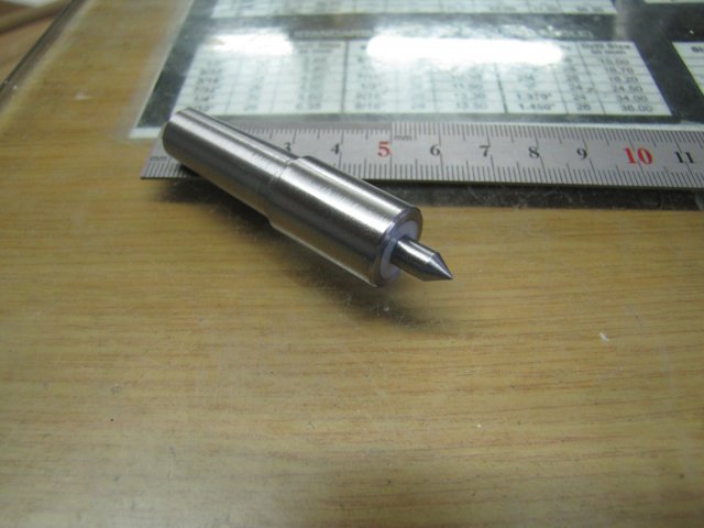
Of course, it's a light duty running center, but I've needed one for a long time.
Couldn't resist a quick test; it works a treat ;D:
Wow - this was a mammoth post; I hope I didn't bore anybody to death!
Regards, Arnold
My small lathe has been sitting idle in the shop since I bought it. I've not gotten around to making a suitable stand for it, as I had a bit of material shortage - so yesterday morning I ordered two 6m lengths of 50x50x5 angle iron; these were delivered late today, so now I can get cracking on making the stand.
In the meantime, there were some other issues to attend to. The lathe as I bought it is pretty basic, and one of the worst things is that it did not come with a tailstock drill. A fair warning to would-be hobby lathe buyers: Always make sure you buy a tailstock drill along with a lathe; it's indispensable!
A while ago I bought a small but good quality drill chuck for this purpose, but nobody in Windhoek could supply the suitable "shortened" MT1 arbor needed to fit the lathe's tailstock. Finding bigger tooling is easy here, but small things are rare, as there's no hobby market, so the chuck unfortunately needs a threaded arbor to boot, instead of a Jacobs taper. With our currency currently on a very low point in the international scene, buying one from overseas is a tad expensive for my taste.
So I decided to do what I always do; make my own
A C-o-C was drawn up, and a bit of 16mm silver steel (drill rod) cut:
To turn the Morse Taper (MT1), I did some calculations for using the Myford's top slide to turn the taper. I do have a taper turning attachment for the Myford, but that's currently already conveniently set for another project:
:-[ "Cross slide" in the image above should be Top Slide; I only noticed it now.
Anyway, to explain a bit of the above:
First off, there are multiple and easier ways to do this, but I felt like taking on a bit of an engineering challenge - that's part of the fun for me. It's also another bit of experience; with this method - if I can pull it off - I can turn pretty much any taper needed without a "reference" piece.
To cut the taper the top slide have to be set at an angle of 1.4287 degrees - not easy to set by eye on the top slide's rotary scale. A sine bar would have been nice to have here, but I must still make one. I have a nice precision protractor, but that's only accurate to 1/100th of a degree - and thus not quite good enough for this purpose.
One way is to use a dial indicator mounted on the top slide measuring against a parallel bar mounted in the lathe to get the "y" value, and to use the top slide's dial to traverse along the hypotenuse of the triangle formed by the taper ("z" in the photo above) for a known distance.
The longer the distance one can measure over, the more accurate you can set the topslide, especially for a very shallow taper like this, so I cranked the Myford's topslide in and out, counting the turns to get a good balance between where its on its maximum "in" (lock up) and "out" (before coming off the feedscrew and still have adequate hold in the dovetails) - this ended up in 25 turns. At 100 thou per full turn, that comes to 2.5" or more conveniently for me 63.5mm.
With a bit of trigonometry, it ended up that the top slide would be set at the correct angle when I could measure 1.583mm travel on the dial indicator over 25 turns of the top slide.
Still a tough call - I only have 0.01mm dial indicators, so I'd have to "read between the lines"
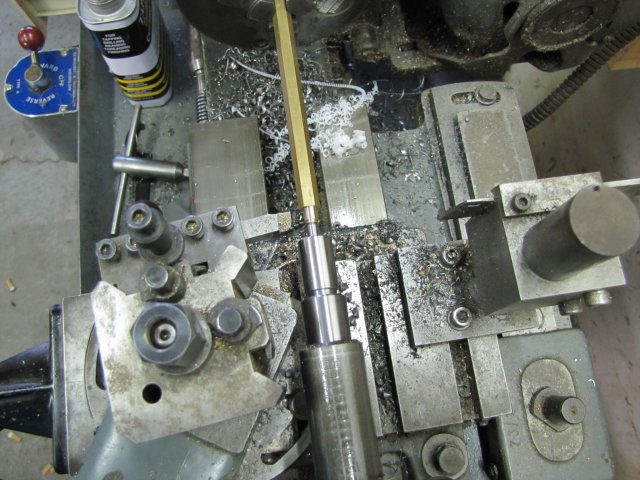
Enough maths, on to the setup. I set the topslide on an angle of about 1.5 degrees on it's scale, and mounted a dial indicator as square as possible to the lathe axis. If you look at the DI's tip, you'll see it has a bit of U-bent plate on it; I don't have different tips for my DIs, and this is a compromise to get a foot for measuring against a round shaft. The shaft I chucked up is nice and straight:
I know my 3-jaw chuck has quite a bit of run-out radially with the outside jaws in it (about 0.1mm!), but is pretty accurate parallel to the lathe ways (less than 0.01mm over 300mm) - but I checked the chucked bar just to make sure on the axial travel. Over the length sticking out and cranking on the apron, the DI barely moved, so that's still OK, and I don't need to turn down a bit of bar to get a more accurate test piece.
Then I locked the carriage down, and started by setting the DI to zero at with the topslide at maximum-less-a-bit infeed and on a zero reading on the topslide dial, with backlash taken up in the direction of it's feed:
After cranking the topslide out 25 turns, I got a reading of 1.32mm:
(The small mm dial on this CCC DI runs the wrong way :big
Too shallow a taper then, so I needed more offset on the topslide. I needed ~1.58mm, but the topslide pivots, so it's no good to just set it over to read 1.58mm - it has to be set to less than that. So I split the difference between the earlier 1.32 and the 1.58 - and I lightly tapped the crosslide over a bit more to get 1.45 on the dial. I then repeated this a couple of times, with the different readings - splitting the difference each time. I ended up with this on the dial:
A fuzzy photo with the focus in the wrong place :wall: - a click on the above photo should show more detail - you want to look at the DI face. Earlier on, I mentioned that I'd have to "read between the lines" - and this is it - a reading of 1.58something - between what I would think 1.580mm and 1.585mm, and what I'd guesstimate at 1.583mm. That's as close as I can do in my home shop - even a loud f@rt would disrupt it.
The next step is actually turning the taper. First things first, and the toolbit has to be set spot-on on height:
My crappy-looking very-newby-project height gauge still does the job adequately
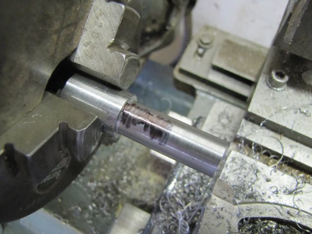
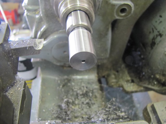
A bit of silver steel (drill rod) turned down to 12.1mm diameter on 32mm length, and marked at 28mm for the end of the taper:
Taper turned part way down:
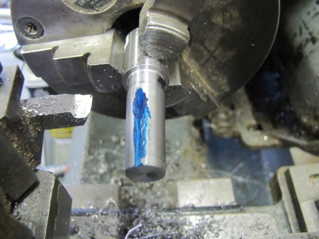
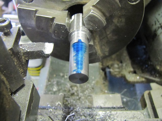
Time for a final check; some engineer's blue smeared on the taper:
I have a good quality MT2 to MT1 reducer - so I used that to check the taper; slid it on and turned it a bit:
The result - the taper is ever so slightly tighter at the big end, but that's OK by me:
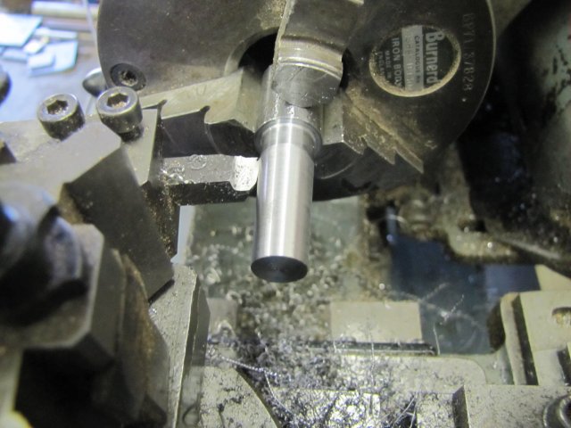
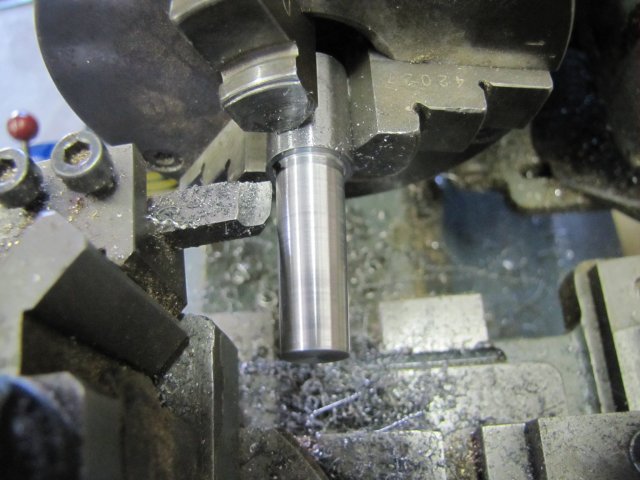
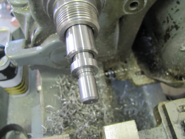
A final finishing cut:
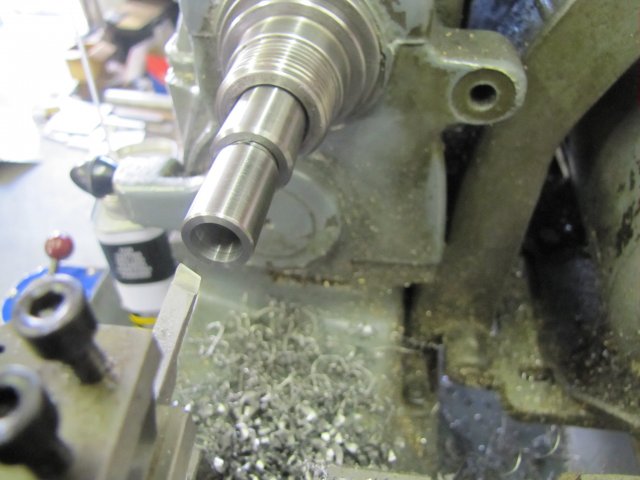
And the end counter bored 8mm deep:
I wanted as much taper as possible on this arbor, and the counter bore is needed to add an additional bit of travel on the small lathe's tailstock; every bit helps...
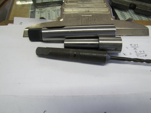
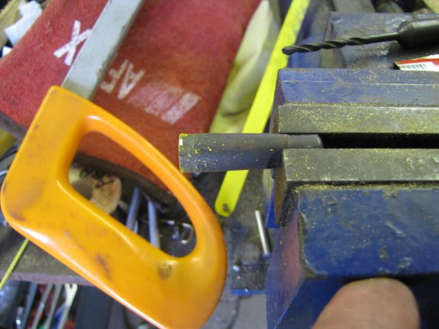
To turn the thread on the arbor, I need to mount it in the MT2 to MT1 reducer sleeve, and mount that lot in the Myford's head stock. There is a problem though; if I tap the arbor-in-making into the sleeve, I'd have a bummer of a time to get it out because of it's shortened taper. A bit of rummaging around my scrap bin produced an old 1/8" drill with a MT1 shank:
The shank on drills normally is not hardened, so I gave it a test with a file to make sure, and the file cut it, so I clamped it in the vise and hacksawed it off at an appropriate length:
A quick trip to the bench grinder to clean up the sawn end, and I had a nice insert:
With the insert lightly tapped down into the sleeve, followed by the arbor-in-making, and I can use a Morse key to remove both:
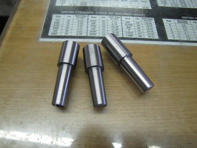
While I had the top slide set up on the lathe, I turned two more taper blanks from silver steel:
The original arbor was then fit in the lathe headstock, and tidied up a bit:
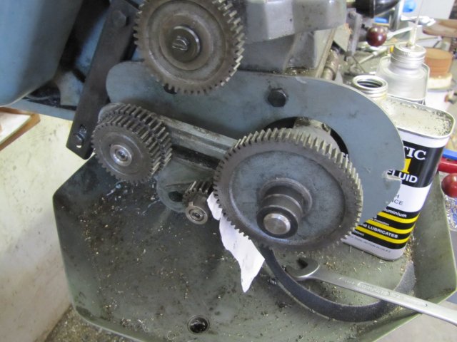
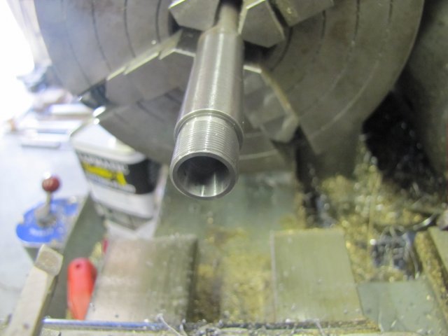
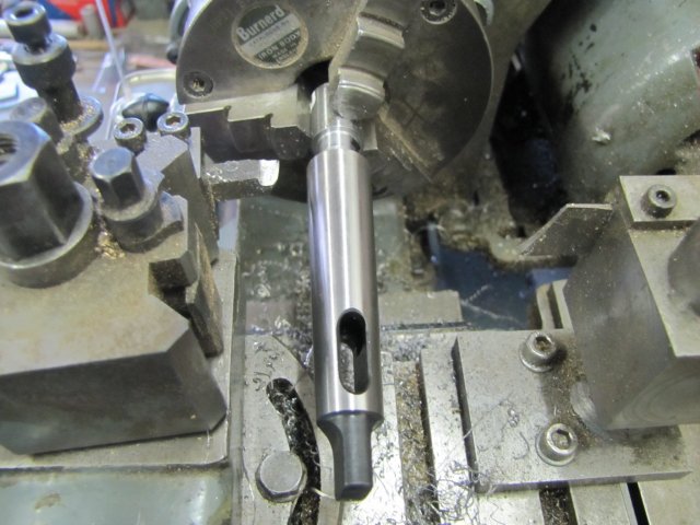
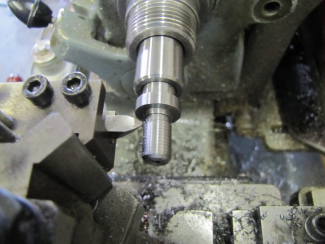
Next, turned down to fit the register in the chuck, a thread run-out groove added, and the section to be threaded turned down to 9.52mm (3/8"):
A quick test with a very light threading groove to check the thread pitch:
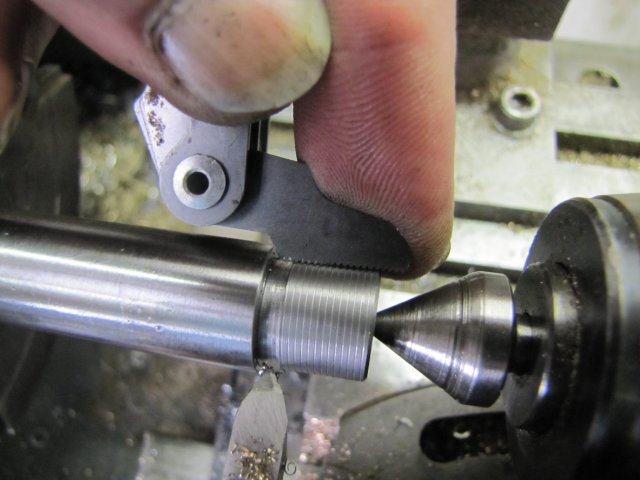
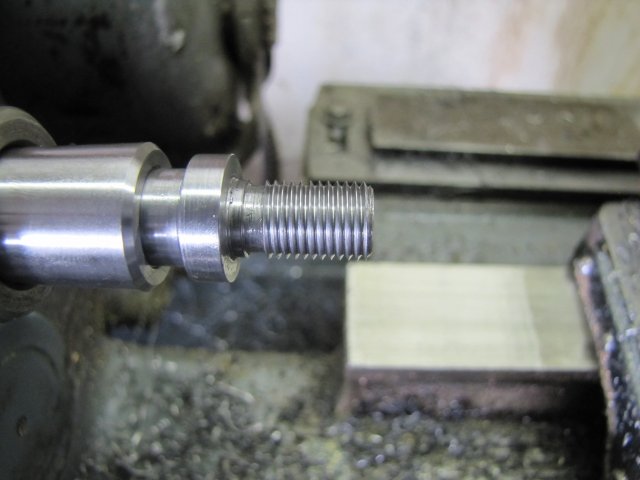
The thread turned for a good, but slightly tight fit in the drill chuck; it's better to have it a bit on the tight side for a chuck arbor:
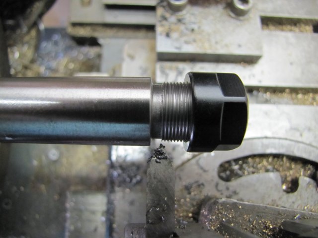
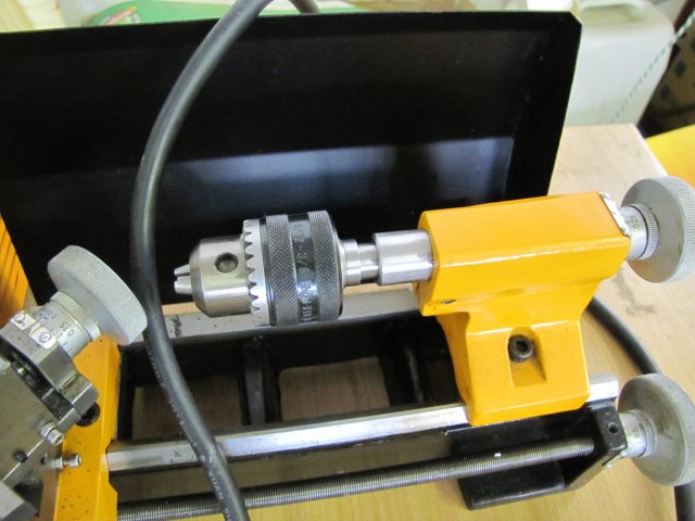
Chuck screws on pretty much perfectly - I'm a happy chappy ;D:
Finally, in it's place on the small lathe:
Then I had a thought... That's dangerous, but what the heck; I gathered some bits 'n bobs and one of the other blanks I'd turned up earlier:
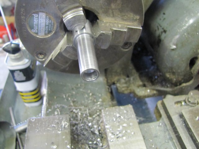
The MT1 blank was drilled and bored for a push fit for the bearings - leaving the drill bit cone in the end of the hole intact:
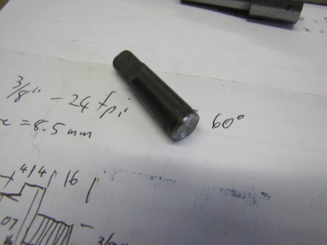
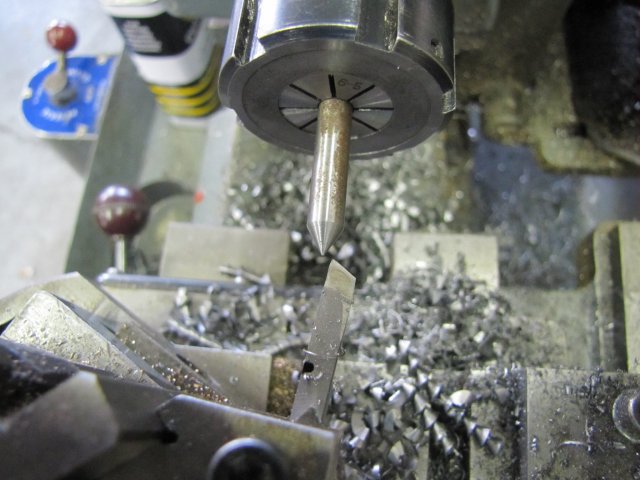
I decided not to use the 5mm silver steel rod shown in the photo before the last one; instead I used some 6mm silver steel rod and turned a 60 degree taper on the end:
Then turned it down to 5mm for a tight push fit for the bearings:
The bit was then parted off - leaving a 2mm long 6mm step at the end. I then mounted it in a 5mm collet, and faced off the parted end, and with a big center drill put a cone on the end:
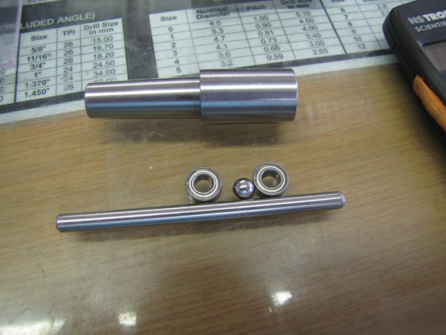
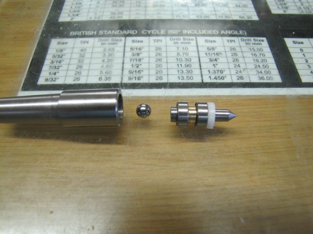
A quick brass spacer and a PTFE ring turned for a press fit in the body and a running fit on the shaft, and this is the lot together - ready for assembly:
The PTFE ring is just to keep swarf and dirt out of the works. The step left at the end of the shaft is so that I can use the shaft to pull out the bearings for servicing.
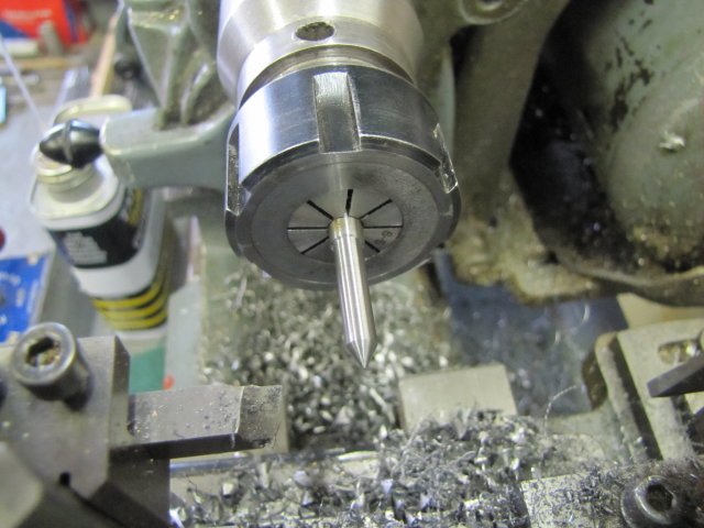
All assembled up with a good dollop of high-pressure grease on the bearing ball, and I have a small running center - I think it turned out quite well ;D:
Of course, it's a light duty running center, but I've needed one for a long time.
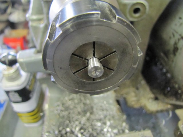
Couldn't resist a quick test; it works a treat ;D:
Wow - this was a mammoth post; I hope I didn't bore anybody to death!
Regards, Arnold
Lockstocknbarrel
Well-Known Member
- Joined
- Oct 19, 2010
- Messages
- 71
- Reaction score
- 18
Arnold,
I class you as a Mentor, thank you for the massive amount of time you take to photo document the items that you build, and write the plans so that dirty rotten plagiarists like myself can build a item without the pitfalls, in today's electronic world, thanks must go to people like you, please don't stop this thread.
Kindest Regards
Beagles
arnoldb
Well-Known Member
- Joined
- Apr 8, 2009
- Messages
- 1,792
- Reaction score
- 12
Thank you Beagles. I don't know about mentoring, but it's my way of repaying the generosity of many others who have freely and selflessly helped me come along in the hobby.
;D Dave, I know you do! - I'll keep them coming Thm:
Kind regards, Arnold
;D Dave, I know you do! - I'll keep them coming Thm:
Kind regards, Arnold