arnoldb
Well-Known Member
- Joined
- Apr 8, 2009
- Messages
- 1,792
- Reaction score
- 12
Marv once suggested that one must keep a list of all the little tools that would make life easier while machining. I took that advice, and have a growing list (it'll never end!) and will peck away at it as and when I have time - or foresee a need for specific items for an upcoming build. It's easier to have needed tools before any engine build; that can save a lot of time and frustration, as well as keep a build on track.
I have also been surprised quite a couple of times when I received PMs or emails with queries about the small tooling bits I have thrown into my build logs thus far, so I decided to create a single thread dedicated to making all my small bits and bobs from said list - queries and suggestions are as always welcome.
A lot of the things I'll be making are available commercially - or have been designed and made already by others; I doubt very much that anything new will surface here, but there will on occasion be my own twist as I adapt ideas to suit my own needs and machinery - or simply use what I have on hand to make a useful - but safe to use - item. I do enjoy making my own tools, and I think I have learned as much, if not more, about machining from making tools as I have from building engines.
Some of the items that will get done in this thread include, but is not limited to the following - in no particular order or sequence of completion:
Adjustable parallels
Small sine bars
Angle plate for the mill
Edge finders
Vise stops
Toolmaker's clamps - a diverse selection
Knurling tool - my current one is just horrible!
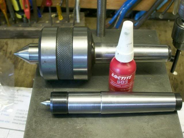
Pump center
Tooling plate for the mill
Collet blocks for my ER collets
Cylindrical squares
Spinning post and tools for the lathe
Lathe chuck back-stop
Cross drilling jigs
...and more...
More complex items - like a Tool Grinder will get their own threads when I get around to those.
To kick off, a lifelong friend recently asked me if I could help him make some ball knobs for some furniture he's restoring. I don't normally turn wood on my lathe, but for some people and jobs I'd do it, so cue a ball turner.
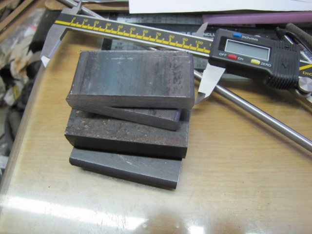
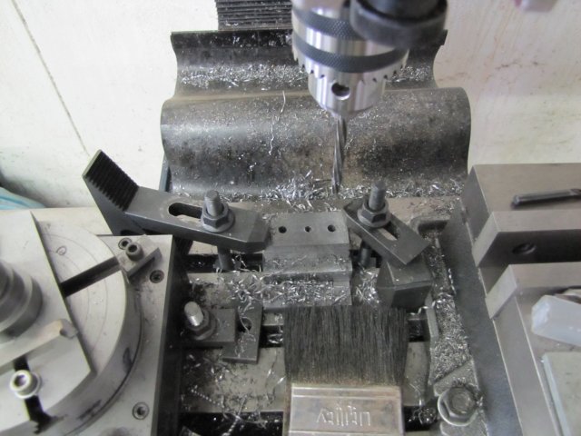
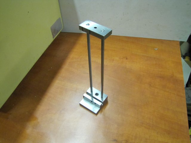
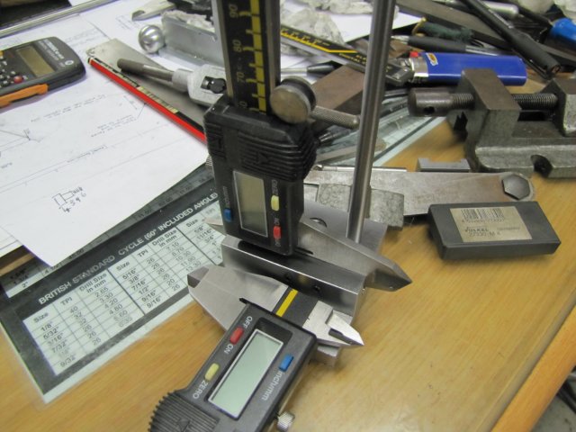
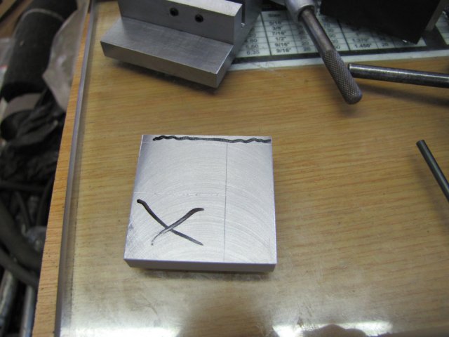
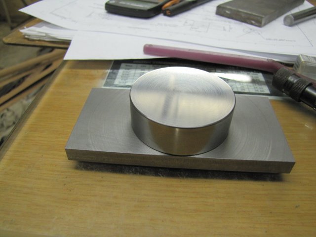
I cobbled this one together based on Steve Bedair's design, and sized for my Myford ML7; there have been a lot of them built, so not too much build details. It's based on a length of 50mm x 10mm hot-rolled flat bar and a short bit of 55mm diameter cast iron that I turned down:
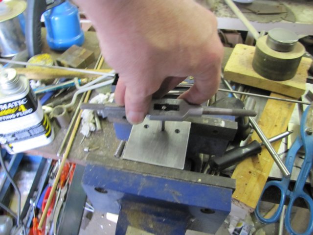
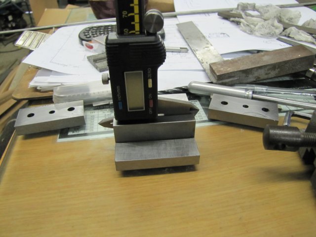
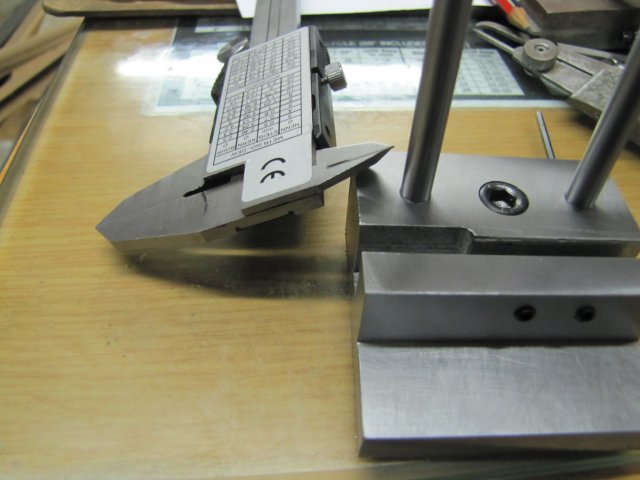
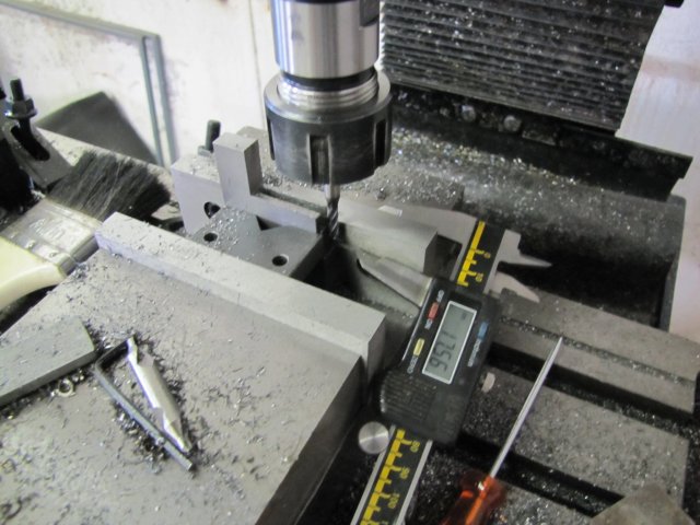
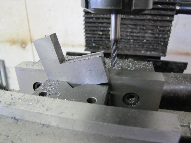
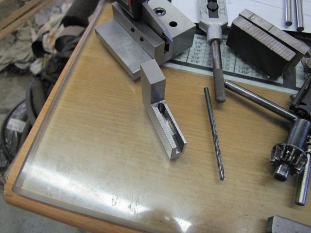
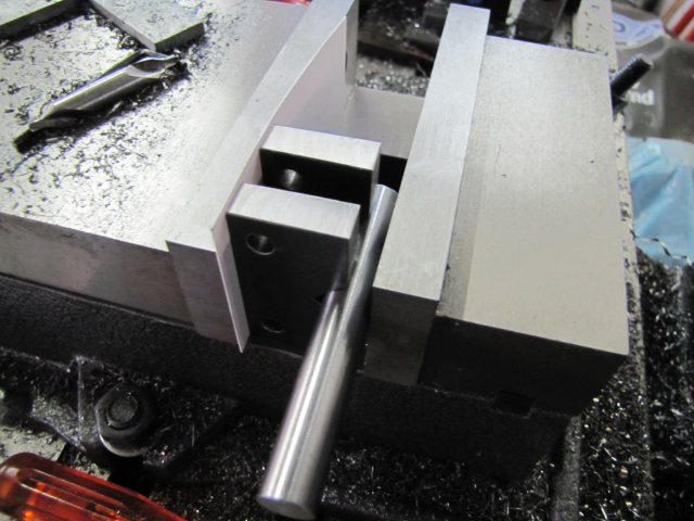
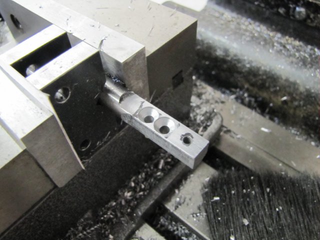
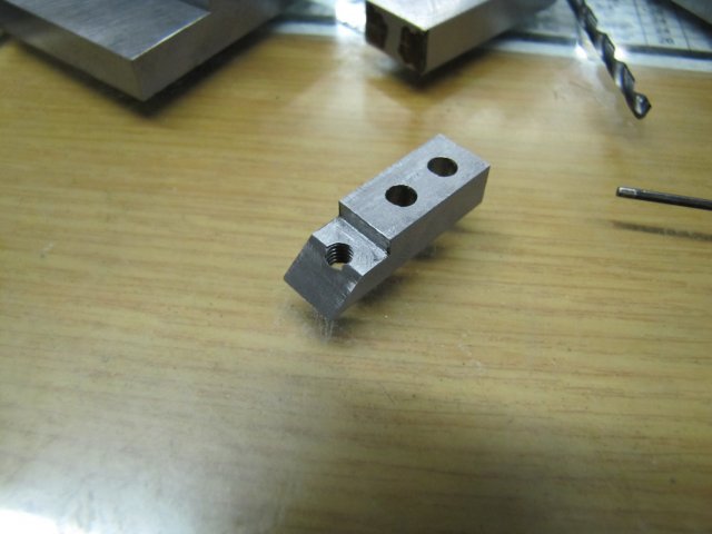
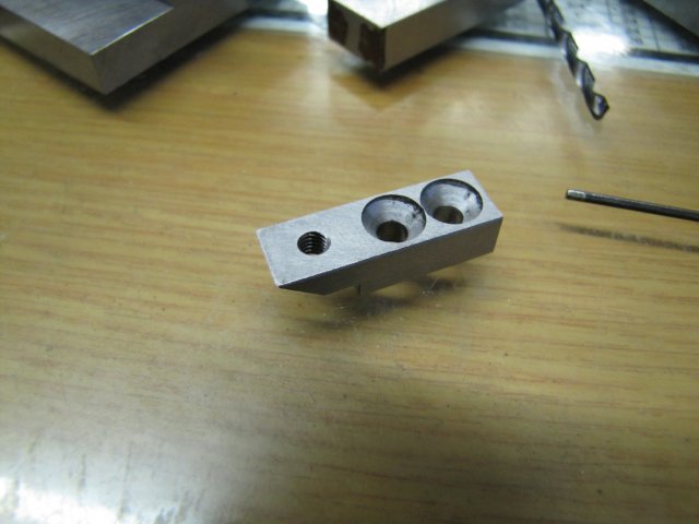
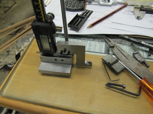
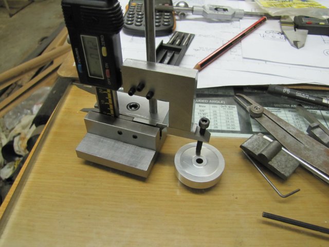
I have quite a bit of round 4mm HSS blanks that I use regularly, so the toolbit for this would, naturally for me, be of the same instead of the inserts normally preferred - so the tool carrier was adapted to take the HSS with two grub screws (set screws) to lock it in place. I didn't work from the plans; I just bodged along on this one and made parts to "gut feel". All the parts done:
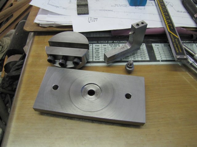
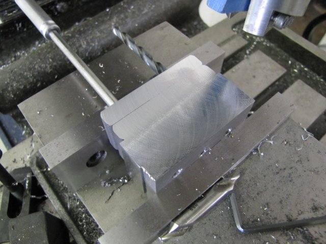
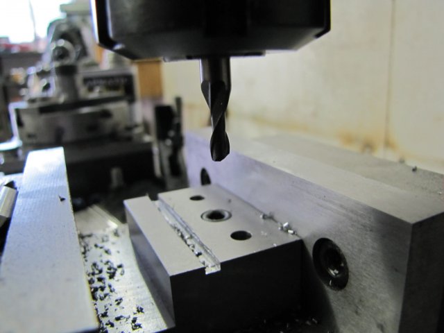
The head rides on the protrusion on the base, and has a boss that locates very closely in the hole bored in the base. The toolpost is also just some of the same flat bar as the base; I milled the slot in the head 9mm wide, so that I could fly-cut the icky black coating off the HRS for a slightly neater appearance. The screw I turned up from silver steel (drill rod) as it needs to be tough; I didn't harden and temper it; in it's untreated state silver steel is quite tough, so that is ideal for this job. The correct shoulder length on the screw was obtained through trial-and-error fits while I was making it - I simply turned the length down by minute amounts each time, and when the base plate and head screwed on and the base was just slightly tight to turn between the head and screw shoulder I stopped; the slight stiffnes will wear out quickly. This may sound a bit crude, but it does work. The toolbit hole is dead on center with the lathe spindle - I usually grind the round HSS toolbits I use like this down half-way at the tip, as the curve of the bottom part then gives adequate clearance in most cases.
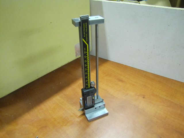
All assembled and on the lathe:
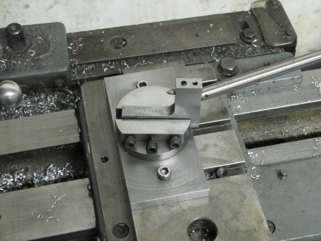
I used some grease instead of oil to lubricate the moving parts.
Definitely not the prettiest tool I've made - I didn't file and sand down all the machining marks like I do of late... but does it work?:
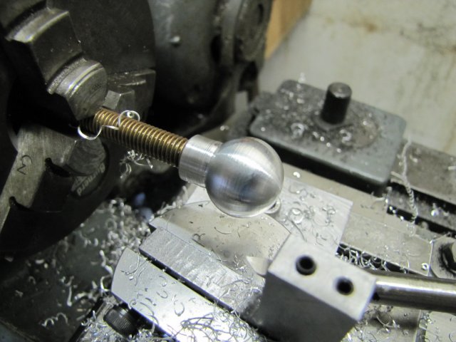
Yes, even though I was too lazy to turn up a proper mandrel from steel; the brass threaded rod deflected like mad while turning, but still it only took about 5 minutes to turn that up.
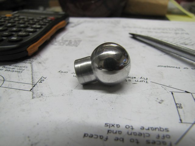
And a bit of emery later:
Regards, Arnold
I have also been surprised quite a couple of times when I received PMs or emails with queries about the small tooling bits I have thrown into my build logs thus far, so I decided to create a single thread dedicated to making all my small bits and bobs from said list - queries and suggestions are as always welcome.
A lot of the things I'll be making are available commercially - or have been designed and made already by others; I doubt very much that anything new will surface here, but there will on occasion be my own twist as I adapt ideas to suit my own needs and machinery - or simply use what I have on hand to make a useful - but safe to use - item. I do enjoy making my own tools, and I think I have learned as much, if not more, about machining from making tools as I have from building engines.
Some of the items that will get done in this thread include, but is not limited to the following - in no particular order or sequence of completion:
Adjustable parallels
Small sine bars
Angle plate for the mill
Edge finders
Vise stops
Toolmaker's clamps - a diverse selection
Knurling tool - my current one is just horrible!
Pump center
Tooling plate for the mill
Collet blocks for my ER collets
Cylindrical squares
Spinning post and tools for the lathe
Lathe chuck back-stop
Cross drilling jigs
...and more...
More complex items - like a Tool Grinder will get their own threads when I get around to those.
To kick off, a lifelong friend recently asked me if I could help him make some ball knobs for some furniture he's restoring. I don't normally turn wood on my lathe, but for some people and jobs I'd do it, so cue a ball turner.
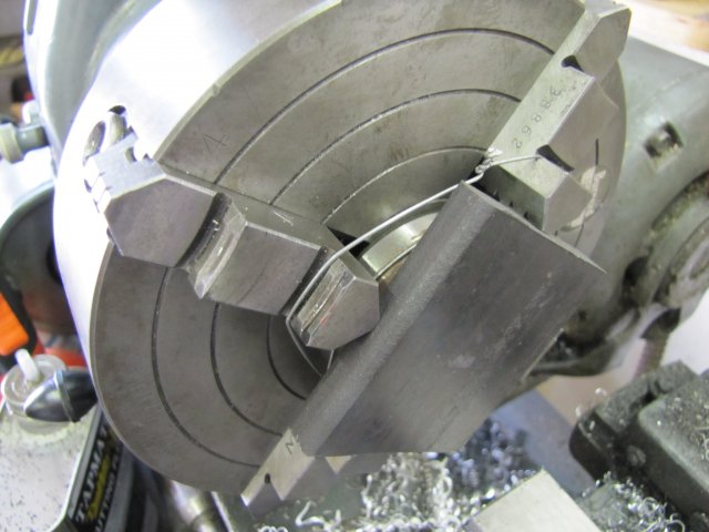
I cobbled this one together based on Steve Bedair's design, and sized for my Myford ML7; there have been a lot of them built, so not too much build details. It's based on a length of 50mm x 10mm hot-rolled flat bar and a short bit of 55mm diameter cast iron that I turned down:
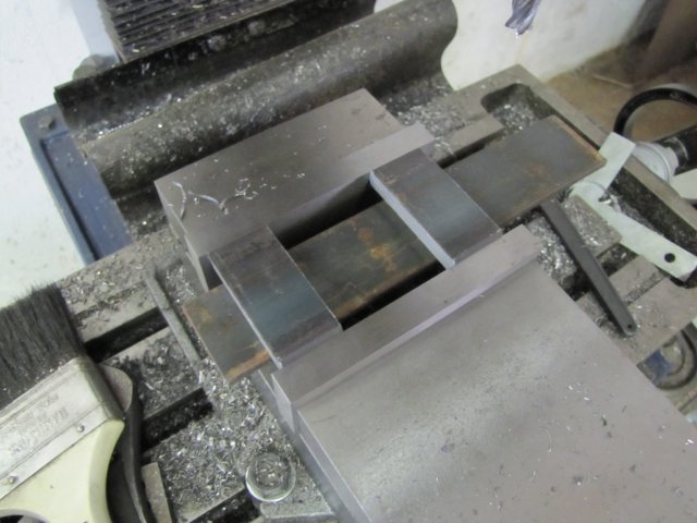
I have quite a bit of round 4mm HSS blanks that I use regularly, so the toolbit for this would, naturally for me, be of the same instead of the inserts normally preferred - so the tool carrier was adapted to take the HSS with two grub screws (set screws) to lock it in place. I didn't work from the plans; I just bodged along on this one and made parts to "gut feel". All the parts done:
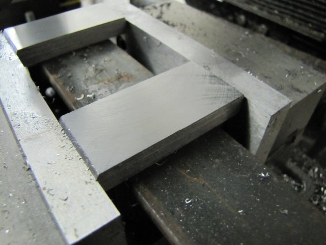
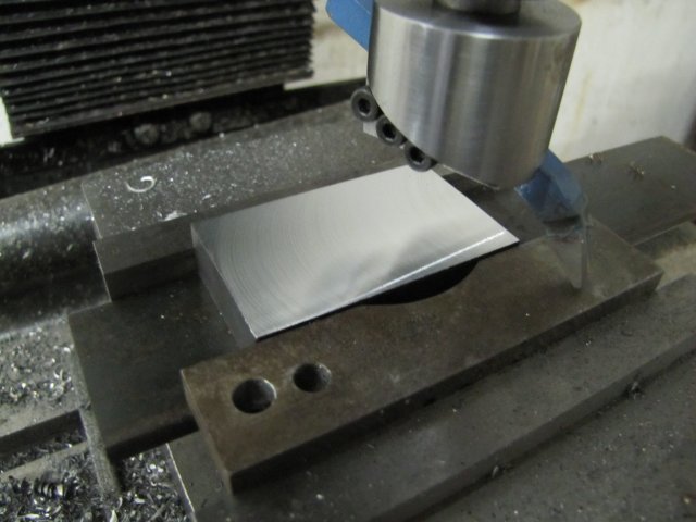
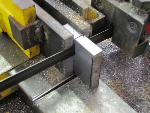
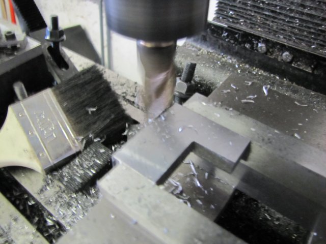
The head rides on the protrusion on the base, and has a boss that locates very closely in the hole bored in the base. The toolpost is also just some of the same flat bar as the base; I milled the slot in the head 9mm wide, so that I could fly-cut the icky black coating off the HRS for a slightly neater appearance. The screw I turned up from silver steel (drill rod) as it needs to be tough; I didn't harden and temper it; in it's untreated state silver steel is quite tough, so that is ideal for this job. The correct shoulder length on the screw was obtained through trial-and-error fits while I was making it - I simply turned the length down by minute amounts each time, and when the base plate and head screwed on and the base was just slightly tight to turn between the head and screw shoulder I stopped; the slight stiffnes will wear out quickly. This may sound a bit crude, but it does work. The toolbit hole is dead on center with the lathe spindle - I usually grind the round HSS toolbits I use like this down half-way at the tip, as the curve of the bottom part then gives adequate clearance in most cases.
All assembled and on the lathe:
I used some grease instead of oil to lubricate the moving parts.
Definitely not the prettiest tool I've made - I didn't file and sand down all the machining marks like I do of late... but does it work?:
Yes, even though I was too lazy to turn up a proper mandrel from steel; the brass threaded rod deflected like mad while turning, but still it only took about 5 minutes to turn that up.
And a bit of emery later:
Regards, Arnold
")