Arnold's tooling odds 'n ends

Home Model Engine Machinist Forum

Help Support Home Model Engine Machinist Forum:

This site may earn a commission from merchant affiliate links, including eBay, Amazon, and others.
I finished the height gauge today ;D - and used it for the first time as well.

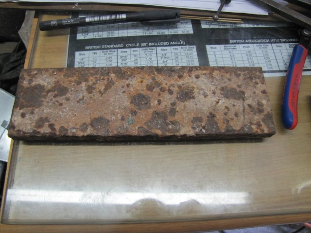
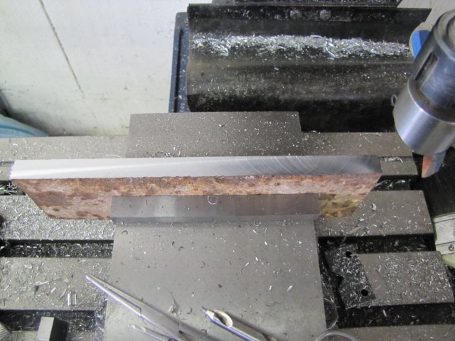
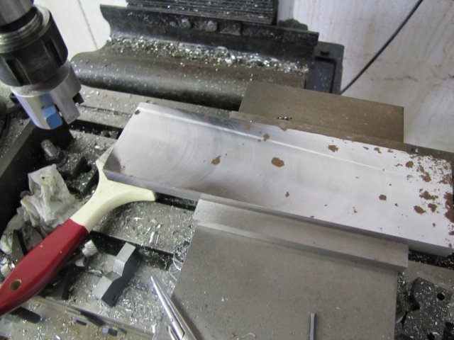
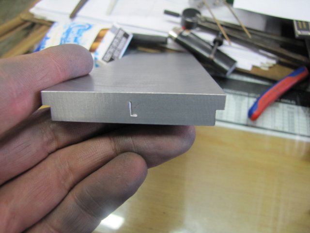
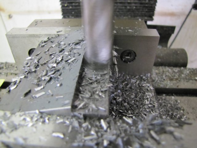
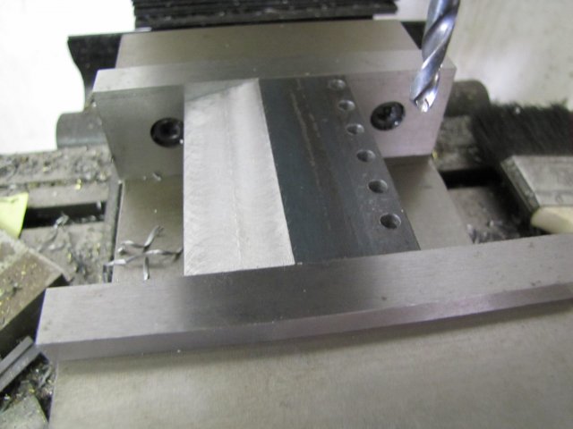
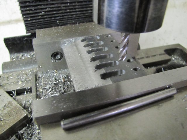
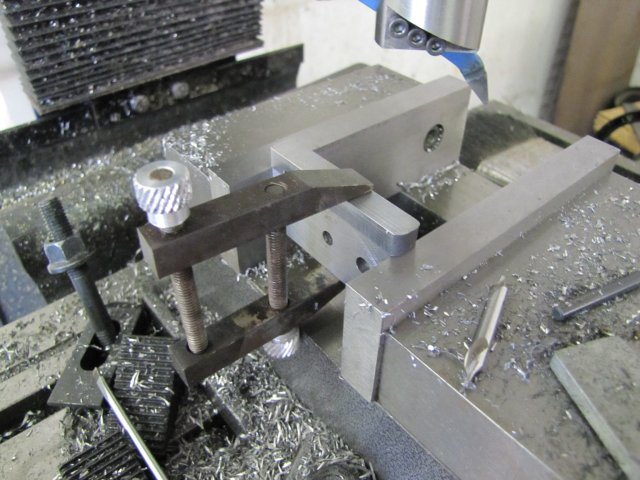
First up - the top caliper retainer. Another bit of HRS sawn off, and lightly cleaned up, then clamped to the top guide for drilling for a couple of M3 cap screws:
normal_IMG_1859.JPG


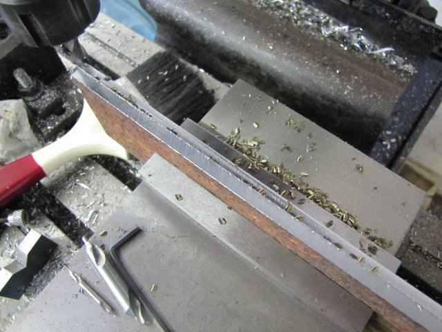
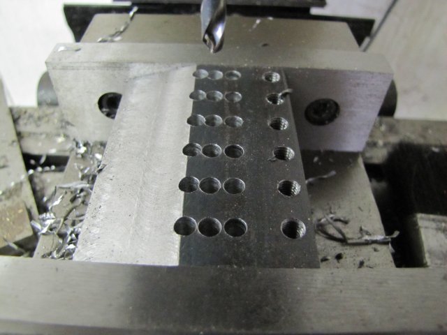
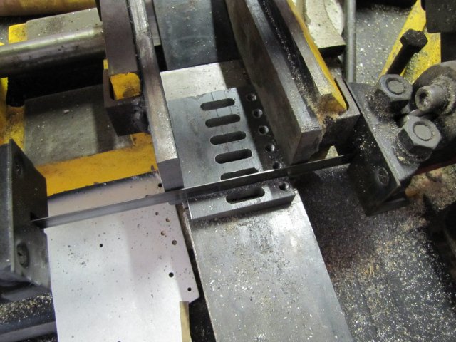
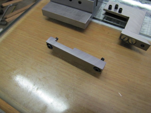
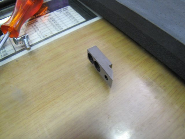
I just drilled the holes 2.5mm for threading, then separated the lot and finished the retainer on it's own by enlarging the holes to 3mm for clearance, and counter bored with a 5mm end mill to recess the screw caps for a neater look. A cutout slightly wider than the caliper shank was milled into it - but not as deep as the caliper shank is thick. Then overall dimensions were milled to size, and the result:
normal_IMG_1860.JPG


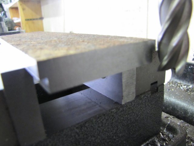
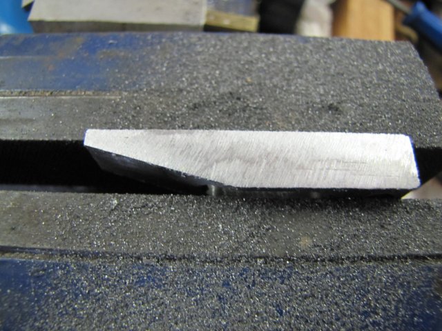
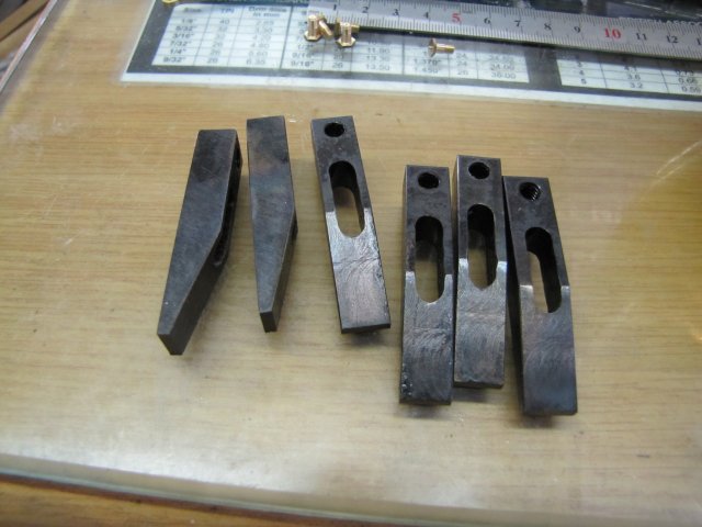
The scriber tip was then taken outside - together with a can of oil, and heated red hot and dunked in the oil to cool down. This left it nice and black... So I cleaned off some of the black with emery, and gently heated it again only on the thick side till the cleaned area changed to a light yellow-orange colour close to the scriber tip. I then left it to cool down; that should be enough tempering. Then I cleaned it all up again, and lightly stoned the bottom of the piece on the sharpening stone, followed by quite a bit of stoning on the top angle to get it nice and sharp. It's pretty hard so takes a bit of effort to sharpen up:
normal_IMG_1861.JPG

Trying to get rid of the black left in the screw recesses seemed too daunting, so I left it ::)

Now for final assembly :)
A flat reference surface is needed; a surface plate would be ideal, but I don't have one. I do have the glass sheet that I use instead, so I thoroughly cleaned an area of it, as well as the underside of the base of the stand and the bottom of the scribing tip.
It's important that the caliper shank stands as close as possible to vertical - but if it's out of vertical by, say, 0.1mm over the 120mm range my caliper has, it would make the princely error of being out by about 0.00005mm over the measuring range... - way more accurate than can usually be measured in a home shop. So I just used a square against the protruding caliper tips to set it vertical in the stand:
normal_IMG_1862.JPG


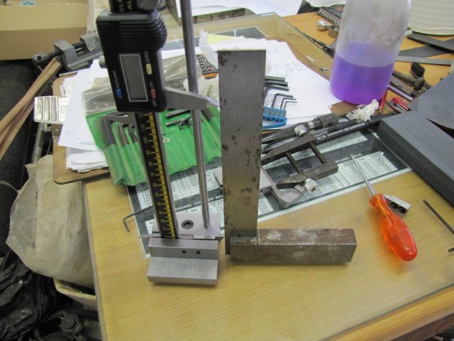
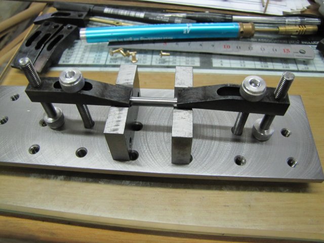
Setting the scribing bit level and flat with respect to the base is more important. I did this by holding the scribing arm with the foot flat on the glass, and raising the caliper's top leg into the machined slot. Then a light tighten of the middle screw, followed by the outer ones, and that's that:
normal_IMG_1863.JPG


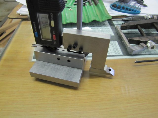
To make double sure, I measured the shank of a broken 1.4mm drill both at the tip of the scriber foot:
normal_IMG_1865.JPG


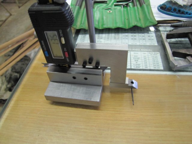
As well as at the back:
normal_IMG_1867.JPG


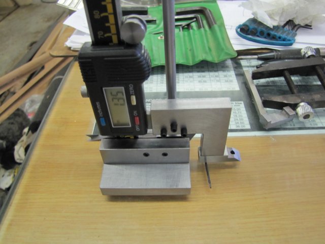
Finally; good to go; I'll get some shorter set screws to replace the ones holding the arm when I get to the nuts and bolts supplier next time:
normal_IMG_1869.JPG


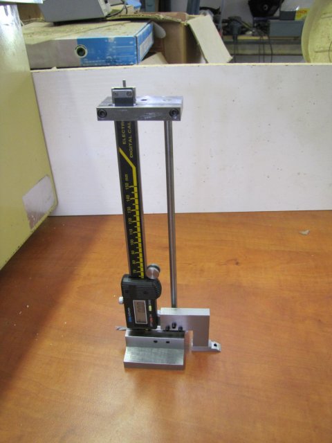
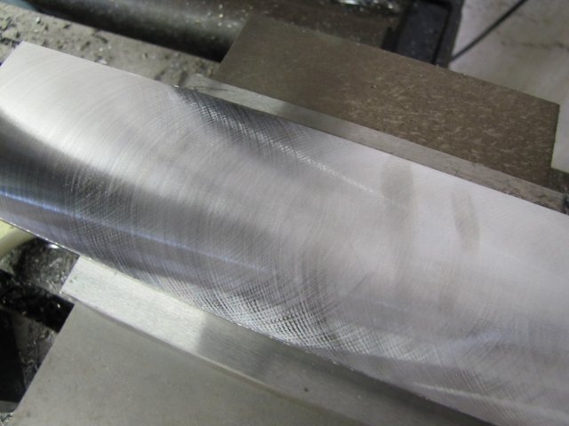
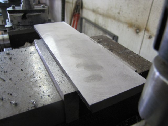
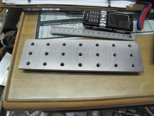
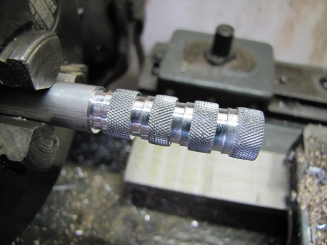
In use for the first time on my next project:
normal_IMG_1874.JPG

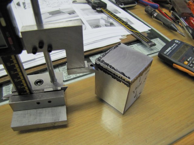
MUCH easier than jiggling the workpiece to scribe some lines on it with a normal caliper ;D - I think I'm going to like this tool!

Regards, Arnold
 
Great work, Arnold, and a very nice construction presentation for future readers.

Yes, they are handy tools. When I started out I couldn't grasp their utility but, after impulse buying one at a sale, I began to really appreciate their usefulness. Now I own three of them and use all of them regularly.
 
Arnold,

Another great project comes to a successful conclusion. :bow: :bow:

Best Regards
Bob
 
Marv & Bob - many thanks!

For those wondering where the images are, it appears that my hosting service's server is down, and as a result all the images are unavailable at the moment.
I hope they get it back online soon. Server's back up

Regards, Arnold
 
Well done, Arnold. Your usual instructive thread and good pics, and a useful tool for your shop.
 
Dean, Doc - Much apologies for a very late Thank You! - Don't know how I missed your posts :-[


My shop time has not been as much as I'd hoped for the last month, so not much was done...
On Saturday I managed to find some time to do a bit of recycling to sort out the mess I had around my mill and to gain some storage space. A discarded printer stand on casters from work, a sink cut-out from a counter top, some salvaged pine shelving installed in it, a couple of old 3 1/2" floppy storage containers to sort out and organise all my end mills and a pine block drilled full of some holes to hold cutters that are in frequent use yielded this lot after a bit of work:
normal_IMG_2207.JPG

normal_IMG_2209.JPG


I have a couple of days off, and actually wanted to carry on with my experimental locomotive today, but there's going to be a lot of small bits that will need holding down for the next machining operations, so I decided to detour a little and make a tooling plate that will make life easier. Besides, I also wanted to give the milling cutters I received from Richon Tools a go.

I dug a well-weathered bit of 65 x 12mm mild steel flat bar from my scrap:
normal_IMG_2211.JPG

Did say "well weathered ::) - I have used bits of this in the past, and while it machines fairly easily, it is a right bummer to try and get any kind of even half-decent finish on.

There is no way I was going to introduce new toolbits to that lot; there is all kinds of crud embedded in that rust, so I first brought out the flycutter with a right-hand turning tungsten tipped lathe tool in it, and started by cleaning off both long edges of the workpiece:
normal_IMG_2212.JPG


Then started facing off the rust and crud from one face; nothing very accurate here; I merely aligned things by eye and had at it with a couple of 0.5mm deep passes. This is after the first pass:
normal_IMG_2213.JPG

There was some funny crud amongst that rust... Left a constant shower of sparks going. And HOT chips; I was doing a silly dance in between brushing those off :big: But then, I was cranking along at about 6mm per second; I've found my mill has no complaints when getting pushed along a bit.

Then I tried the 12mm carbide mill I got... Decided I'd be bold and go for it. With the cleaned workpiece face against the fixed jaw, and the mill running at its max 1200rpm, I took out a 5mm wide x 4mm deep edge cut in one pass. Started with a slowish feed rate, and increased it; that carbide mill just took away metal happily at up to 6mm per second ;D:
normal_IMG_2214.JPG

Left some nice golden-coloured and equally sized chips... I think it could be pushed even harder... I LIKE it ;D

With the milling spindle left locked in the same setting, I removed the workpiece, de-burred the slight burr raised (visible in the previous photo), flipped the piece end over end, and milled the other edge off as well. The carbide mill's cutting flutes are a bit short, which is a pity, so I swapped it for one of the new 16mm HSS 4-flute end mills, slowed the mill down - it is HSS after all - and faced the ends. I took two photos, and neither was in focus where they needed to be ::) - so a bit of a fuzzy pic:
normal_IMG_2215.JPG

That end mill left a really nice finish ;D

With the workpiece clamped on the steps and tapped down on top of the mill vise, I started facing off the top with the flycutter. After a couple of passes with the tungsten cutter:
normal_IMG_2217.JPG


And a finishing pass with the HSS flycutting tool - I left some finger prints on there "testing" the surface:
normal_IMG_2218.JPG

There's still some cutting marks visible - as you'll see more clearly in further photos. If this was aluminium or brass, I'd be looking at my ugly mug on that surface; like I said earlier in the post, this steel is horrible to get a good finish on.

When I removed the workpiece from the vise, I was careful to mark the left side, and after de-burring, I stamped an "L" on the left side:
normal_IMG_2220.JPG

This is for a reason. Because the plate was just clamped on the top of the vise - where it's normal usage position will be, the movable vise jaw will have lifted a tiny amount (no matter how good quality your vise is!). It was machined square to the spindle on top with this slight lift in play. If one rotates the plate, and mount it in the vise with the original "left side" on the right, the error from lifting is in fact doubled, and the tool plate will be higher by double the vise movable jaw lift at the side of the movable jaw. There are other factors that also come into play, such as how hard the tool plate is clamped, how much wear occurs on the vise and so on, but IMHO the lift in the vise jaw is the main player. It will never be 100% accurate on re-clamping, but for 98% of my work it will go back accurately enough if oriented correctly. For the other 2% requiring the optimum accuracy, there are other ways to address the issue. Incidentally, I measured the difference on the front and back sides, and my vise lifts by about 0.02mm at that width.

Then I clamped the workpiece back in the mill vise, and drilled a grid of 5mm holes in it. Didn't bother with spotting the holes first; I just chucked the 5mm drill bit in the collet chuck with about 15mm of it sticking out to allow for some clearance but to keep it "stiff" and poked the holes:
normal_IMG_2221.JPG

I don't know how many will be convenient in future; that's a lesson of learning on the job. For now, I just used convenient spacing - 30mm apart in X (10 turns of my mill's x handle) and 20mm apart in Y. I set the mill dials to zero on the top left hole - that was my reference and co-ordinate drilled from there, counting turns.

The drilling was followed by a good dose of counter-sink in each hole:
normal_IMG_2222.JPG


Then on to a new process for me... I have not tapped under power on my mill yet. ::) - well, I haven't even had it for a year! :big: It has a "tapping" function, which cuts power when the quill indicator reaches maximum depth, and prevents forward rotation to be switched on, but does allow reverse to be turned on. This has actually annoyed me in the past, as on many occasions I would have liked to adjust the quill indicator to use it as a stop to repetitively drill down to an exact depth without the spindle stopping. Today, some of that frustration was alleviated ;D - I'll re-wire the mill later on to allow me to switch the feature on and off though - but for today it was just great ;D

Before embarking on this power threading learning curve, I sat down and thought it through. I have not seen any detailed write-ups on the process, but then, neither have I searched for any.
I decided to treat it exactly like I do hand-tapping. Go through the entire set of taps, cleaning the tap and squirting some cutting fluid on it before each hole. For the machine part, mill at the slowest (80 RPM), and a light one-finger down-feed on the quill handles; that should let me feel when the tap "takes", with the
down-feed kept on while the tap is doing it's business. When the machine stops, lighten the one-finger feed, to allow the quill to pull up, but not at full strength.

I was concerned about the second and third taps not "taking" properly and cross threading - that didn't happen; they picked up the previous tap's thread just fine - I could feel when that happened quite distinctly on the feeding "finger". Needless to say, things worked a treat and saved me a lot of wrist-twisting ;D :
[ame]http://www.youtube.com/watch?v=uAkQUfk9op0[/ame]
There was one brown-pant moment though... When I changed from the first to the second tap, I left the tap sticking out a bit longer than the first and forgot to adjust the cut-off... Nearly ran the tap shank into the hole before I realised and hit the E-Stop. Didn't forget to change for the last tap though :big:

The result of about 4 1/2 hours work in total from a bit of rusty metal:
normal_IMG_2224.JPG

Not pretty - No surface grinding or scraping, but a bit of tooling that will come in very handy in coming weeks ;D

Regards, Arnold
 
With some designer's block on my Experimental Engine today, I opted for some good old-fashioned chip-making.

The tooling plate is great to use, but I've had some issues clamping things to it; mostly because I don't have "clamping things" :big:
Normally, I use any old thing to cobble together a solution, but it gets annoying having to dig and scratch to find suitable bits 'n bobs, so I made up some clamping bits...

A bit of 10mm thick x 60mm wide x about 80mm long hot-rolled flat bar was lying around volunteered.

I just squared up all the edges and started carving an angle on it:
normal_IMG_2315.JPG

That's a 16mm HSS 4-flute end mill I bought from Richon Tools; and it does a very respectable job of just taking out chips - Thanks for the pointer Bogs !

With the angle milled off, I poked some 5mm holes in the plate - spaced 12mm apart:
normal_IMG_2316.JPG


The holes were then power tapped M6, and some more 5mm holes drilled:
normal_IMG_2317.JPG

Drilling goes quicker than milling ;D

And slots milled out to 6mm:
normal_IMG_2318.JPG


Then off to the band saw:
normal_IMG_2319.JPG


And a bit of exercise with my friend the file to get rid of the saw marks - here nearly done:
normal_IMG_2321.JPG


Heat 'em up and dunk in oil, and the ugly but functional result:
normal_IMG_2322.JPG


It would be useful to have "elephant's foot" adjusters in use, so I played with a bit of 12mm aluminium:
normal_IMG_2323.JPG

The first three knurls are not up to scratch; don't know what I was doing while making them :-[

I then ran a 5mm drill right through the lot, and then section-by-section tapped each bit to about 3/4 way down with the 6mm plug tap before parting off. That left a nice tight thread to jam bits of 6mm high-tensile threaded rod into. No loctite required; the rod jams solidly in the aluminium.

A mock-up of in use; the outer two elephant foot adjusters are in their proper place. The ones closer to the center can only be used like this for laying out purposes or holding down something for operations where there's not going to be a lot of force involved. For machining, I'll be using M6 cap screws or high tensile threaded rod and nuts instead:
normal_IMG_2324.JPG


So, not pretty, and far from a full clamping kit, but useful bits none-the-less and I got to make chips without busting my brains :big:

Regards, Arnold
 
Keep your eye peeled for some springs that will fit over the lock screws on your clamp. With one in place on the screw, the clamp body will remain "elevated" without having anything under the clamp. Much easier than growing that extra hand when trying to do a setup. It also simplifies the process of swapping parts into and out of the clamp fixture when doing multiples.
 
Thanks Marv; great idea! I might even make up some springs if needed, as I have quite a bit of music wire, and getting more from some friends who have a band; they are saving up broken guitar strings for me. And I'll be sure to make a proper spring winding tensioner before I make those springs; I haven't forgotten ;)

Kind regards, Arnold
 
This is an awesome thread Arnold! I love the sub-table and the clamps! It looks like your new height guage is a real winner!

I've been tempted to build a small sub-plate to go with some of my other tooling. ........TOO MANY PROJECTS!

;D

Dave
 
Thanks Dave ;D

You do have a lot of projects going on, and I'm unashamedly stealing tips from them :bow:

I love the height gauge; don't know why I waited so long to get around to it!

The sub table and bits are really nifty as well; I'm using it more and more, as it's really convenient to clamp awkward bits down:
normal_IMG_2327.JPG

(I'm invited to a theme party tomorrow evening and need a "cowboy" belt buckle ::))

Kind regards, Arnold
 
LOL!!! Love the belt buckle!! ;D

Hope the rain has stopped and the wood is dry enough for a lekker braaivleis!!!
Have a Windhoek for me!!!!

Andrew
 
Don't forget to say "Howdy", "Ma'am" and the ever popular and highly over rated "Ya'll" to every body at the party Arnold. It's so quaint. Some how I am getting this comical vision of you wearing a checkered shirt with fringe on the sleeves, a red paisley kerchief tied around your neck, a gun belt with six-shooters and a pair of worn out pointed toed boots with only one sporting a star wheel spur. :big: :big: :big: Oh yes, and a broken cig hanging out of one side of your mouth. "Howdy there ma'am. Now don't you fret yourself ya'll none. I'm a lover, not a fighter" ...... smooooth! Rof} Rof} Rof}

Well, maybe not like that but you have to forgive my overly active imagination and fascination with Gene Autry and some of the other great ones.

Anyway, that buckle certainly shows off your imaginative flair, not to mention, talent for making bits come to life. Have a great time at your party tomorrow and let s all know how it turned out. HI-YO-SILVER!!!!!! AWAY!!!!!! Thm:

regards

BC1
Jim

 
;D - Thanks guys!

Andrew, the rain has stopped for a while - and it's not often a Namibian will complain about too much rain!
And yes, there will be a Braai, and there's a keg of Windhoek Draught on tap and the beer mugs are in the freezer - I'll be sure to have one on you!

Helder, there will definitely be Boerewors :) - an no need to apologise for your Afrikaans; I only know a couple of words in Portuguese and those are not polite to repeat in public ;)

:big: Jim, at least you got the bit about worn boots right; though they aren't even pointy-toed... :big:

<Off Topic>

For Andrew: the completed belt buckle; not a work of art, but looks OK from a distance:
normal_IMG_2334.JPG


And for Jim: I've never been a natty dresser - So a minimal outfit... A red tail feather donated by Shrek the parrot to jazz up my normal outdoors hat - showing signs of wear -, scuffed boots, a pair of jeans, and the most-patterned shirt in my wardrobe :big::
normal_IMG_2335.JPG

Pretty minimal then, but should do; after all, I am bothering to wear clothes :big:
Oh yes, the feather was picked up in the cage; I'm allowed to lightly pull Shrek's tail feathers and he'll just say "aauw", but if I were to dare to pluck one I'd end up leaking a lot of red stuff myself ;D

</Off Topic>

Kind regards, Arnold
 
Thanks for the pic Arnold!!
Looks like your African Grey took one for the team!

Hope you had a good time and the babelaas is not too fierce!!!!

Andrew
 
I apologize Arnold, I let my imagination run unchecked there. No insults were intended. I do really admire what you did for that buckle though, that much is for certain. :bow:

BC1
Jim
 
Jim.... we gotta find a way to get you out of the house a bit more....LOL. Quaint?.... maybe so, but a good soft spoken southern drawl is worth a whole week's worth of ladies buying all the drinks, in your part of the world. Damned hospitable ladies,too.... must be the cold that made em so cuddly.....(grin)
Steve
 
Jim my friend, there is absolutely no need under the sun to apologise! I was not insulted in any way; quite the contrary, I had a good laugh at your description and was dreaming along. I love your interjections in posts!
I'm terribly boring and conservative when it comes to dressing and took a dig at myself, and that seems to have come across the wrong way, so please do accept my apology for the confusion :)

Hmm, from what Steve says, a visit to your area sounds like fun ;D - There's just this dang poor US$ to N$ exchange rate... Maybe one day though!

:big: The belt buckle surprised me; it proved to be a hit... "Where did you buy it" was a regular question even from friends who know I build little engines ::) I guess that sorts out the question of birthday gifts for a while, though I'll have to jack up on engraving skills :big:

Kind regards, Arnold
 

Latest posts

Back
Top