Arnold on Elmer's #43

Home Model Engine Machinist Forum

Help Support Home Model Engine Machinist Forum:

This site may earn a commission from merchant affiliate links, including eBay, Amazon, and others.
Thanks Andrew :) - the planning, set-up and finishing takes a lot longer than the machining :big: I'll try and add more detail like that - that is if I remember to check the times; I don't do clock-watching while in the shop ;D

Pete, thanks mate; you keep at it; I'll need all the tips and ideas I can get on the Kerzel... My knowledge of IC engines is limited to getting "electrified" by a Briggs & Stratton lawn mower many years ago; I still hate mowing the lawn :big:

Ken, thanks for the heads-up on the compressor; I'll keep an eye on it. I rigorously switch off all machines in my shop when I'm done for the day; in fact, I modified my mill to have a master power switch for just that reason. I _think_ our power is a bit more dependable than RSA's, though I don't know for how much longer :big:

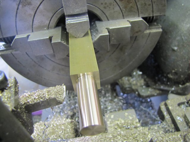
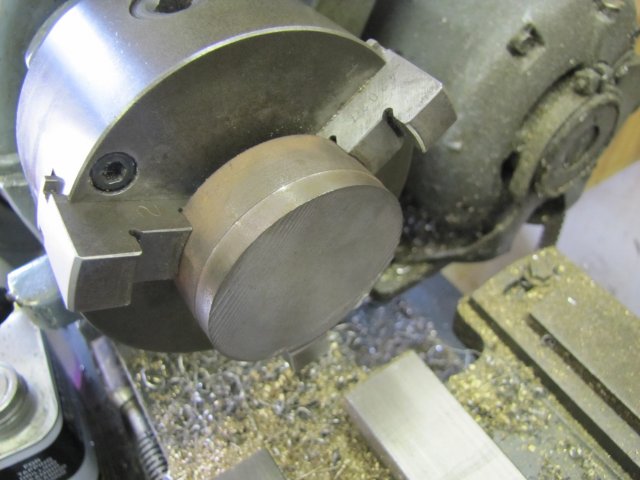
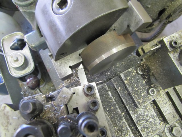
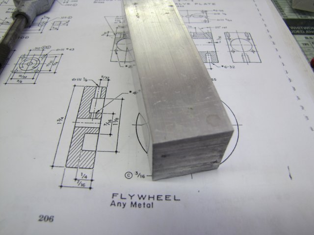
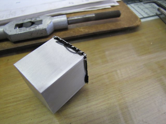
Yesterday, I f@rted around with a block of aluminium. The markings on the 1" square bar are indicative that this is an extrusion, and I expected it to be a bit gummy while machining:
normal_IMG_2472.JPG


It was gummy, and left a lot of burrs from fly-cutting:
normal_IMG_2475.JPG


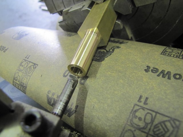
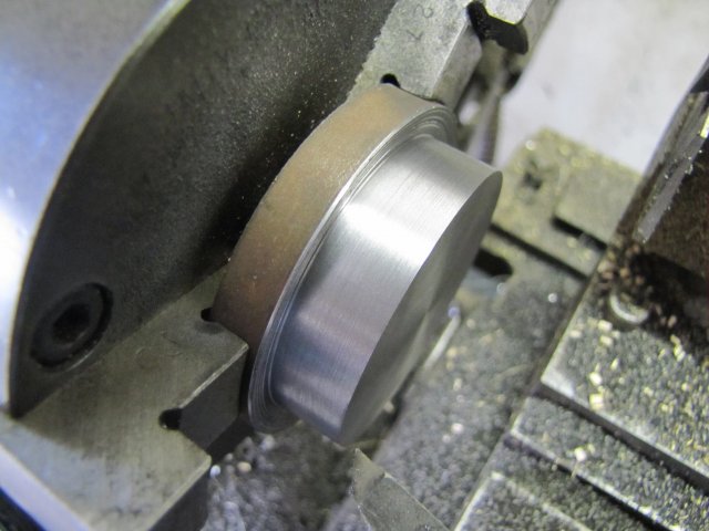
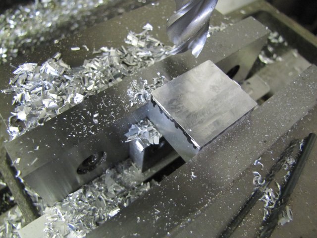
Even though not ideal for the job, it's what I had available, so I carried on trimming it down to size with a 16mm end mill:
normal_IMG_2476.JPG


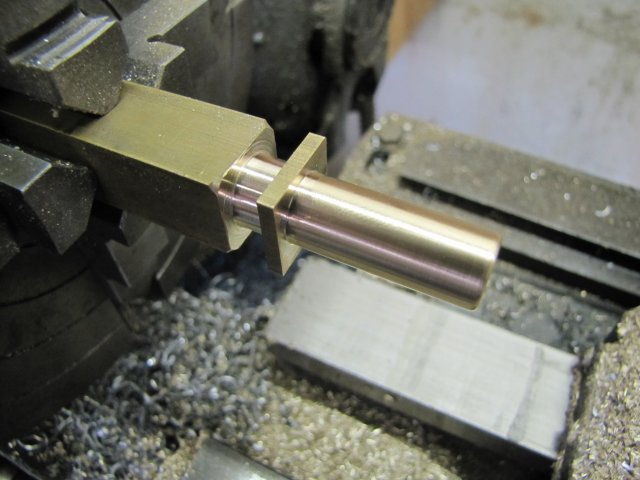
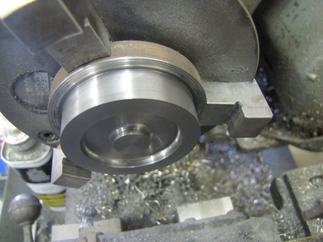
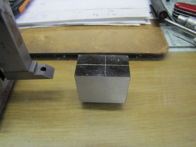
I ended up with the cylinder block and marked it out for the cylinder bore:
normal_IMG_2477.JPG


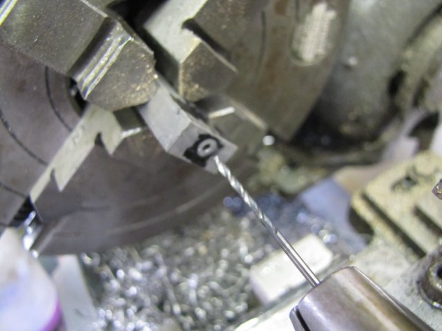
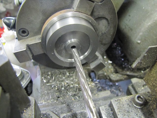
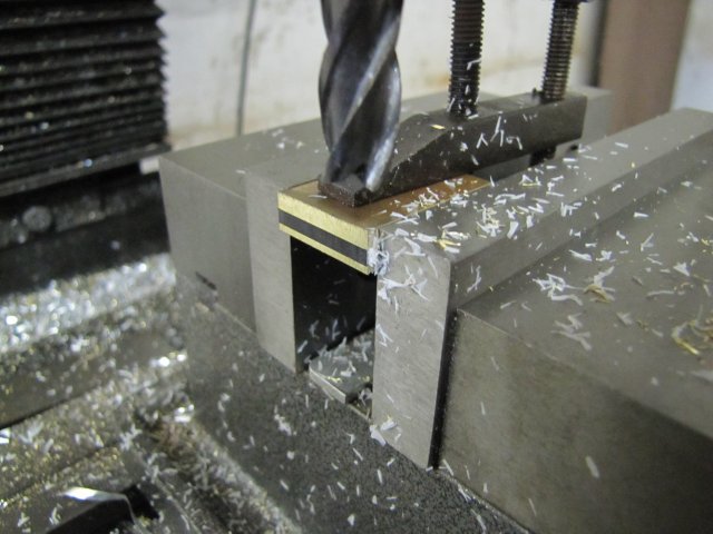
Then I spent quite a while mentally running the machining processes through my head. I was spoilt for choice on machining the bore; it could go on the 4-jaw on the lathe, or I could do it on the mill using drills and a reamer or the boring head. Even though the aluminium was gummy, I opted for the easy way of drilling and reaming, with lots of meths for lubricant while reaming:
normal_IMG_2478.JPG

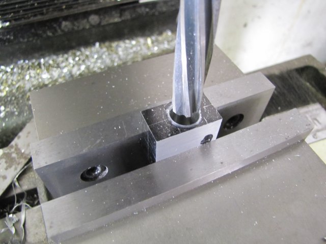
If the reamer left a bad finish, I could have bored out the cylinder with the boring head in the same position, but fortunately it came out OK with just the reamer.

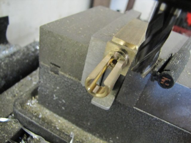
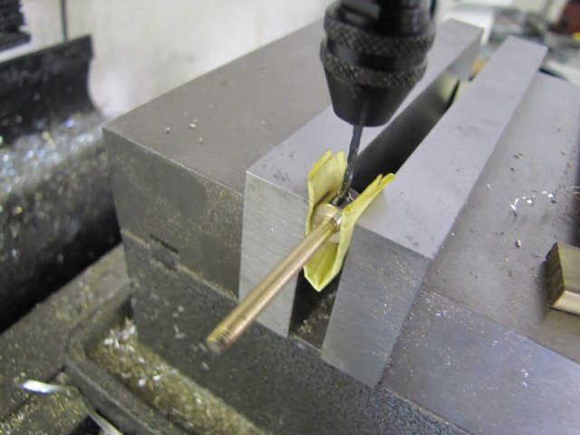
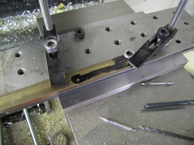
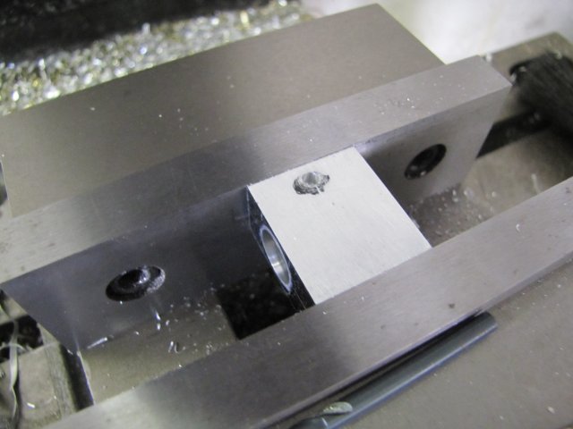
Before starting on the top of the cylinder, I drilled the exhaust passage on the side; it just makes it easier to drill the exhaust port on the top to the correct depth:
normal_IMG_2479.JPG


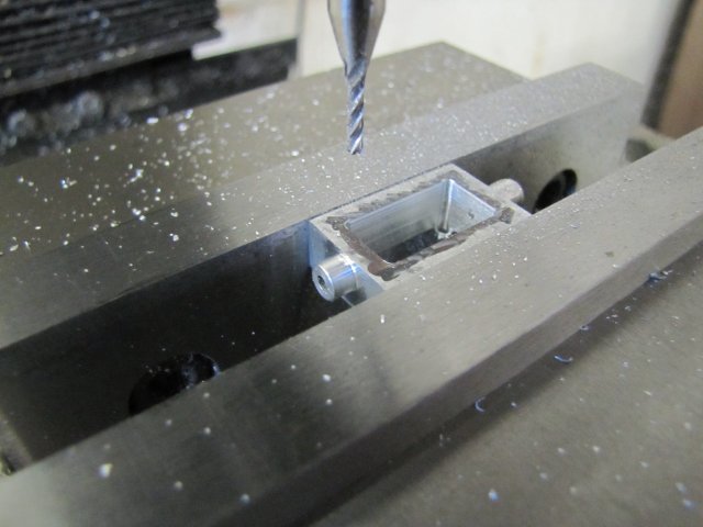
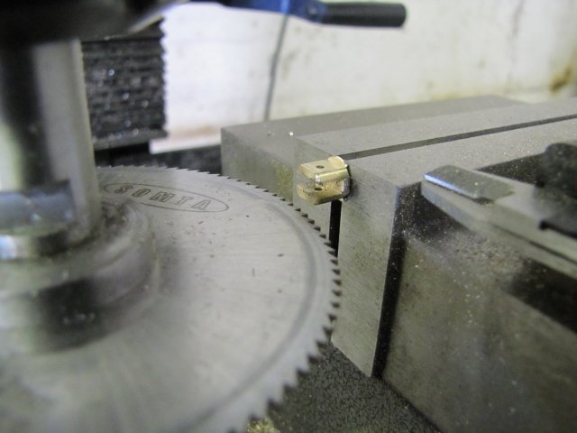
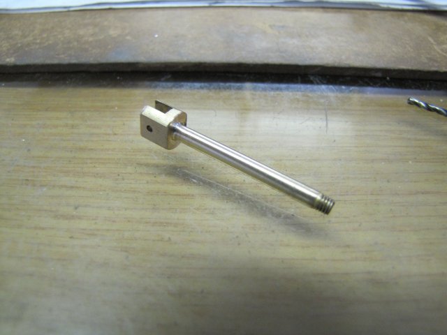
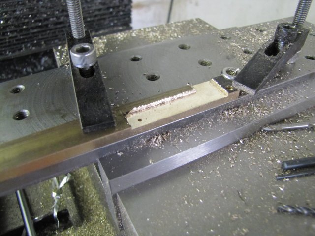
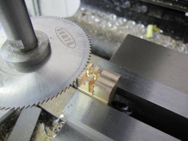
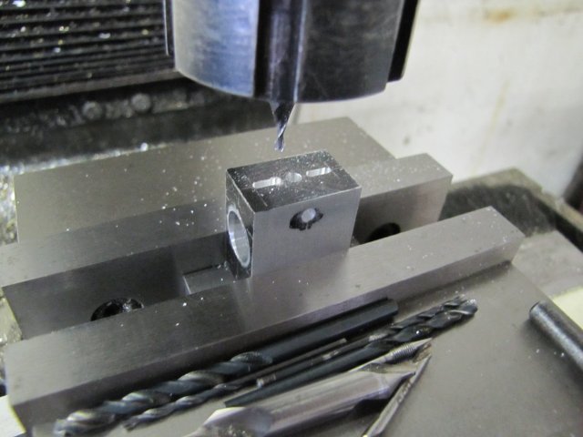
Then I started on the top. Drilled the exhaust port through, and milled the steam passages. The plans call for 1/8" passages 1/16" deep. I don't have a 3mm slot mill, so I used a 2mm one and to compensate for the width, I milled the slots 2mm deep rather than the 1.6mm called for:
normal_IMG_2481.JPG


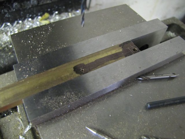
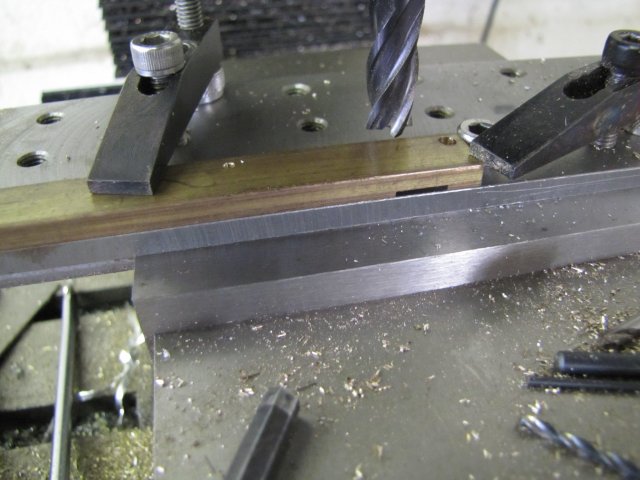
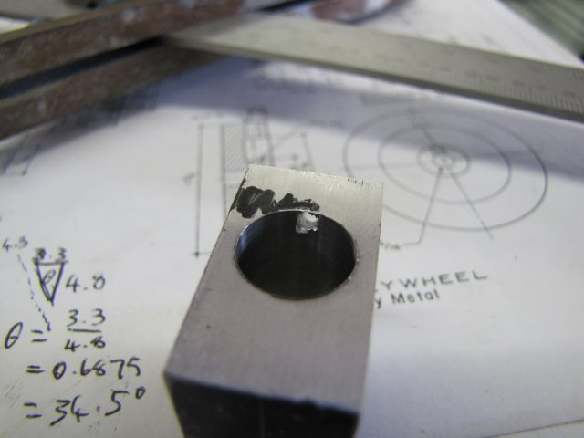
With the ports milled deeper, I had to calculate new angles for drilling the ports through to the bore; a quick bit of rough sketching and trigonometry sorted that:
normal_IMG_2482.JPG


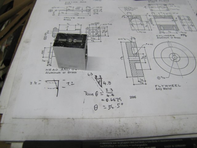
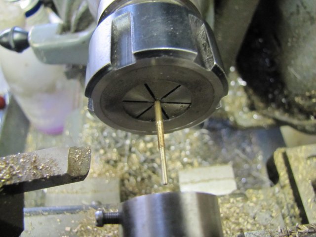
Come on daddy; the maths is boring:
normal_IMG_2484.JPG


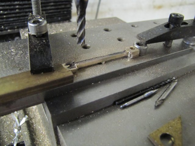
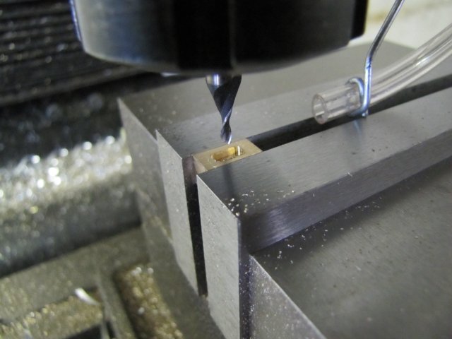
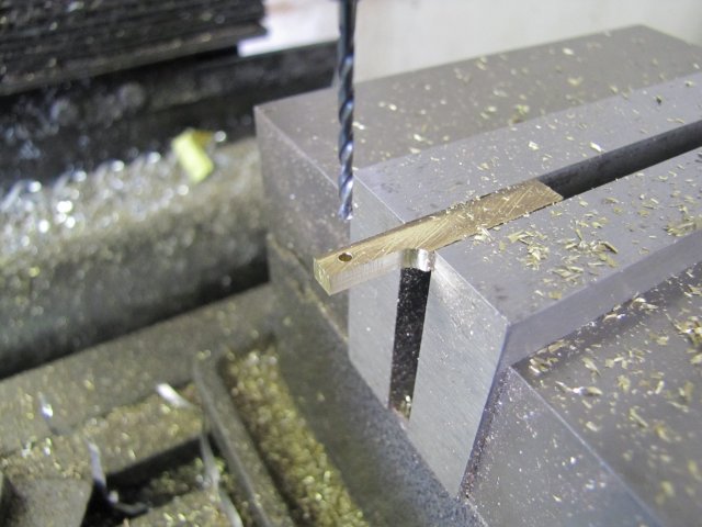
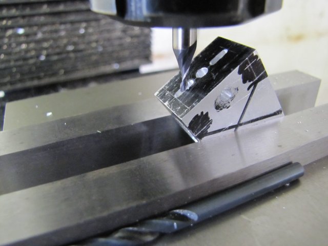
With the new angles marked, I started off the passages with the 2mm center-cutting slot mill:
normal_IMG_2485.JPG

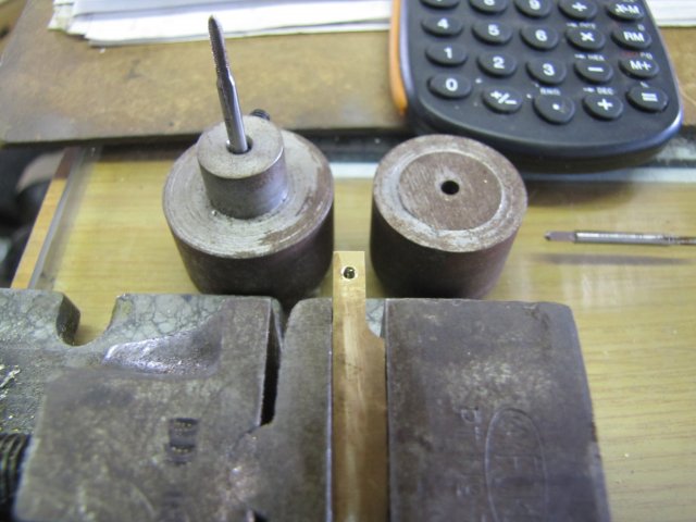
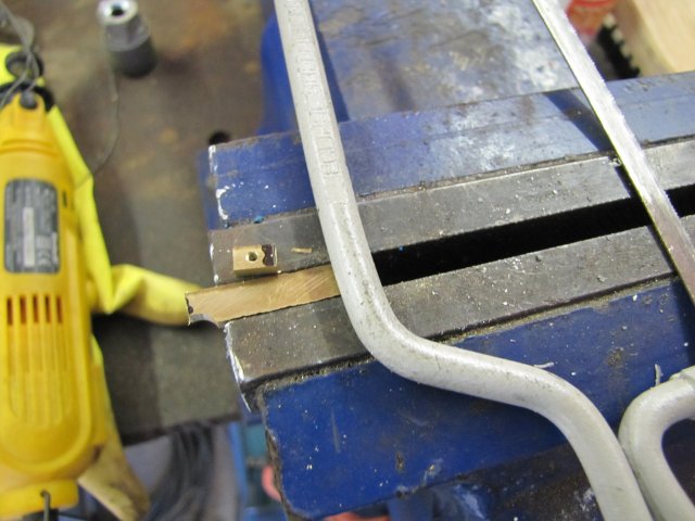
That was followed with a 2mm drill.
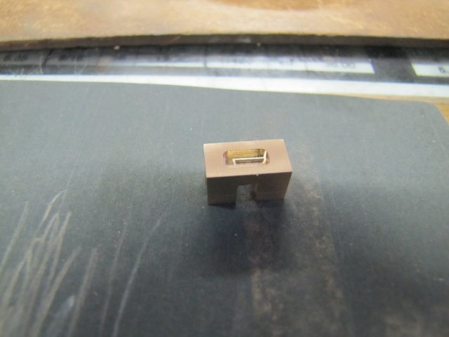
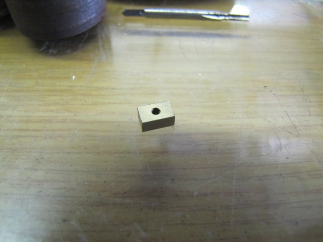
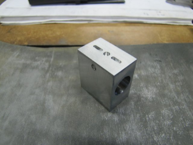
Came out spot-on:
normal_IMG_2486.JPG


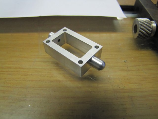
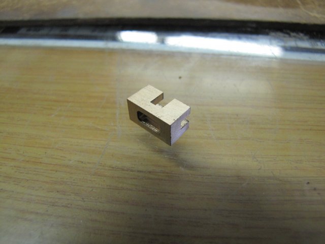
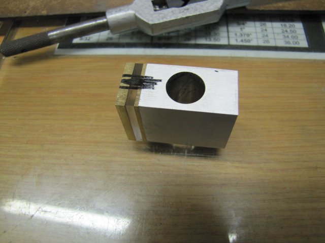
After a quick rub-down on emery, the cylinder block looks fairly presentable:
normal_IMG_2488.JPG


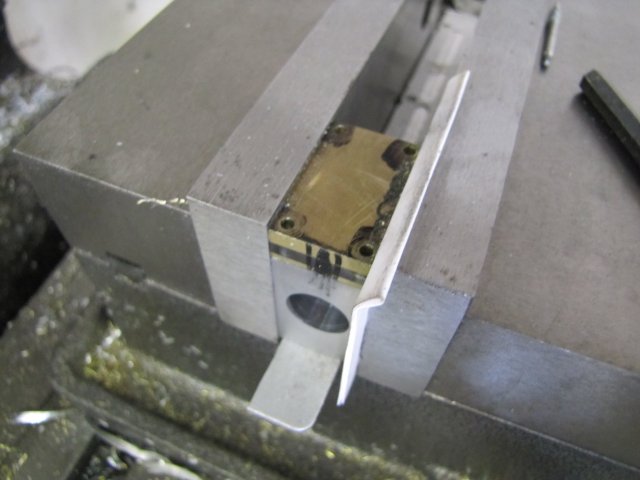
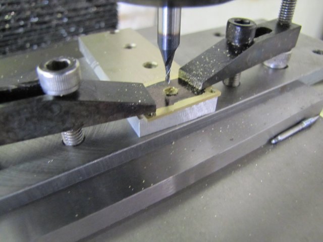
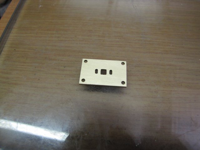
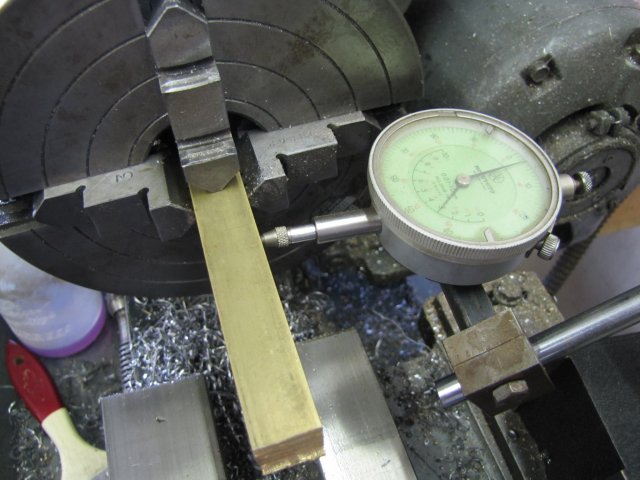
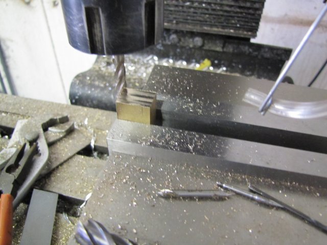
Two bits of brass plate and a bit of perspex followed:
normal_IMG_2489.JPG

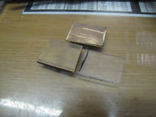
The thinner brass plate is for the valve face, and the perspex and thicker brass plate are for exchangeable valve chest covers; the perspex for running on air and showing off the valve mechanism, and the brass one should I run the engine on live steam at some future point.

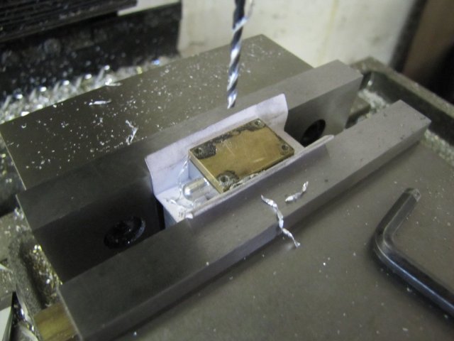
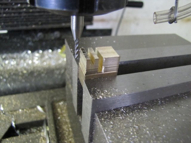
I machined the three down as a sandwich, with the perspex clamped between the brass plates, and the thicker, sturdier brass plate at the top, as end mills are inclined to want to pull up work pieces. With the perspex in the middle, it would be less inclined to want to crack or break:
normal_IMG_2490.JPG


Shop time ran out yesterday before I could carry on; I'll continue today:
normal_IMG_2491.JPG


Regards, Arnold
 
Hi Arnold,

Nice job on the "non-machineable" alu part! Your work looks really fantastic.... :bow: :bow: :bow:

Its a pleasue to follow along!

Regards Jeroen
 
Thanks Jeroen. Fortunately the ali worked OK with sharp toolbits and some methylated spirits :)

I spent six hours in the shop today, and don't have too much to show for it ::)

Stacked up the valve- and cover plates on the block in the mill vise and clamped the lot up with a business card folded double to take up the minute difference in size between the parts, and coordinate-drilled the screw holes - first with a center drill to start each hole accurately, then down to threading depth in the cylinder block with a 1.6mm drill for M2 tapping, and finally 2mm clearance just through the loose plates to the top of the block :
normal_IMG_2494.JPG


Then I started milling out the port holes in the valve plate with a 1.5mm slot mill:
normal_IMG_2495.JPG


The valve plate after a bit of flat lapping. I'm not happy with it; I think I used over-heavy cuts while milling the slots, so they are very untidy. I might just re-do this part to make it better:
normal_IMG_2496.JPG


The steam chest followed from some 8mm aluminium plate. Fortunately this is a better alloy to machine than the bit I made the cylinder block from. I finished the block to near-final dimensions on the width, and chucked it up in the 4-jaw on the lathe to turn the round bits on it, and also to drill the holes for the valve rod. The hole in the back must be 1.6mm, with the one in the front 2mm. I drilled deep enough with the 2mm drill through the block to just reach the point where the 1.6mm hole had to continue - that's about 28mm deep. Then I had to drill the last bit with the 1.6mm drill, whis is fairly short, so I barely had 6mm of it's shank chucked in the drill chuck:
normal_IMG_2497.JPG

My old girl (the ML7) is a bit slow for these small drills at max 800RPM, so it takes peck drilling at a slow feed and frequent cleaning with a drop of meths on the drill tip each time it comes out. This is where I really find an advantage using meths as lubricant on aluminium over WD40 and such; the oily cutting fluids tend to make the swarf cling to the drill bit, thus clogging up the flutes more quickly. The meths just make it slide past, hence I can take deeper pecks while drilling - 3 to 4mm deep pecks are easily done with a 1.6mm drill.

A bunch of milling followed to clear out the hole in the steam chest. I roughed out most of the material with a 4mm 2-flute slot mill, and then followed with many fine passes with a 2mm end mill to get it to size and sort of neat-looking:
normal_IMG_2498.JPG


I used the brass valve cover as a template to drill the holes through the steam chest:
normal_IMG_2499.JPG


All done with the steam chest. After a couple of minutes of rubbing over sand paper to tidy it up; it came out satisfactorily :) - unlike the darn valve plate ::) :
normal_IMG_2500.JPG


Regards, Arnold
 
I had to look up Windhoek, Namibia....You are a good ways South and probably about just about opposite weather from where we are. So you're going into winter....Good time for the shop! Good time for model engines....and this one looks just fine too! Nice work.

BillC
 
BillC, Windhoek is also an exceptionally fine beer brewed in those parts - to German purity laws - only water, yeast, hops & malt are permitted - no addition of corns & sugars allowed. No seaweed extract or any of the other witch's brew of chemicals used by most commercial brewers.

My favourite tipple.

Ken
 
Thanks BillC - Yes, us lot in the Southern hemisphere are going into winter now. Not too bad here in Namiba though; it rarely goes below freezing in winter and basically shop time is good all year round. Even though Namibia's a bit out of the way, it's a stunningly beautiful country - surprisingly the 24th largest in the world and our population is only around 2.6 million people at the moment. I like the wide open spaces, and as Ken mentioned, we have darn good beer here, some of these have won prestigious international awards ;D

This afternoon I started on the cross head. I used a bit of 16mm square brass bar that I have - and as it is already on size on the dimensions, I couldn't allow for any trimming off on the square bits, so I carefully clocked it up true in the 4-jaw chuck:
normal_IMG_2502.JPG

The overhang from the chuck is a bit long, but I didn't want to saw a bit off it - as that results in waste later on. I only have this bit of 16mm square brass, so neither wastage nor failure is an option; it's a great incentive to get things done right the first time :big:

First I turned up and parted off the cylinder head. That was a simple job - I didn't take any photos. Then turned down the outside of the cross head to dimension; I love turning brass, as it's really easy to get a good finish on it:
normal_IMG_2503.JPG


The hole in the cross-head would have been easy to ream, but I don't have machine reamers; only hand reamers and those can't ream all the way into a blind hole because of the taper on the tips. This hole must be smooth and accurate all the way through to the blind bore at the back. Not feeling in any mood to make up a d-bit from silver steel for the job, I drilled the hole out to 7.5mm and used my small home-made boring bar to bore it out to 7.8mm. The boring bar barely fit in the hole:
normal_IMG_2504.JPG


Before moving to the mill, I also cleaned up the back of the workpiece to 12mm - this is for leaving a register ring to fit in the cylinder bore and parting off later:
normal_IMG_2505.JPG


On to the mill; the excess square stock made it easy to clamp up the workpiece in the vise, so this was a quick and simple job, taking care not to take too heavy cuts as material was removed:
normal_IMG_2506.JPG


Finally back to the 4-jaw for parting off. As the register was already turned, I could just part it off without completely re-centering the workpiece in the chuck:
normal_IMG_2507.JPG


The results of today's work:
normal_IMG_2508.JPG

The boss on the cover plate is not to plans - I left it to add something interesting to what would otherwise just be a square cover plate.

Regards, Arnold
 
How do make it look so awesome so fast!?!?!?

Great job!!!!!!

Chris
 
looking great mate
Pete
 
Let's see now....no freezing weather, plenty of good beer, your dog nearby, a nice shop and apparently a pretty good camera. I'm quite sure that you have it made. I also like the 'wide open spaces' idea too. You folks need to require a return trip ticket for visitors or you'll have squatters....taking up space and wanting to drink beer for free, just like here in the USA..... Don't mind me...I get on a soap box once in a while....Your "work" and the excellent photos are very enjoyable.

Watch that Ken guy...he's into a lot of stuff - we'll probably find out that he's a brain surgeon too.... But he drinks beer so he's OK!

BillC
 
Chris, Pete - thanks Gents :)

:big:, BillC, I don't quite have it made, but that's half the fun of life here. Immigration laws are a bit strict; you'll most likely need a return ticket, but anyone from HMEM who pops over here would be most welcome to a couple of free beers ;D. Camera's nothing too fancy; a Canon Powershot SX20 IS; a great all-rounder. Oh, and I'll watch Ken - though its not surprising that he's into a lot of things; down in these areas we have to multi-skill ;D

Today's little bitty bits...

Drilling the mounting holes for the cross-head was a bit of a challenge. The index on the back of it fits the cylinder bore tightly, so there's no room for movement and later "fudging" to adjust things. And to make matters even worse, there was no way for me to center drill the holes first - I don't have spotting drills, and my center drills are all of the short variety...
In addition, the 1.6mm tap drill is barely long enough. I ended up marking out the hole locations on the cross-head, and using my scriber pressing a deep indentation in each location. As the cross-head is a tight fit to the block, it would most likely stay put while drilling; I couldn't clamp it to the block. I carefully drilled the holes by lightly pressing the drill bit into the indentations before starting up the mill motor. After the first hole, I stuck another 1.6mm drill in the hole just to make sure things couldn't move:
normal_IMG_2510.JPG


The cylinder head was a lot easier, as I could clamp it down:
normal_IMG_2511.JPG


Turning up the piston was a really quick job. Here it is half-way done and still 0.05mm over size, with the back side parted off partly, and a good chamfer added on either end. Also, being the normal lazy rotter that I am, I couldn't be bothered to set up a tool to turn the oil grooves; I used a triangular needle file to add them - and got my dimensions slightly out; old eyeball MK1 didn't quite do it:
normal_IMG_2512.JPG

After adding the chamfers and oil grooves, I turned it down to size - 11.98mm to fit the 12mm bore. Then I center drilled it, drilled it 2.5mm for M3 tapping, added a section drilled out to 3.2mm (I'll be using 3.2mm brazing rod as the piston rod) and tapped it M3 before parting it off fully.

On to the piston rod - which was a bit of a challenge to make. First, some 3.2mm brazing rod in the collet chuck, turned down to 3mm for 1/8" and threaded M3 with the tailstock die holder:
normal_IMG_2513.JPG


Then I turned a bit of brass down to a still-tight fit in the cross-head, and drilled it out 3.2mm with a generous chamfer in the start of the hole before parting it off. I left the parted off side a bit rough around the center hole - which made the bit a tight slide along the brazing rod. Seems a lot of boo-hah over a simple bit, but there's some method to my madness. As I wanted to silver solder the brass bit to the rod, it would need cleaning up later, and if I made it a good fit in the cross-head, it would be too small after cleaning it up after the soldering process. The chamfer was needed for a place for the solder to dam into and thoroughly join both parts, as the clearance between the hole and the rod was too small for the solder to properly wick in. In retrospect, it would have been a better idea to file slight flats on the rod to leave more space for the solder to wick in; too late now though; the job's done.
Here it's fluxed up and ready for soldering:
normal_IMG_2514.JPG


I heated the lot from the right-hand side till it glowed dull red, and just touched the solder stick to it - job done:
normal_IMG_2515.JPG

It looks horrible doesn't it ? :big:

Oh well, after a bit of cleanup, it looked OK, and I could carry on - drilling the cross-pin hole:
normal_IMG_2516.JPG


Cut slots and flats with a slitting saw - very carefully, as this is not a very stable set-up:
normal_IMG_2517.JPG


Piston rod done:
normal_IMG_2519.JPG


Some 4.8mm brass bar, and a couple of holes poked in it:
normal_IMG_2520.JPG


With the tooling plate installed in the vise, I clamped the lot down. The cap screw screwed down on the right of the workpiece is acting as a stop, as the part needs to be flipped around for some up-coming machining. I've mentioned before that I'm a lazy so-and-so, and this is more laziness ;D:
normal_IMG_2521.JPG

Oh, and have I mentioned how much I love this tooling plate ? - It's some of the most useful tool-making time I've spent!

A bit of milling:
normal_IMG_2522.JPG


Flipped over after de-burring, and ready for some more:
normal_IMG_2523.JPG


And even more milling - here I've already removed the clamp on the right; that was in place while milling:
normal_IMG_2524.JPG


A couple of facets milled off around the edges:
normal_IMG_2525.JPG


And a short while later after some filing and emery, I ended up with the connecting rod done:
normal_IMG_2526.JPG

This was a quick job; took me just three hours to make, including a couple of smoke breaks, a visit to the kitchen for coffee, scratching Zorro's the mutt's head, time spent pondering the machining steps to take, and about 30 minutes actually machining it and 30 more with the files and emery :big:

The bits are coming together now - and they even seem to fit :D:
normal_IMG_2527.JPG


Regards, Arnold
 
Lovely work Arnold - your workrate puts me to shame.

When you need a long centre / spot drill - just thin the chisel point of a drill down to the exact centre - A'La a spotting drill and it works just fine.

You can do this on the corner of a bench wheel or use a
Dremmel.

BillC - no brain surgeon - my medical knowledge goes no futher than band-aids.

As Arnold said - in our neck of the woods you have to multitask.
Most of my engineering has been in automotive but having my own business designing machines has dragged me into mines, explosive bunkers and even beneath a reactor.

Hey - now that I think of it one of my robots is being used for brain surgery - proton beam therapy - the patient is mounted on the robot (in a bed or chair) with the targeting mask being picked up by cameras so that the computers can orientate the tumour into the beam path.

http://www.iucf.indiana.edu/proton/docs/denton02a.pdf

(This is in Indiana - copied from Ithemba labs in Cape Town - gets only a brief mention in the article.)
Photo attatched shows robot with most of its additional coverings removed (In practice you can't see it - don't want to frighten the patients any more than they already are - life threatening illness and all.)

Ken


robot.JPG
 
Arnold,
Very impressive work, and you make it look so easy! Welcome Back!

Ronald.
 
Thanks Ken - I do have slow workdays like today though.

Ronald, Thanks :) - The simpler bits does feel easier to make than when I started with model engineering - but then again, my tooling arsenal has increased quite a bit as well, so many of the jobs are much easier to do. It all still takes quite a bit of effort and time though, but that's part of the fun :)

A single bit made for today, as well as the first boo-boo of the build.

First I turned some 2mm brazing rod down to 1.6mm for 3/8". Brazing rod is tough to turn, and when it's this thin, the toolbit must be super sharp and dead on center:
normal_IMG_2528.JPG

The photo makes the turned piece look taper, but it is actually pretty close to parrallel with the tailstock side only 0.01mm thicker than the headstock side - that's from flexing, but is close enough for this bit.

The piece was extended further from the chuck, and I ran the 2mm die nut over it to add some threads:
normal_IMG_2529.JPG


Then I made the boo-boo - I cut it off too short after miscalculating the length, and had to re-do it. The second one didn't come out as well as the first - the die nut caught on the turned-down bit, but I was in no mood to re-make it yet again, so I silver soldered a block of brass to the end, and finished the part. It operates smoothly in the valve chest, so the light threads on the thin section won't be a problem:
normal_IMG_2531.JPG


Regards, Arnold
 
Still looking fantastic Arnold. Coming together very nicely now!!!

Bill
 
Ken I said:
Lovely work Arnold - your workrate puts me to shame.

When you need a long centre / spot drill - just thin the chisel point of a drill down to the exact centre - A'La a spotting drill and it works just fine.

You can do this on the corner of a bench wheel or use a
Dremmel.

BillC - no brain surgeon - my medical knowledge goes no futher than band-aids.

As Arnold said - in our neck of the woods you have to multitask.
Most of my engineering has been in automotive but having my own business designing machines has dragged me into mines, explosive bunkers and even beneath a reactor.

Hey - now that I think of it one of my robots is being used for brain surgery - proton beam therapy - the patient is mounted on the robot (in a bed or chair) with the targeting mask being picked up by cameras so that the computers can orientate the tumour into the beam path.

http://www.iucf.indiana.edu/proton/docs/denton02a.pdf

(This is in Indiana - copied from Ithemba labs in Cape Town - gets only a brief mention in the article.)
Photo attatched shows robot with most of its additional coverings removed (In practice you can't see it - don't want to frighten the patients any more than they already are - life threatening illness and all.)

Ken

I read an article recently about the robotics that are becoming the surgeons of tomorrow (with the Surgical MD in the forefront of course) and doing it in magnificent fashion so that very little incision is needed. I would have thought someone as modest as Ken would have mentioned it.....Too much Ken!

Arnold, Multitasking....: I always thought that multitasking was doing your job plus the job of many around that don't quite have the attention span or desire....Yes, I know what you mean though, and being poor (such as I) necessitates multitasking if one desires to get something done. I know of something that I could do for you in your shop though....drink lots of your beer and build you a CNC mill.....darn; I wish I could really do that!

Great and fun project to follow along with Arnold - you're having fun and it is very evident!

BillC
 
Thanks very much Both Bills :)

Yes, I'm having fun ;D. While I love my day-job as "IT Guy", the rewards are different. If one does a good job in IT, one gets long-term satisfaction of systems running/programs not crashing and happy users and so on, but rarely at the end of each work day a sense of being able to show and touch what was done for the day. Model engineering bridges that gap - even if I made a boo-boo there's something to show for the work :) Guess I'm lucky both ways then!

Today I started off on the valve - but before I started, I fashioned up a Rube Goldberg style air supply from the compressor. There was lots of small milling going to go on, and I didn't buy the new compressor for nothing! A block of bronze (the plans call for brass, but bronze would be just dandy) - and I started milling it to size; no mark-out or anything; this was going to be done by the mill dials only:
normal_IMG_2532.JPG


The 6mm end mill I used to trim the block down is definitely in need of replacement :big: - it left a lot of steps on the sides. I used a 2mm end mill to mill the central slot, and the "other side" of the valve; the air flow was set to go over the workpiece, and this pulled the chips right out of the slots while milling:
normal_IMG_2533.JPG


After milling the cross-slot, I used a slitting saw to slice off the valve from the parent stock:
normal_IMG_2534.JPG


After a quick de-burr, I flipped the valve over and milled the port face with a 1.5mm slot mill; this is where the air supply really came into it's own. Not much pressure; just 10 psi, but it cleared the chips out of that hole making it a breeze to finish:
normal_IMG_2535.JPG


After some quick flat-lapping with 800 emery on the glass plate:
normal_IMG_2536.JPG


And cleaning up on the sides, and ends, the valve was finished:
normal_IMG_2537.JPG


Then I started on the valve nut - once again no mark-out and just using the mill dials to size it on 3 sides and drill the tapping hole:
normal_IMG_2538.JPG


Tapped it M2 with my bad-looking handle and tap guide; Elmer specifies the tapping here as "Close", so instead of tapping all the way through with the last tap in the set, I stopped it when I felt it just starting offering less resistance to tapping torque before going all the way through:
normal_IMG_2539.JPG


Just for exercise, I used the junior hacksaw to saw off the nut:
normal_IMG_2540.JPG

An then filed it down to size on the sawn-off side.

After a light rub-down on emery, the nut came out to satisfaction:
normal_IMG_2541.JPG


The valve and nut fits just dandy in the steam chest, with about 0.1mm of free play on the valve to the nut ;D:
normal_IMG_2543.JPG


Then I turned up two crank screws from some 5mm hex brass rod:
normal_IMG_2544.JPG

To my horror, I just noticed some burrs left on them :-[

Things are finally getting to a point now; I laid out all the bits to check what's still missing:
normal_IMG_2546.JPG


The to-do list - surprisingly long still!!!
1. Obviously, the flywheel - I hope to get cracking on that tomorrow.
2. There's a couple of parts that still need cleanup to remove burrs and toolmarks. The column actually still needs quite a bit of work now that I look at it.
3. The cylinder block needs to be tapped M2 in 12 mounting holes - Yes, I'll be doing studs 'n nuts again, and I can't do the studs before a final cleanup of the block.
4. Make said nuts from brass/bronze... there's a lot of tapping and filing work in my future :big: Fortunately I have quite a bit of M2 threaded bronze rod left.
5. A lick of paint - yes, this time some parts will get painted!
6. A final once-over with a buff on some parts and a bit of polymer car polish on those.
7. Wooden base - and all the work associated with that ::)
8. Final assembly - hopefully it will run :-\

Regards, Arnold
 
Thanks for the update Arnold!!!

The ruler gives me some idea to it's dimensions, i imagined it to be a lot bigger that that!

Great work as usual and i love the Heath-Robinson air blower!!!!

Looking forward to seeing this one completed!

Andrew
 
Andrew, Chris, thank you gentlemen.

Yes, it's a smallish engine; in fact, all Elmer's engines are fairly small. Sorry, I forgot to add the "scale" to many of the pictures :-[ - Now where's Zee - he'd give me a right grilling for that!

Today the flywheel received attention

I started off with a bit of 55mm cast iron I had lying about; slightly too large and a lot will be wasted, but that's what I had on hand:
normal_IMG_2547.JPG


My chuck's inside jaws can't open up large enough to safely hold it, so I had to use the outside jaws. With the stock on the short side, I had to figure out a way to get in there to turn it, and also checked for adequate clearances all round so that I wouldn't run anything into the chuck jaws:
normal_IMG_2548.JPG


Turned down to size; not the greatest finish, as I used the toolbit shown in the previous photo "for the wrong job" :big: :
normal_IMG_2549.JPG


The normal toolbit I have for trepanning out flywheels was a bit big for this one, so I had to grind up a new narrower one. Turned out OK, but I had a tiny bit of chatter in the rounded corners:
normal_IMG_2550.JPG


Then I just center drilled, drilled and reamed the flywheel to fit the crankshaft:
normal_IMG_2551.JPG


Then I flipped the flywheel in the chuck and cleaned down the other side and trepanned it. I spent some time thinking about milling spokes in the flywheel, but decided against it, and just went for drilled holes. To be a bit "otherwise" I went for seven instead of the traditional six - that meant calculating the odd angles and practicing dialling those in on the rotary table:
normal_IMG_2552.JPG

I couldn't drill the holes all the way through, for fear of running into the chuck jaws, so I drilled them till I could just feel the drill bit want to run through.

Then finished the holes on the drill press with the cross-vise. The drill press is much less rigid than the mill, so the drill bit follows the pre-drilled holes easier and hence much neater:
normal_IMG_2553.JPG


As a final step, I drilled and tapped a hole at an angle in the hub to take an M3 grub screw (set screw). Elmer's plans show the grub screw through the outer rim, but I don't like that too much, hence the digression from the plans. That completed machining on the flywheel:
normal_IMG_2554.JPG


Regards, Arnold
 
Just now got caught up with this one, Arnold. It's a fun build log for a nice little engine.
I know it was days back, but glad you came out of the fire incident okay!

Nice new compressor that you bought there. Now you just need to buy a pack of M&Ms. ; )

Dean
 
Back
Top