Anybody guess what this is going to be???

Home Model Engine Machinist Forum

Help Support Home Model Engine Machinist Forum:

This site may earn a commission from merchant affiliate links, including eBay, Amazon, and others.
I am no alternator expert but I think 16 poles (8 pairs) will produce "in theory" twice the voltage at twice the frequency versus an 8 pole (4pairs) configuration. One one hand you get more voltage on the other hand core losses wil almost quadrupled. Having a solid core keeping the frequency low would be an advantage.

With model alternators the typical problem is getting enough voltage at reasonable RPM.
Keep the gap (rotor stator clearence at minimum.
Use small wire and many turns, wires around #30 gauge are just right to wind not too fragile not too stiff, and still can carry 0.5A in an open frame environment.
Peak induction takes place when the most magnetic field "lines" crosses the wire. When you have the same number of poles in the stator and rotor, this happens simultaneous on all coils, thus generating a perfect sine wave and adding the voltage of all the coils. If the rotor's poles are different from the stator, what will happen is, that peak voltage will be reached in some coils and the others, still not thus, the sum will be vectorial and will be less than it could
 
I think I could use 8 magnets if I wrapped every other coil in opposite directions. Would that work? That would give me half the frequency, which is no matter, but not sure what it would do to the voltage.

Chuck
 
I think I could use 8 magnets if I wrapped every other coil in opposite directions. Would that work? That would give me half the frequency, which is no matter, but not sure what it would do to the voltage.

Chuck

You can use the 16 magnets and still get 8 poles. I can draw the way to wind the 8 coils to get the 8 poles if you want.

It's easy to calculate the amount of turns needed to get the required voltage by winding a few test turns and running the alternator at your required speed, before winding it permanently.
 
I think I could use 8 magnets if I wrapped every other coil in opposite directions. Would that work?

Yes it would work. Basically a continuation of the image below.

imagei1a.jpg
 
I received my magnets from KJMagnetics and installed 8 of them on my armature. I've done a bit of testing and results are a bit disappointing, but I think I will be able to get it where I want it. Here's a picture with the armature withdrawn for illustrative purposes.

IMG_2821_zps7ab8977c.jpg


I've installed 8 magnets and have 200 turns of #27 wire on one pole of the stator. Turning the armature at somewhere around 1500 RPM's and feeding the output through a full wave rectifier gives me .25 volts. Multiplied by 8 would give me 2 volts. That's probably enough to light an LED but if I add another 8 magnets, I'm thinking I'll get 4 volts and if I add 16 magnets I should get 6 volts. Since the #27 wire is rated at .287 amps, I'm guessing an incandescent lamp is out of the question.

As an added note, I'm using a 1 1/2 HP air compressor to run a model engine which in turn is turning a dynamo that can maybe light an LED. Not the most efficient system in the world, is it? :hDe:

Chuck
 
Polyethylene might make cutting easier, but its not doing anything for concentrating the magnetic force that does the real work here. Maybe if you machine the stator (outer) piece to sink some iron laminations from old wall wart transformers inside the coils you would see a bigger output.
 
Also make sure those magnets are north/south on the long edge and not the ends like more common bar magnets.
 
your full wave rectifier decreases output voltage about 1.2V
Try to build your own rectifier from LED diodes and short
LED rectifiers + and - pole.
Or connect LEDs directly to coils.
Then use modern low consumption LEDs.
Build rotor drum from soft steel and glue magnets on the surface of
drum.
In your plastic generator you do not have any metal magnetic
core /path/ to lead magnetic flux from magnets through coils, so your
output voltage is low and "soft".
 
You can try using a schottky diode. They have very low voltage drop, and they can be found in just about any computer power supply. Often these are diode packs though, found in TO-220 or TO-247 packages and are basically 2 diodes that share a common cathode, so you would need two of them to properly rectify AC.

Something like this: Linky

With only 0.25V drop.
 
Is the rotor made of some kind plastic?

It should be made of low carbon steel, the "softest" iron we can find.

The rotor need to be axially as thick as the magnet as it is shown in the picture. Depth of the ring below the magnest could be about 2 or 3 times the magnets thickness to center can be much thinner and of any material.

As was already pointed out there must be a complete loop of iron going between to adjiacent couils and magnets with al little air gap as tolerances allow.
 
So I removed the single winding and then wound all eight stator coils, 200 turns each with alternating coils wound in the opposite direction. Boy, glad I don't have do that 8 hours a day to pay the rent. That is mind numbing work!

IMG_2822_zpsa5bbbcd7.jpg


I also epoxied another row of magnets on the armature. I broke one in the process, so I'll need to await my order to install the last magnet. As an aside, I discovered that JB weld does indeed have some kind of magnetic material in it. Don't know if its steel, iron, cobalt or what, but the gooey mix is most definitely attracted to the magnets.

Chuck
 
Because it takes energy to make energy, you should feel it "cogging" when you rotate it by hand, and its output will be proportional to that effort. Gives you a quick test without having to hook up a whole lot of test equipment.
 
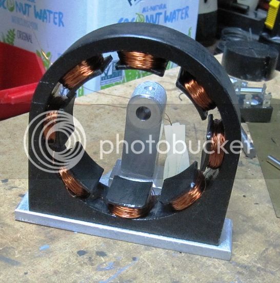
Just a quick progress report here. I wasted a week thinking I had ordered more magnets when in fact I hadn't. So it took another week to get a second batch of magnets delivered. Previously, I had 2 magnets per pole but was missing 1 magnet on 1 pole (breakage).

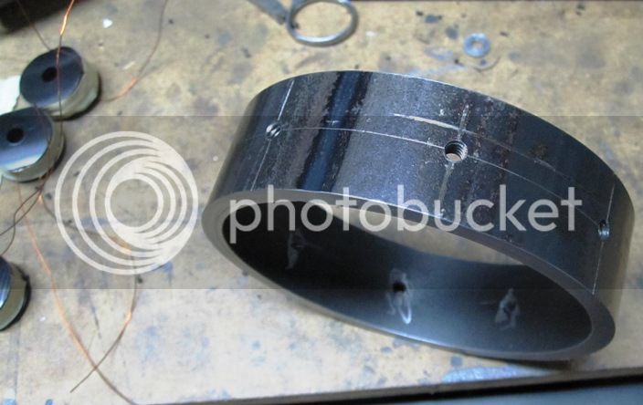
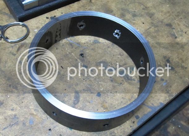
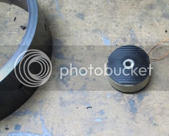
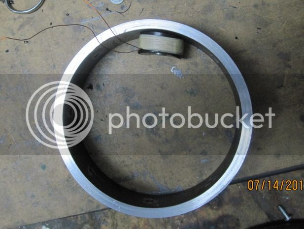
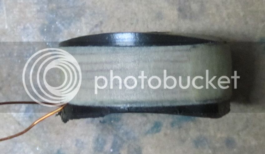
When the new magnets arrived, I installed the 1 magnet needed to complete the 2-magnets-per-pole armature. When I test spun it with my cordless drill at around 1500 RPM, I measured right at 4.0 volts AC. So, I (finally) located my stash of bright green LED's and hooked up 18 of them in parallel, every other one wired in the opposite direction. Then I hooked up the alternator with no rectifier, just straight AC, all 18 LED's lit up very brightly. So I'm pretty happy with it at this point. However, I'm planning to build another stator using a 1" length of 4" pipe, 1/4" wall. The poles will be made up with steel cores that I can wind separately, then attach to the stator ring. Probably won't be the most efficient set up in the world, but should give me more power. I do want to put some kind of load on the engine and I don't think the current setup with LED's is going to do it.

Chuck
 
I started work on a steel core stator. I'm using a 1 1/8" long piece of 4" OD, 3.5" ID steel pipe as the outer ring.

IMG_2870_zps7feababf.jpg


IMG_2871_zps3bf06c0e.jpg


The coils are wound on HDPE plastic spools that started out 1" x 7/8" x 1/2" thick. The center part of the spool is 3/8" diameter with a 1/4" hole through the center and winding space is about 1/4" x 1/4" or a little less since the windings don't go all the way out. There are a total of about 260 turns of #28 copper wire per coil which is about 25% more than my other stator.

IMG_2872_zpsb71b926b.jpg


IMG_2873_zps0a0d810b.jpg


IMG_2874_zps4868ec0a.jpg


I profiled the inner radius of the coil form using a fly cutter on my mill/drill to cut the concave curve with the coil form held vertically on the outside edge of the vice jaws. I formed the outer radius by mounting the coil form on the end of a 1/4" diameter expanding mandrel, then clamping the mandrel in the round tool bit hole on one of my boring bars and swinging the outside of the coil form at the proper diameter in my lathe. Each coil form will have a 1/4" diameter x .4" long steel rod with a very thin, 5/16" diameter flat head on the inner end and a 6-32 threaded hole in the other end. Recessed, 6-32 socket head cap screws from the outside will screw into the outer end of the rod and secure the coil forms to the stator ring.

Don't have any idea how much cogging will be an issure or what kind of power I will get out of this thing or if my engine will even turn it. It's all a learning experience at this point.

Chuck
 
That should make winding a lot easier. :)
As much iron or ferrite you can get in the center of the coil the better. Picture how the two halves of an E core work together to concentrate the magnetic flux as probably ideal.
 
Solid steel is not efficient. But with the low magnet coverage the load on the engine (drag) might not be too bad.

Greg
 
Hi Chuck,
Are you doing away with the silicon steel? Will be following your thread.

Hey Gus, never had any silicon steel, just working with what I have.

Chuck
 

Latest posts

Back
Top