


rythmnbls
Well-Known Member
- Joined
- Jan 14, 2012
- Messages
- 115
- Reaction score
- 31
Inspired by a couple of threads by forum member Bill S, I decided to give my X2 mill some extra rigidity and Z travel. Here are a few photos of progress.
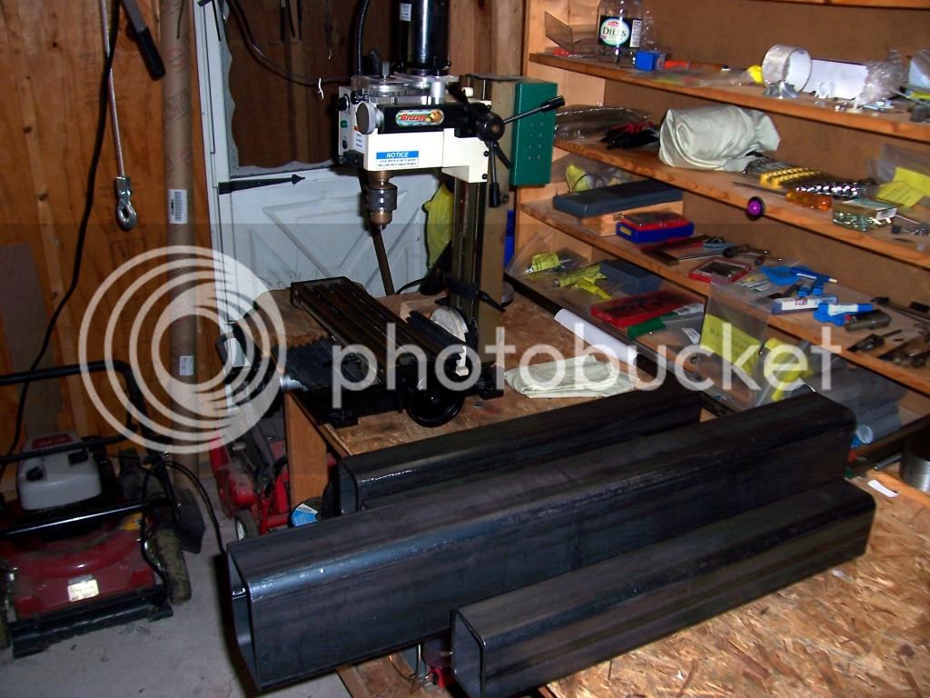
Photo of the starting materials and the unsuspecting mill in the background. Shown are the base materials - 3"x4" square tubes with a .375" wall thickness and a 4"x6" square tube with a .375" wall thickness destined for the column support.
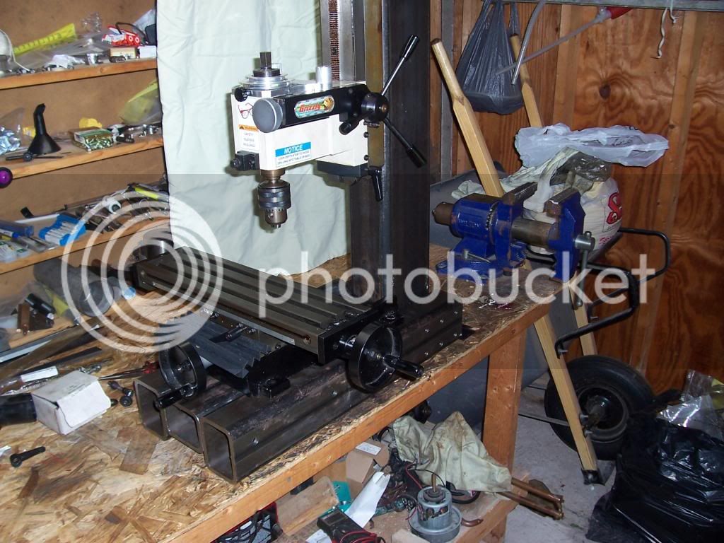
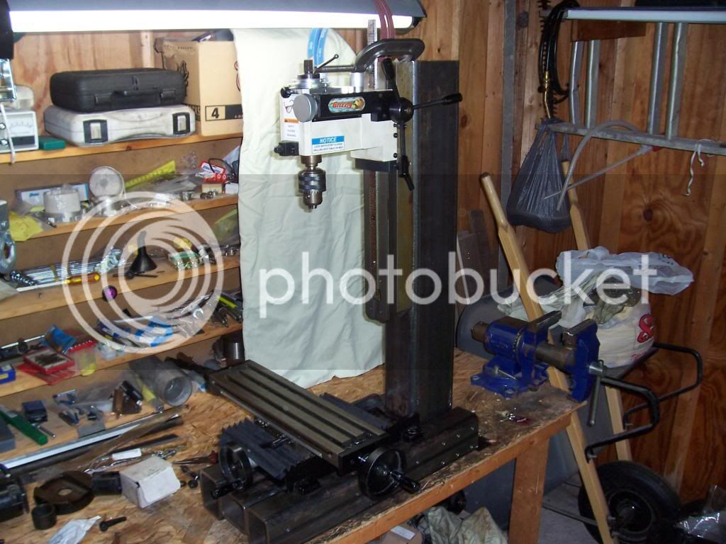
Photos of the assembled base showing the extent of the Z travel. There should be plenty of room for the rotary table with a 4 or 3 jaw chuck and work piece which is a machining operation I could never do previously.
I still have to mount the extended Z rack, and bolt the XY table to the base, tram all axes and throw some paint on it.
Some links to the original threads by Bill S
http://www.homemodelenginemachinist.com/f28/small-x2-mod-7479/
http://www.homemodelenginemachinist.com/f28/x2-upgrade-update-7779/
http://www.homemodelenginemachinist.com/f28/x2-mods-finished-7846/
Thanks for reading.
Steve.


")


