Alternative Firing

Home Model Engine Machinist Forum

Help Support Home Model Engine Machinist Forum:

This site may earn a commission from merchant affiliate links, including eBay, Amazon, and others.

Barracuz

Whatcha readin?
Joined
Feb 17, 2016
Messages
9
Reaction score
2
So has anyone experimented with diffrent firing orders in multicylinder engines?

Im not talking about which pair or set of pistons fire but for example having pistons fire at diffrent times. For example a 4 cylinder engine instead of having a pair fire every 180° have one cylinder fire every 90°. Similar to how the audi 5 cylinder fires a single cylinder every 78°
 
A 4 stroke engine needs 2 revs to complete a cycle. So 720 degrees. As already stated. You can build a 4 cylinder with crankpins at 90 degrees to each other. Some of the newer Sport bikes have this arrangement. But what you get runs more like a large twin cylinder, than a 4 cylinder in that the power strokes overlap a 90 degree period. A 4 cylinder single plan crankshaft fires, Bang ... Bang ... Bang ... Bang ... a Dual Plane crankshaft fires Bang.Bang ...... Bang.Bang .....

Best way I can describe it. Those engines run 17500 redline, put out 100hp with the engine displacement of a 10hp big lawnmower.
 
Yes, most modern DIS ignition sytems fire on every TDC they fire cyls in pairs as running mates... the reason for the importance of the precious metals on both the ground and positive electrodes of the spark plugs
 
Yea I meant 144 and talking about 4 stroke.


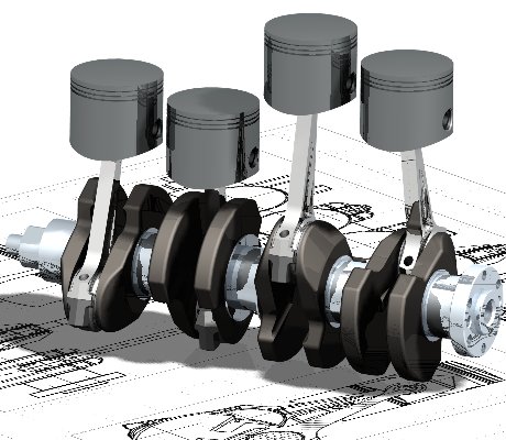
But a convential 4cyl 4 stroke has 2cyl fire at a time so it takes 720 degrees of crankshaft rotation for all cylinders to fire once. For example in this picture where all cylinders are at difrent degrees of rotation.
Cad_crank.jpg


I know yamaha sorta uses a cross plane but has a 1-2-34 firing order has two singles fire alone and the last two fire twice
 
But a convential 4cyl 4 stroke has 2cyl fire at a time

Not true.

In the 4 cyl, 4 stroke, 2 cylinders are at TDC at the same time but they do not fire at the same time. Usually 1 and 4 are at TDC when 2 and 3 are at BDC. With 1 firing and a 180 degree rotation 2 and 3 come up to TDC. one of the 2 cylinders fires and a 180 degree rotation brings 1 and 4 to TDC again. This time 4 fires as 1 is starting it's intake stroke. Again 2 and 3 come to TDC and the other cylinder fires again. Timing looks like this.

0 degrees #1 fires
180 degrees #2 fires
360 degrees #4 fires
540 degrees #3 fires
720 degrees #1 again and so on

You can swap 2 and 3 for a 1-3-4-2 firing order. Typical 4 cylinder with a fire every 180 degrees. Cant get much more even than that.

AH ok I thought they would normally fire twice like a standard 2 cyl.

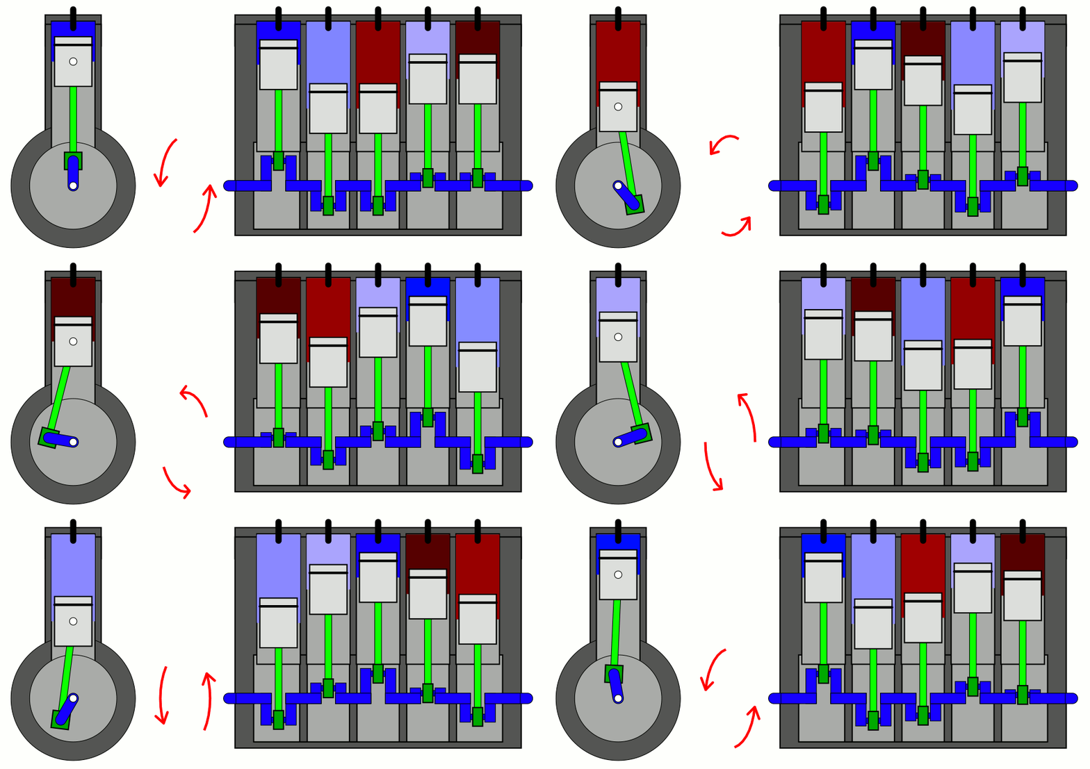
Reihenmotor_F%C3%BCnf_Zylinder.gif


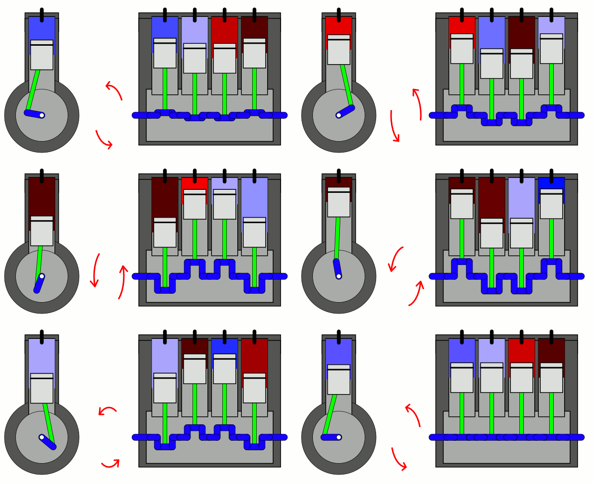
Reihenmotor_Vier_Zylinder_1-2-4-3.gif


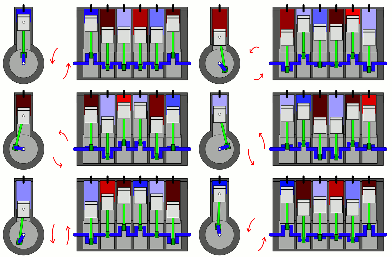
Inline_6_Cylinder_with_firing_order_1-5-3-6-2-4.gif
 
While it is true the spark plug fires every revoloution (most engines today) the second firing is called a waste firing, as the engine is just completing the exhaust stroke and beginning the intake cycle, no power is produced as there is nothing to burn. so it does not count in the course of running.

Current electronic ignition systems use a timing ring crankshaft mounted, it looks like a odd gear, with one tooth missing, or spaced differently. There is a pickup coil, which signals each time a tooth passes the coil, when the odd space passes, the system calls that begin counting, it records the time until it passes again, and figures the time, therefore the rpm, and follows a digital map that tells it which cylinder to fire and when.

Because the timing ring is crank mounted, its easier to have a Waste Firing.
All this is way beyond anything we will deal with here. Well almost everything.


How could waste spark be eliminated on a model engine? two hall sensors one on the cam and the other on the crank?
 
If one builds a multicylinder I.C. engine the simplest way to eliminate the waste spark is to build a conventional type distributor. Most all of my distributors are the Hall trigger type with one magnet mounted internally on a small angle bracket. This is positioned inside of a timing disc with the appropriate number of windows cut into it to correspond with the number of cylinders in the engine. The disc has to be steel. Another way is to mount multiple magnets onto a disc. This could be a cylindrical disc with the magnets mounted at right angles to the axis or a flat disc with the magnets parallel to the axis. With this type you can use any material for the disc. This way you only get one trigger per magnet pass so therefore one spark which is directed by a rotor and cap setup.
gbritnell
 
I have built the Upshure twin modified to run a wasted spark.
With that method the two gap must be in "series" and the secondary must be floating. Simply connecting the plug in "parallel" will not work because the wasted spark is at low pressure and spark at much lower voltage "robbing" the plug in compression of sufficient voltage.
 
Ive been thinking. (I know I know I shouldnt :D)

I am designing an inline 5 with either DOHC or SOHC but would like to run a cdi instead of a distributor (I think its easier). And with the cdi ill use a hall sensor and neodyium magnets. But i would also like a single spark. Seems impossible but i think its doable if 5 hall sensors and magnets were used on the camshaft. For example on a dohc with more spacing in between lobes, place the magnet at 180° from the tdc point on the camshaft for each cylinder? Am i making sense?
 
I'm not saying that an alternate method couldn't be devised but using multiple Hall transistors and making brackets with all the wiring running across the top of the engine would make it quite complicated. If you're looking for simplicity then a distributor of some sort would be the easiest way to go. Why are you so set on not using a distributor?
gbritnell
 
On a 5 cylinder engine you cannot have a Wasted spark ignition. At no time is any other cylinder at TDC exhaust at the same time as the cylinder that you want to fire. Your closest cylinder would be 73 degrees before TDC on exhaust stroke, but when the time comes to fire that cylinder, the first cylinder is in the middle of its intake stroke.How then to fire that cylinder ??

You need to get a grip on the theory of 4 stoke engines operation before you design a new wonder engine.
 
No i dont want a wasted spark ignition. Thats why i asked about using hall sensors.

As for using multple hall sensors uts really not that difficult. Ive used a standard cdi for rc airplanes and used an arduino to detect the drop in voltage to read rpm and adjust timing.
 
COP = coil on plug
5 HV coil with primary switching OR 5 CDI basically 5 single cylinders.

No distributor means more coils, some coil # reduction is possible if symmetry allow; but 5 cylinder has none of the symmetries that leads to less than 5 coils.

So the choice is 5 coils with one CDI and primary selection which is not very easy.
OR 5 CDI
 
If using a wasted spark, on a twin would you not want the trigger magnets on the camshaft, therefore running at half engine rpm and only firing at the correct point or would it not matter so much if the trigger magnets were on the crankshaft therefore running at engine rpm?

With any more than a twin, would a distributor in such a small size cause arcing issues?
 
Wasted spark only make sense 2 cylinder Boxer engine or any multi-cylinder that can be considered a combination of Boxers . It requires one spark each revolution, therefore must be on the crankshaft.
The only arching to avoid is arching to the adjacent cylinder contact.
Assuming the distributor is aligned with the spark, in other words the rotor is dead in front of the destination contact AND the rotor contact is "pointy" then there is considerable time when the gap to the "wrong" contact is much larger than the gap to the target contact. But things get complicated fast because the right cylinder require a higher voltage to fire that the adjacent cylinder in the firing order. A scaled distributor become difficult as the No of cylinder grows but raising the diameter (cheating the scale a bit) may save the day.
One thing for sure is to box the rotor contact with insulation in all directions other than the radial one.
 

Latest posts

Back
Top