AL-320 Lathe DRO Upgrade

Home Model Engine Machinist Forum

Help Support Home Model Engine Machinist Forum:

This site may earn a commission from merchant affiliate links, including eBay, Amazon, and others.
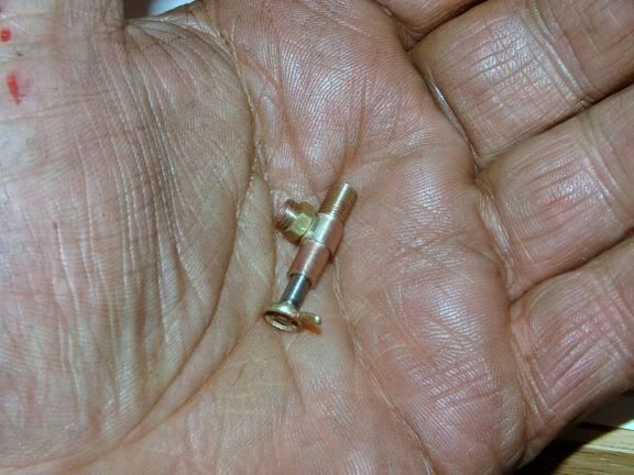
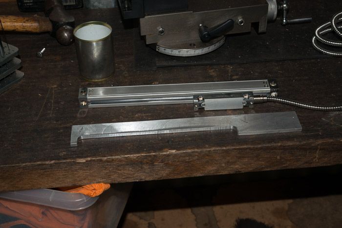
Peter,...For your type of scale mount, I would suggest you go down to the local model shop and get some linkage ball end fittings to connect the quill to the scale, they will get you over the quill rotation problem.John

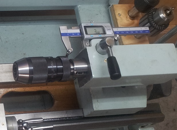
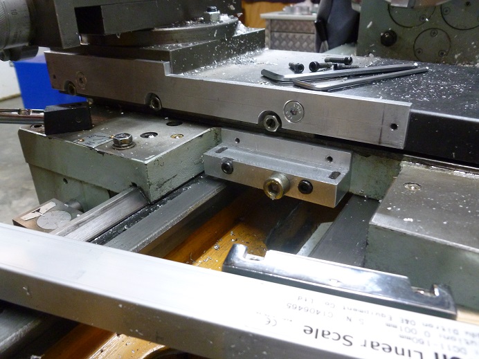
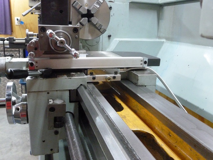
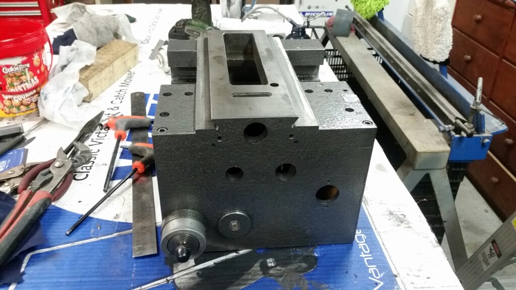
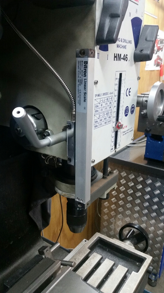
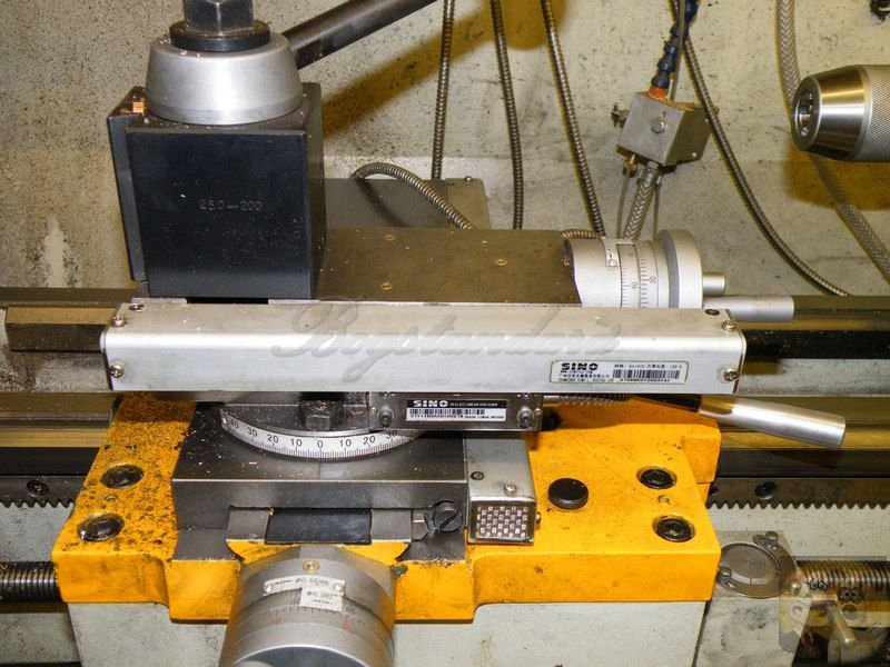
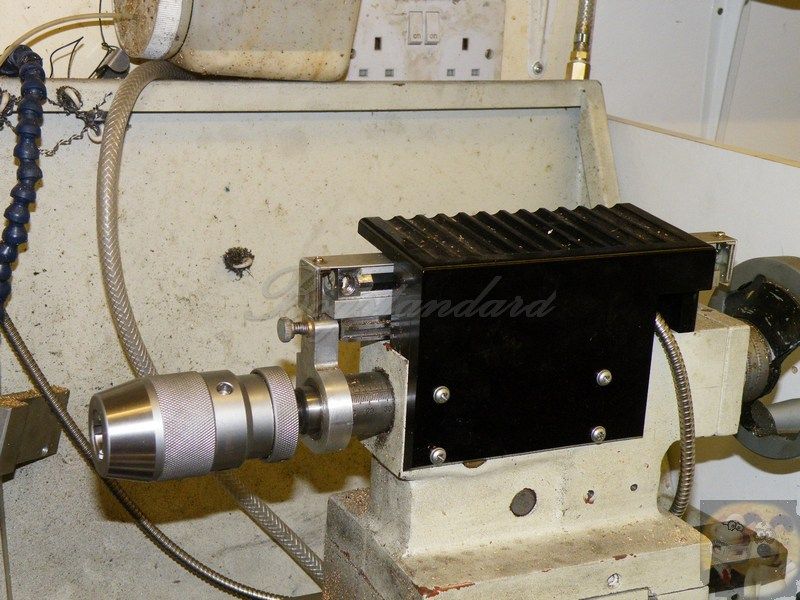
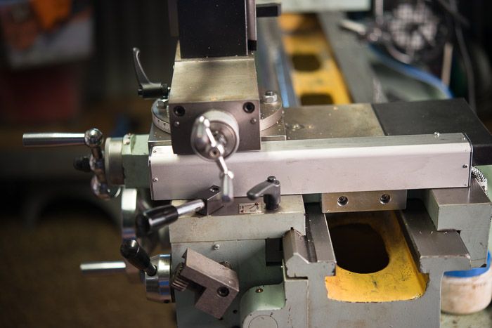
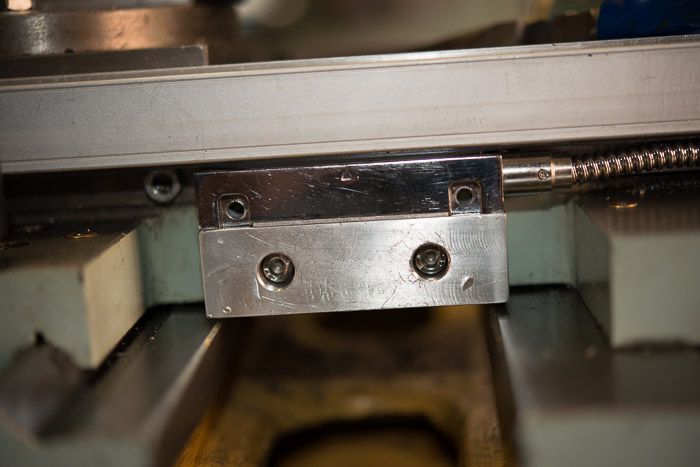
Finally got around to mocking up my bracket. My tailstock casting has kind of a slight tapered crown. But when I make the side ears like so, the DRO/scale is nice & square & visible, doesn't hit the turn wheel etc. The backside vertical plate has 3 threaded holes for bolts to secure it in position set-screw mode for now. I'm not keen on drilling holes quite yet.

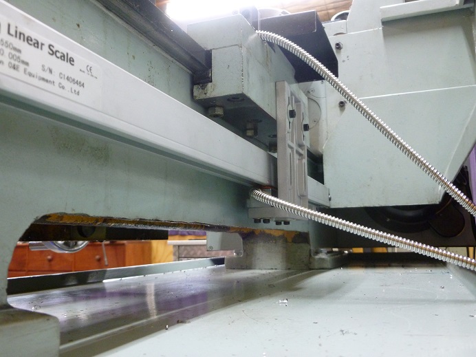
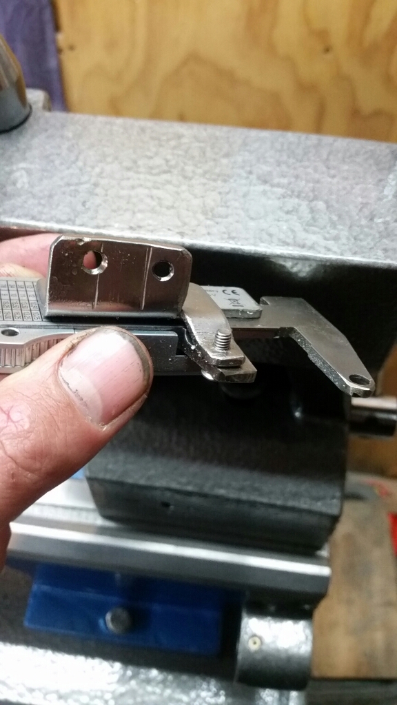
Now the issue I think John is referring to. The barrel has a very slight amount of rotational play, I suspect from the keyway gap. Not a lot but enough that I worry if I mount the DRO assembly firm & to the barrel plate, it will probably impart torque to the extended scale & that cant be good. So yes, I see the need for some sort of 'universal joint'.

I'm totally aware of RC ball links & all their variations. But I'm not quite clear how to mount it. The problem I see is the (ever so slightly) rotating barrel wants to translate this into an extended arc at the mounting bracket. So for example a vertical mount bolt with a ball joint isn't really accommodating this motion? Any clarification or suggestions welcome.

IMG_0600_edited-1.jpg
 
How about a nice fitting pin from the wood into the mounting slot? If the slot is truly perpendicular to the barrel the pin would be able to rotate slightly in either direction without putting any force on the scale. Of course the pin needs to be a nice fit to eliminate any 'backlash' in the scale though. Plus the scale would not be able to rest on the wood so would be unsupported on that end, but I can't see any way around that anyway that wouldn't put force onto the scale.
 
Just went and had a look at my tailstock. Why don't you cut the corner off near the tip of your arrow and place a flexible piece of metal between the scale end and the front mount so it can flex to take up the rotational movement? That way there won't be any backlash. A bit of tin plate or 1.2mm aluminium would do the job. I'm envisaging this plate would be screwed to the mount on the side and the scale stays where it is.
 
Whatever rotational motion due to sloppy keyway will only happen when the drill bit or reamer is under load. If you zero the calliper when there is load you don't have to worry about any accuracy change. You should be able to twist the chuck with one hand and zero the calliper with the other hand as a procedure to take away any error.

I think that the calliper beam can take some twist without ill effect as long as it is well extended.

Just some thoughts to add to the mix. I am still 'old school' and don't have DRO on my machines. For the operations that I do the scales on the machine are accurate enough. Press fit, slip fit and Loctite fit are all part of my play book but not always intentional.

These discussions on adding DRO I find interesting.
 
Old Post but thought I should add my AL320 mods...
My version of a Digital Caliper install, TIG welded a m5 bolt shank onto the front face of the tailstock quill so it can retract fully and eject non-tang tapers. Made an angle shelf and bolted each jaw solid, works brilliant. Did this before I got DRO
20130526_194307.jpg


Like Rodw I researched first and found Ditron on Aliexpress, cannot fault them, excellent product and service. Grabbed a 3 axis because if there was ever a problem I can interchange it with my mill drill DRO, never bothered with compound slide, just went for the 1 micron precision, giving 0.002mm reading on diameter (not that the lathe can do that sort of precision)

Cross slide attachment for DRO 160mm, I added the large cap screw to carriage mount so the tailstock wont hit it
P1000980.JPG


Fitted with small scale, blocks the gib screws but at least its safe from the chuck. I never bothered with the covers...
P1000974.JPG


Simple mounting of long scale
P1000975.JPG


I am currently putting it back together after changing all the bearings for SKF brand and repainting... Here I am matching the carriage to the apron on the shaper... I hated the edges not being flush...
Screenshot_2016-10-18-00-25-19.png


Looks much better in Charcoal Hammertone... probably wont look good for long
2016-10-18%2000.31.57.jpg


Where I am at now...
2016-10-18%2000.32.20.jpg
 
Thanks bob, i was very interested in the tailstock setup. I always figured this was a better way to go than to try and use a 3 axis DRO and fit a huge scale on the tailstock. I have this style on my SX3 mill and I only use it for hole drilling and it is brilliant. Great to see it in action.
 
DJP,

It isn't about zeroing the scale or losing readings at all, it is about the twist imparted to a rigidly mounted scale on the scale's internal runners. They fail badly because of much lesser reasons.

That was why (and I have seen many mods done using this method) I suggested the ball joint solution, it allows the quill to rotate slightly without giving any twist force to the scale. OK you may lose a thou in measurement either way because of the swing of the swivel joint, but at least you won't be doing any damage to the scale.

I went to great lengths to get around that problem when I fitted a proper DRO to my tailstock, and didn't feel satisfied until it had been completely solved, and the way I did it kept my readings spot on.

When you do any modifications like this to a machine, you have to look for any problems that MIGHT occur because of that modification, and being blinkered into thinking it SHOULD be OK as nothing has happened yet is no way to look at it.

It might seem insignificant to yourself as it is only a few bucks worth of scale, but it isn't!!

When you are half way down drilling a critical depth hole, and the scale gives up, that is when the problems usually occur, and that is when it becomes significant.

John
 
I'm finding this discussion very interesting as eventually a DRO on the lathe would be desirable. In the mean time I'll use dial indicators and digital callipers.
Keep the pictures and ideas coming! :thumbup:
 
Thanks rodw :cool:

I think that the calliper beam can take some twist without ill effect as long as it is well extended.
I have found my method to handle rotation twist very well, as it is only pivoting between one bolt per jaw, and to be honest I only notice it when the quill retracts just beyond flush as the jaws close and there is still 0.1/0.2mm more to retract, you see the whole caliper shift, otherwise it has been flawless
2016-10-19%2021.11.03.jpg

Blogwitch said:
DJP, It isn't about zeroing the scale or losing readings at all, it is about the twist imparted to a rigidly mounted scale on the scale's internal runners. They fail badly because of much lesser reasons.
I see DJP mentioning caliper as opposed to scale, calipers are tough... and I never thought much about a scale on the tailstock, just too bulky.
As I have my HM46 quill using a glass scale, and it has rotational twist (passive tho, not load reactive as the quill isn't the spindle) I thought carefully about how to combat it (My first alignment of the lathe cross slide was off and I had very slight read counting errors so I learnt that correct angles also matter), hence some unused mounting holes on the read head bracket.
2016-10-19%2021.20.36.jpg

Instead of hard mounting the scale and making an arm for the read head, I hard mounted the read head to the side of the mill and have the scale move up and down, this has helped, it still has significant rotational twist, but it is not giving me read errors, I may find it failing in the future, but I'll take the risk. Bracketry is minimal and I get to keep my depth stop (which will be upgraded later)
 
J,

In my opinion, fitting DRO's to a model engineering machine has been one of the main steps forwards in home machining in a long time, just like fitting 3phase motors and VFD's to give infinite speed control.

Unlike what a lot of old timers think, it isn't cheating, as all it is doing is superceding earlier mechanical methods of measurement.

I have been using DRO's since the mid 80's when I was working in a model shop making prototype hard disk drives, and without them at that time, it would have been almost impossible to make to the tolerances required by just jigging and fixture holding, you would have to have made a jig or fixture for each machining operation.
You could now do it with just a couple or three datum points from the bolted down piece part.
I just couldn't wait for the model engineering fraternity to catch up.

When I upgraded my mill system to 3 axis, I had a spare 2 axis display head, so it was only logical to fit it onto my lathe, which already had 2 axis on there. This was at a time I was using my shop as a precision machining area, and those two extra displays made all the difference to what could be achieved.
Try to make a hundred of these steam control valves with some internal tolerances of 2 tenths. This was easily done with my lathe DRO's.

valve2.jpg


I suppose eventually four axis will become readily available for mills and lathes, until then, we have to take whatever is available. There are already 4 axis display heads out there. Maybe we can do away with scales on our handwheels eventually, I haven't had to use mine for years.

Four axis on my mill, the small one on top is a display head for the scale type I use on the quill and it doesn't require batteries as it runs from a specially designed PSU that a friend made for me.

flywheel54.jpg


Display heads on my lathe

Mount2.jpg


The two extra bits that aren't normally fitted

Topslide

DRO%205_zps4xxr3g00.jpg


Tailstock

DRO%206_zpss2kdypri.jpg


Please excuse the junk in the background, that is my spraymist system that had to be got out of the way while I did the DRO mods.


John
 
Bobwho,

"I see DJP mentioning caliper as opposed to scale, calipers are tough... and I never thought much about a scale on the tailstock, just too bulky."

I wasn't referring to a glass scale, I was referring to the cheapo SCALES some people fit, which are the same as the digital scales you use for measuring.

When they are put into a stressed situation, like being twisted, they can have a dramatic failure rate. I know this because I spent a small fortune trying to keep them running on my old mill, I had to have a couple of new or repaired scales sitting in my cupboard all the while they were fitted. It was a godsend when I started using glass scales on my then new machines.

Glass scales are no more tolerant, if you can't mount them totally stress free over their whole range of movement, it is not worth bothering trying to fit them.
I have 7 glass scales (soon to be 9) and one cheapo scale fitted to my equipment and I have yet to have one even flicker with discontent purely because I took the time to mount them correctly with absolutely no twist or deviation over their whole length of operation. It takes lots of time and effort to do it like so, but it is time well spent rather the "throw it on there and if it works, it's done" brigade.
As far as I am concerned, it might not be a few months or even a couple of years, but it will show up bad workmanship in the end.

I might be a bit paranoid over things like this, but I do know that of all the machinery in my place since it was upgraded to mainly all new some years ago, none have never failed me, except when it was a manufacturing fault, one bearing failure (10 minute replace job) and one motor failure (new motor sent out for next day).

BTW, on your glass scale fitment, that is where you should have used a slip joint on you bottom fitting as I did on my tailstock fit, it is the only way to rid yourself of the twisting motion while still retaining your measurement accuracy.

John
 
Last edited:
I've fitted a 2 axis DRO to my AL320G. I went with Ditron and am very happy with the quality. The price was pretty ridiculous.

The cross slide was a bit fiddly but worked out nice.

DSC_4730_zpse5bbedca.jpg


DSC_4588_zps1b5c4fb7.jpg


DSC_4740_zps14a431ad.jpg


DSC_4584_zps3914514e.jpg


The long feed was easy, made mounting blocks with a slight angle on them and included a setscrew to level the mounts in case I got the angle wrong. I did not use any of the included mounting hardware.
Rod, new chap here. I also have an Al-320 G- L141 and would like to fit a2 axis DRO. It's like buying milk "too many choices". Anyway after looking at your installation my lathe maybe a bit different as there is oiling points and adjusters on the tailstock side of the cross feed. Was this an issue with your installation ?
Kpar
 
I've fitted a 2 axis DRO to my AL320G. I went with Ditron and am very happy with the quality. The price was pretty ridiculous.

The cross slide was a bit fiddly but worked out nice.

DSC_4730_zpse5bbedca.jpg


DSC_4588_zps1b5c4fb7.jpg


DSC_4740_zps14a431ad.jpg


DSC_4584_zps3914514e.jpg


The long feed was easy, made mounting blocks with a slight angle on them and included a setscrew to level the mounts in case I got the angle wrong. I did not use any of the included mounting hardware.
Not sure what I done before but unable to get my message so will try again.

Rodw, new chap here. I also have an Al-320 G- L141 and would like to fit a2 axis DRO. It's like buying milk "too many choices". Anyway after looking at your installation my lathe maybe a bit different as there is oiling points and adjusters on the tailstock side of the cross feed. Was this an issue with your installation ?
Kpar
 
Kpar,

You raise a very good point about items being under the read head.

When my lathe was new, it was supplied with the read head already fitted and it covered up the gib locking screw, which is definitely required if taking heavy cuts.
Luckily, my lathe has tapered gibs so those didn't come into equation, just the locking screw.

This post shows how I got around the problem, and can be used anywhere a locking device is required on a dovetail slide.

http://chestermachinetools.forumchitchat.com/post/locking-up-my-cross-slide-7284193?pid=1286083315

John
 
Not sure what I done before but unable to get my message so will try again.

Rodw, new chap here. I also have an Al-320 G- L141 and would like to fit a2 axis DRO. It's like buying milk "too many choices". Anyway after looking at your installation my lathe maybe a bit different as there is oiling points and adjusters on the tailstock side of the cross feed. Was this an issue with your installation ?
Kpar

Sorry for ignoring you Kpar, some of us work for a living. Yes I need to remove the cover to get to the oiling points but I watched the placement of everything so i could get to them. Every time I tke the cover off, I think of leaving it off, but its only 2 scews so I pop them back in.
 

Latest posts

Back
Top