Joachim Steinke
Active Member
- Joined
- Jun 14, 2010
- Messages
- 29
- Reaction score
- 22
Today I want to tell you about my latest activities on tool making for my small lathe.
A well and true running live centre is a must have on every lathe, although most of us will not need this accessory every day. And some jobs like miniature camshaft or poppet valve making require a smaller and more slender live centre than the big ones that come with our lathes normally.
And actually there is no real need to build ones own live centre. You can buy special slender models or even complete sets with exchangeable, slender cone inserts for nearly every morse taper size from your industrial suppliers. And for low budgets, the cheaper sets from Vertex can be an acceptable alternative.
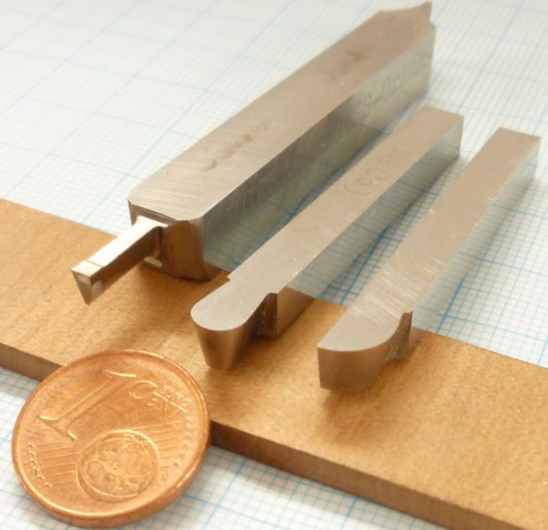
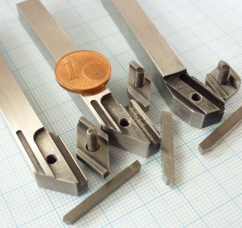
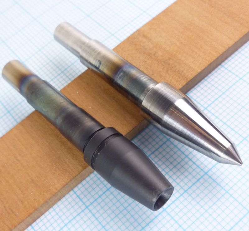
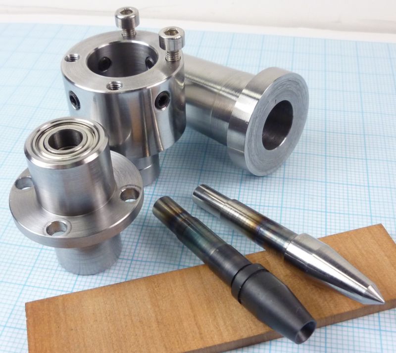
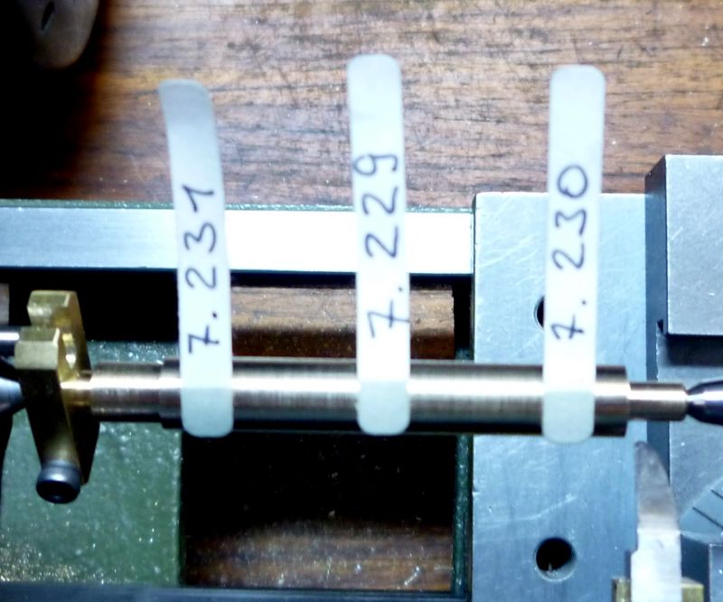
Unfortunately all the commercial sets dont fit for my lathe, my PD360 has a shortened MT2 inside its tailstock. You can realize this on the photo: on the left side and in the middle are two tapers that fit in my tailstock, a normal standard MT is shown on the right side.
And shortening the MT with a saw or grinder is no good idea, the secondary bearings are located directly near the end of the taper, so the whole thing will be definitely damaged afterwards this operation.
Additionally I have a slight misalignment of the tailstock, turning really precise fits, especially at shaft lengths over half an inch, is not possible between centres. To make things worse my tailstock is fixed, there is no sliding base for any adjustment.
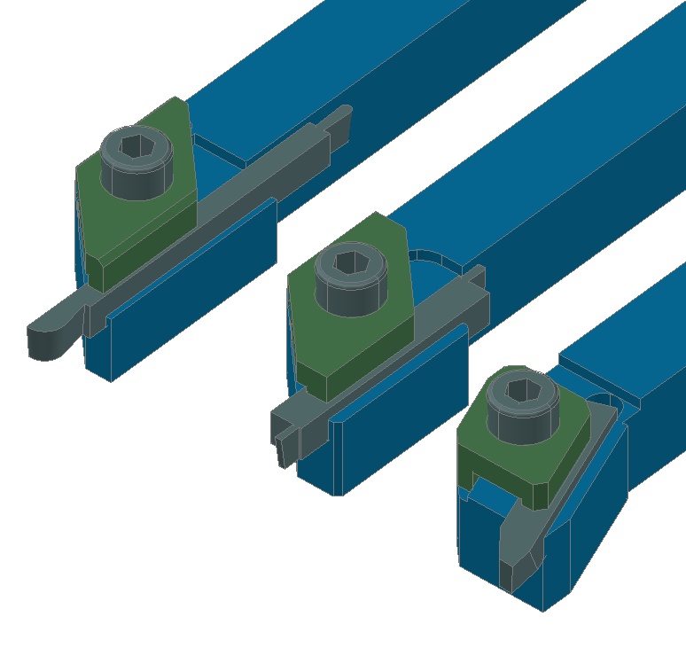
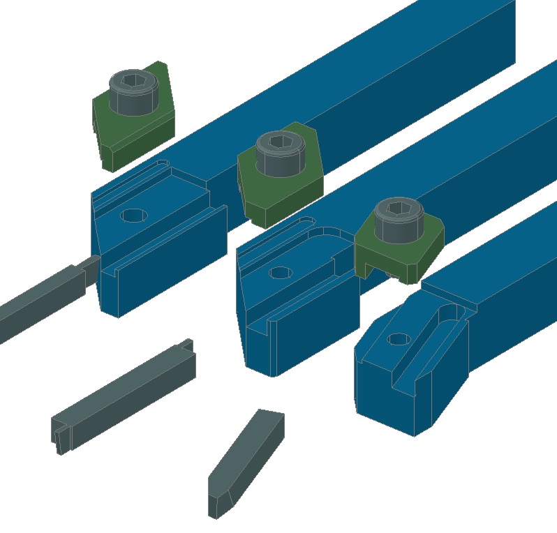
So I had to design and build something that fits in this special short taper and will help me with the misalignment too:
The bearing house is slightly smaller in diameter than the corresponding boring in the main house, so it can be moved a little bit in all directions on its flange plane until it is fixed with the four frontal screws. And to make adjustments easier four headless screws are placed on the circumference.
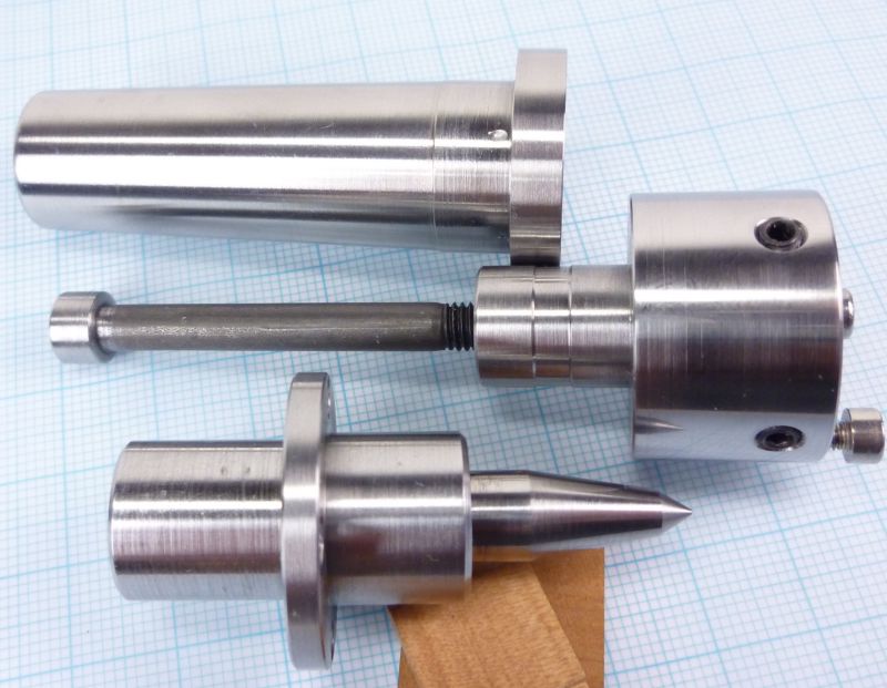
The taper base is a commercial MT2 shaft with a cylindrical front area for self machining fixtures. As the shafts are soft inside you have no problems with drilling and boring until you stay away from the hardened surface zone. But I would have no chance to bring the taps in the surface area, what is the reason for the additional component which connects the MT with the bearing house.
The other components are made of high strength steel and the exchangeable cone tips are from silver steel and then hardened afterwards.
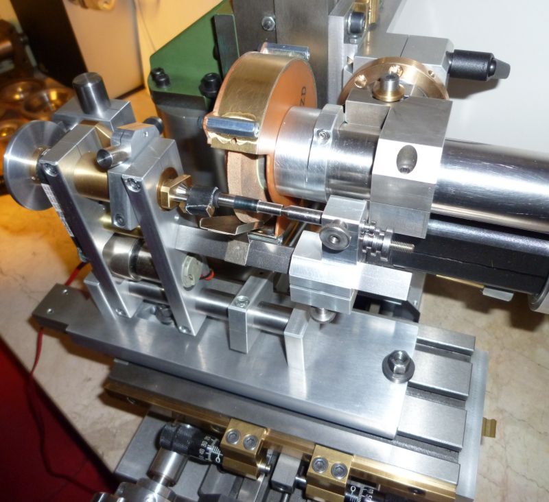
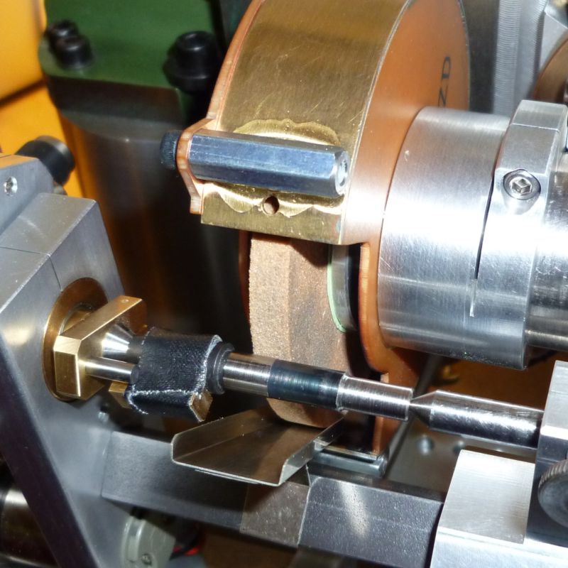
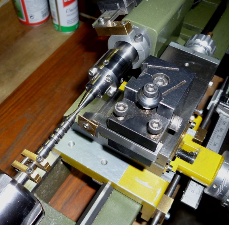
As the cone tips should run as true as possible I had to grind the bearing seats after hardening. I did this on my new cam grinder which can be well used as a cylinder grinder for such small parts.

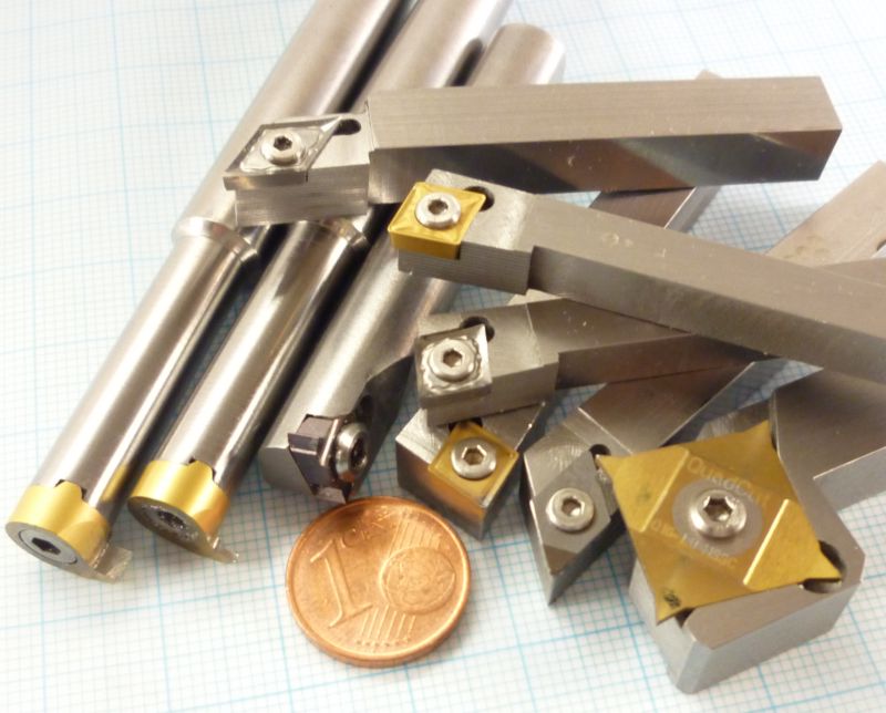
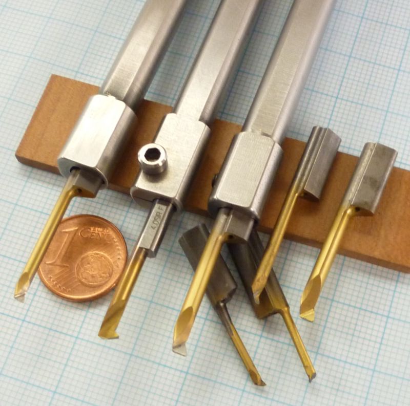
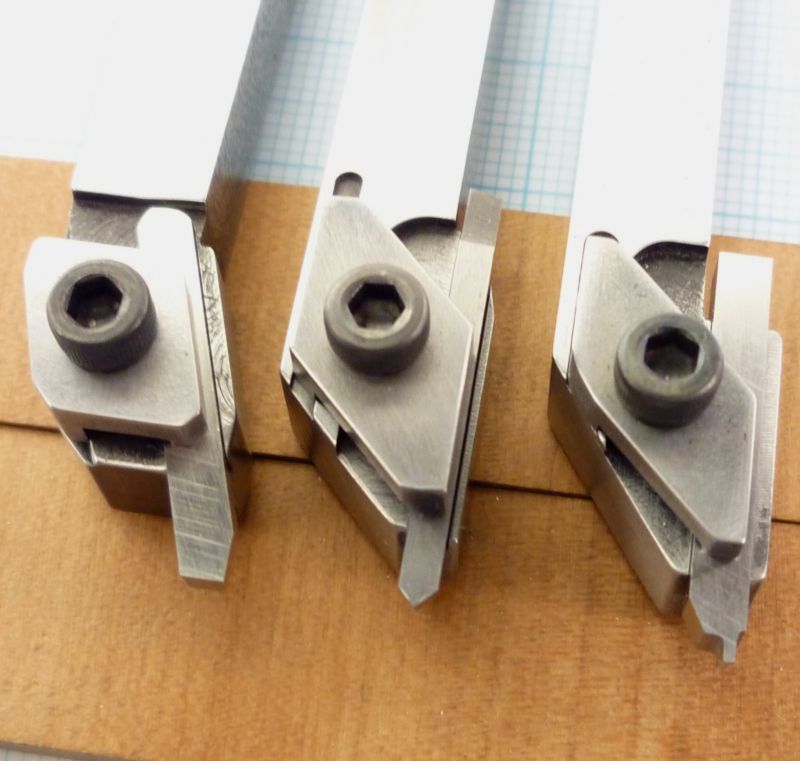
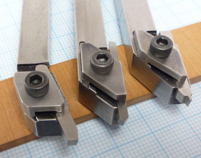
Some pictures of the single components
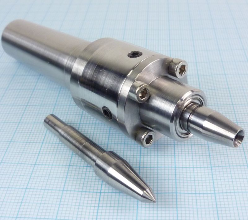
and the complete centre.
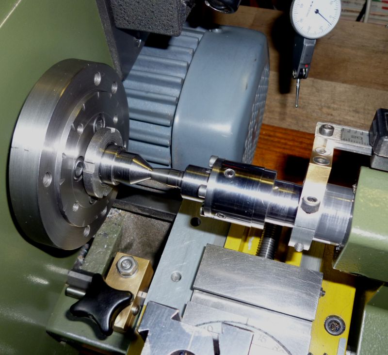
A first rough alignment can be done by pressing the inverted cone insert onto a precise centre located in the main spindle. Afterwards you can tighten the flange screws and set the four adjustment screws on contact to the inner cylinder.
The final alignment was made by turning a testing shaft. After two or three attempts I already managed to fix it well enough.
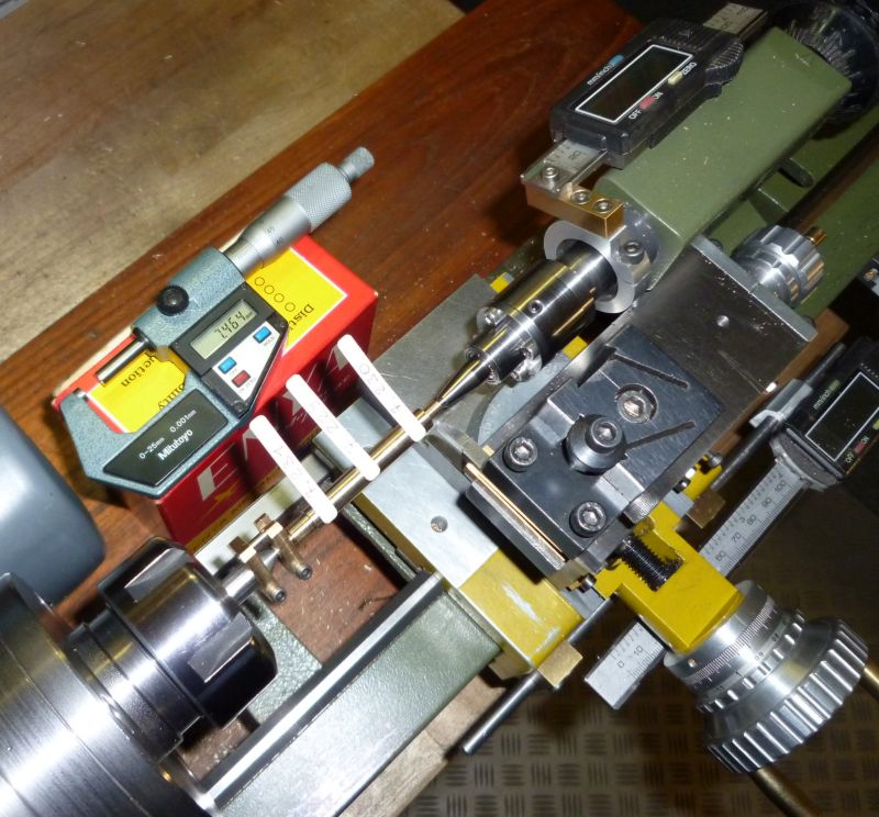
I would say the results speaks for themselves, the last digit of the reading is a thousandth of a millimetre, which is equal to 0.00004in in your dimensions.
Of course the MT will need a small mark at its circumference to reinsert the whole thing precisely at the same position than before, otherwise all the adjustments are in vain.
Finally some pictures of the new centre in use on my lathe. Oh boy, its really nice to have enough working space in front and beside the tool holder at last .ha ha ha .
And turning a well fitting shaft of such small poppet valve would be barely possible without a well aligned tailstock centre.
End of part one
A well and true running live centre is a must have on every lathe, although most of us will not need this accessory every day. And some jobs like miniature camshaft or poppet valve making require a smaller and more slender live centre than the big ones that come with our lathes normally.
And actually there is no real need to build ones own live centre. You can buy special slender models or even complete sets with exchangeable, slender cone inserts for nearly every morse taper size from your industrial suppliers. And for low budgets, the cheaper sets from Vertex can be an acceptable alternative.
Unfortunately all the commercial sets dont fit for my lathe, my PD360 has a shortened MT2 inside its tailstock. You can realize this on the photo: on the left side and in the middle are two tapers that fit in my tailstock, a normal standard MT is shown on the right side.
And shortening the MT with a saw or grinder is no good idea, the secondary bearings are located directly near the end of the taper, so the whole thing will be definitely damaged afterwards this operation.
Additionally I have a slight misalignment of the tailstock, turning really precise fits, especially at shaft lengths over half an inch, is not possible between centres. To make things worse my tailstock is fixed, there is no sliding base for any adjustment.
So I had to design and build something that fits in this special short taper and will help me with the misalignment too:
The bearing house is slightly smaller in diameter than the corresponding boring in the main house, so it can be moved a little bit in all directions on its flange plane until it is fixed with the four frontal screws. And to make adjustments easier four headless screws are placed on the circumference.
The taper base is a commercial MT2 shaft with a cylindrical front area for self machining fixtures. As the shafts are soft inside you have no problems with drilling and boring until you stay away from the hardened surface zone. But I would have no chance to bring the taps in the surface area, what is the reason for the additional component which connects the MT with the bearing house.
The other components are made of high strength steel and the exchangeable cone tips are from silver steel and then hardened afterwards.
As the cone tips should run as true as possible I had to grind the bearing seats after hardening. I did this on my new cam grinder which can be well used as a cylinder grinder for such small parts.
Some pictures of the single components
and the complete centre.
A first rough alignment can be done by pressing the inverted cone insert onto a precise centre located in the main spindle. Afterwards you can tighten the flange screws and set the four adjustment screws on contact to the inner cylinder.
The final alignment was made by turning a testing shaft. After two or three attempts I already managed to fix it well enough.
I would say the results speaks for themselves, the last digit of the reading is a thousandth of a millimetre, which is equal to 0.00004in in your dimensions.
Of course the MT will need a small mark at its circumference to reinsert the whole thing precisely at the same position than before, otherwise all the adjustments are in vain.
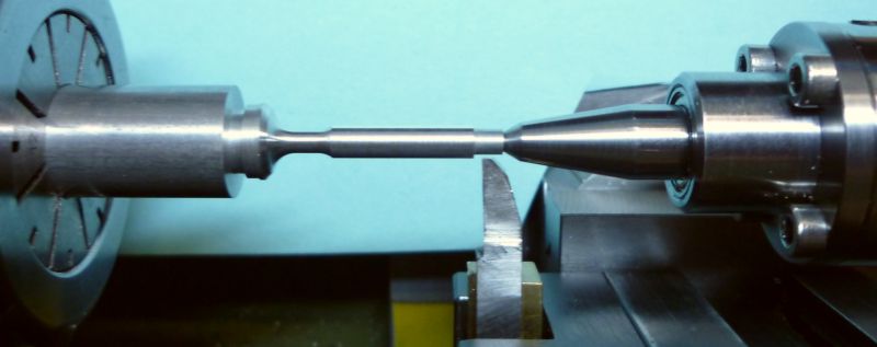
Finally some pictures of the new centre in use on my lathe. Oh boy, its really nice to have enough working space in front and beside the tool holder at last .ha ha ha .
And turning a well fitting shaft of such small poppet valve would be barely possible without a well aligned tailstock centre.
End of part one