a scratch built wobbler steam engine

Home Model Engine Machinist Forum

Help Support Home Model Engine Machinist Forum:

This site may earn a commission from merchant affiliate links, including eBay, Amazon, and others.

toad281

Active Member
Joined
Jan 10, 2021
Messages
25
Reaction score
2
Location
Bainbridge NY
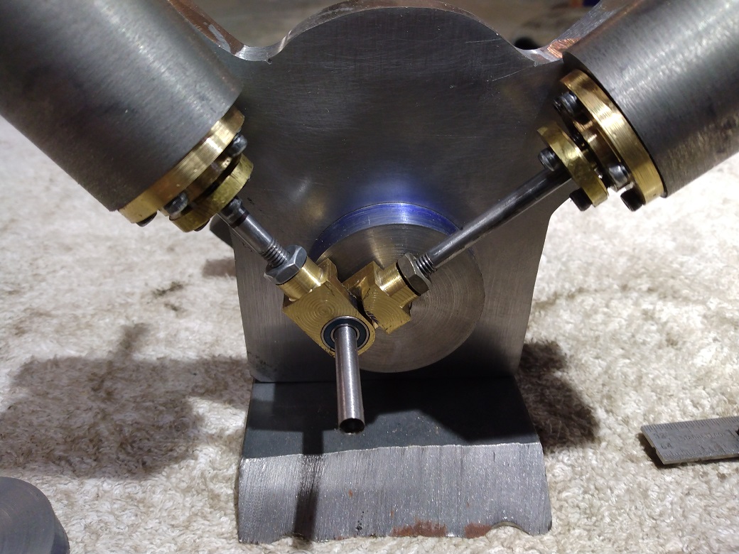
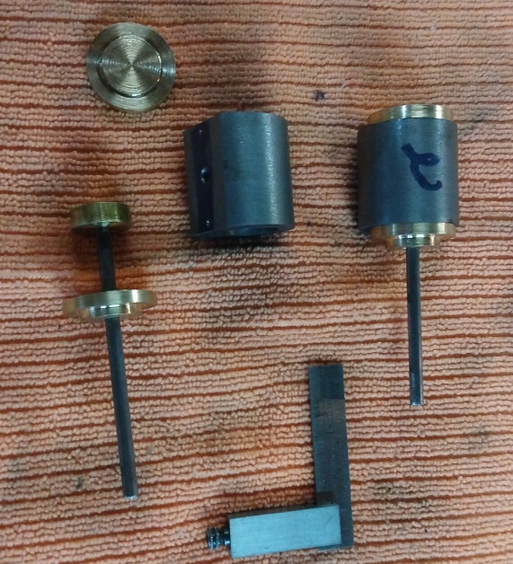
I am in the process of scratch building a two-cylinder, 90Degree "V" steam powered wobbler. The bores are 3/4 inch, and stroke is 1-1/4. Cast iron cylinders, brass pistons, steel frame. I have the cylinders, covers, pistons, connecting rods completed with no known issues. My question relates to the inlet and exhaust ports in the frame. I know how to align them above and below the cylinder pivots, however I am unsure about the lateral positions. As the port in the cylinder makes its arch, at what point along that arch, should the port in the frame align with it? I know the steam should ideally enter a bit before TDC. Is there a placement that relates to the crank? for example; the ports should be in full alignment when the crank is about 5 degrees before TDC. I hope I am making sense to at least some of the experts here.
 
Hi
I am not an expert but I understand your query. I am also starting a scratch build wobbler and when I look at a few published designed I see the ports are in line at TDC and BDC so will make mine similar. I am pretty sure the engine will run with quite a wide tolerance away from the centres and it would be interesting to know what is optimum. It would be nice to build some sort of variable timing but I cannot see an easy way to do that.
 
For the wobblers I've built, I inserted a scribe into the cylinder port and assembled the engine. I then rotated the engine throughout its range of motion and then disassembled the engine.

The scribe then shows where to put in your porting.

...Ved.
 
May I suggest making a flat plate scaled to the size of the cylinder with the inlet hole, pivot hole, and crank pin hole duplicated in the flat plate? You could then rotate your crank to the optimum position for both inlet and exhaust position, and transfer the hole centers onto the steam chest/block. This would give you accurate placement, and you could even work out the EVT theory proposed above as well.

Not my idea, several model builders recommend this practice to establish inlet and exhaust hole positioning on a wobbler.

John W
 
Hi thanks for the all the replies. I have made some progress on the build. After some input from several forums, I did indeed remove the cylinder covers and scribe the position for the ports. For now, I have them the same size as the ports in the cylinder and will enlarge them if needed. The pictures included here were shot about 1 month ago. I have made some more progress and will post updated pictures soon.
 

Attachments

  • steam1small.jpg
    steam1small.jpg
    207.1 KB · Views: 89
  • steam2small.jpg
    steam2small.jpg
    261.5 KB · Views: 90
  • steam3small.jpg
    steam3small.jpg
    232.2 KB · Views: 84
  • 1st small.jpg
    1st small.jpg
    188.3 KB · Views: 84
And here are some more recent pictures. I silver soldered the fitting in today. The last picture is the results of getting too close with the torch. I had to remove and replace that fitting. All is going well so far.
steam4small.jpg
steam5small.jpg
steam6small.jpg
steam6small.jpg
steam8small.jpg
steam8small.jpg
 
A very "sturdy" looking engine, and attractive with the contrasting metal colors. I particularly like the five bolt pattern on the cylinder ends. The usual pattern of six seems so tame, and everybody knows they were just stepped off with a pair of dividers. :)
A REALLY interesting engine is the wobbler designed and built by one of the members using a magnet to hold the cylinder to the frame. This eliminates the often ugly treatment of the spring&screw&nut.
Excellent work, carry on!
 
Well, I have made some slight progress on this build. The piping is all silver soldered, and the reversing valve is in place. I ran it on air yesterday, but did not have a pressure gauge and regulator in the line so I do not know what pressure it was running at. I still have some cleanup, sanding and polishing to do on it as you can see from the enclosed pictures. All in good time. Thanks for all the replies and help.
4-4-12-2022asm.jpg
 

Attachments

  • 4-4-12-2022bsm.jpg
    4-4-12-2022bsm.jpg
    198.9 KB · Views: 37
Terrific looking engine and some fine work here Toad, Have you given any thought to putting your drawings/sketches together and ULing them here? I for one, and am certain many others here, would really enjoy seeing them and perhaps building one on the near future.
 
I would gladly post plans here, but I work without drawings. I can do work from plans, but usually on small, fun build things just kinda wing it. Thanks for the complement. I will hopefully start on the boiler build soon, but I have this cast iron 2-cylinder air compressor head, just mocking me in my workshop. Hmmmm.
 
Back
Top