a different lathe taper attachment?

Home Model Engine Machinist Forum

Help Support Home Model Engine Machinist Forum:

This site may earn a commission from merchant affiliate links, including eBay, Amazon, and others.

petertha

Well-Known Member
HMEM Supporting Member
Joined
Jun 24, 2010
Messages
2,361
Reaction score
931
I have a rather dumb question. At minimum it should give some of you experienced machinists a good chuckle as you enlighten me. :D

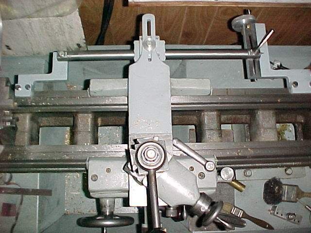
My 14x40 lathe, an older vintage but similar to one shown in the pic, did not come with a taper attachment. I looked into purchasing the attachment through the vendor here in Canada & they were quite fussy about not selling it as an independant unit, claiming it could only be ordered with a new lathe from the outset. I assumed this was just a marketing ploy. They werent too specific other than saying it caused them customer problems in the past so as a policy, didn't offer it. Perhaps there was some legit, specific modifications required of the bed or cross slide mechanism or whatever. I could probably get one out of the States as the lathe design looks pretty standard, but I also found some similar web discussion where others mentioned the same thing or had some difficulties retrofiting their (similar) lathe.

Ideally I'd like to do turn occasional tapers longer than my compound will travel (~3"?)...say 10-12" max. So, onto the question...

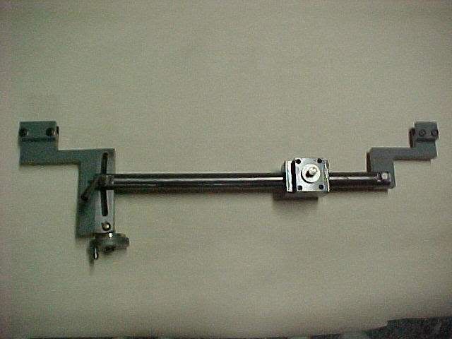
Is there any merit to this idea: Make/buy a dovetail slide similar to the pic, but with a typical turn screw to feed motion & simple bit holding toolpost. Temporarily remove the lathe compound. Replace with the longer slide, set at desired angle & traverse the taper cut just like it was a big compound.

One downside is the ends of a longer new slide may not be in contact (fully supported) by the lathe cross table, but maybe still rigid enough? I dont like the price of that particular slide, but maybe if the concept is ok, I could find something used, or make something comparable, or utilize those dual rod slider assemblies like on homebew CNC's? I would also be foregoing power feed like on a regular taper attachment, but maybe an acceptable tradeoff for less mounting rigamarole & cost? Ultimately it just translates motion to the cross slide anyway. What do you think?


2011-12-01_181835.jpg


2011-12-01_181905.jpg


2011-12-01_182015.jpg
 
You can adjust the tailstock on many lathes to cut shallow tapers........
 
dsquire said:
petertha... here is an excellent article about building your own lathe taper attachment that may give you a few ideas. Don

That is one beautiful attachment he built, for sure! Actually it kind of illustrates my dumb question... all that precision machining work to make a typical taper attachment mechanism: the dovetail slider, the mounting bracketry, the adjustible swivel mechanism, the angle readout... collectively for the purpose of guiding the lathe saddle at desired taper angle (under power feed though, which is nice). But wouldnt 'an oversize compound' using the heart of only the dovetail slider itself accomplish the same thing if all I wanted was a 10" travel?

The nice pics did give me insight into what's required of making a dovetail though. I didnt see where he utilized gib strips (unless I missed it). I wonder how hard it would be to replicate the the specs of a typical lathe compound mechanism? I think I could manage the basic dovetail cuts, but isn't the 'magic' in adjustable gibs & lapping everything into place?
 
vidio1 said:
You can adjust the tailstock on many lathes to cut shallow tapers........

Yes. I've also seen an article somewhere where the ends of the workpiece have a specific counterbore profile to accomodate steel balls (like from bearings) inserted in there to allow higher taper angle cutting & possibly better? workpiece retention. That might be the simpler option I try first.
 
I was thinking about making a taper attachment, because they just don't seem to exist for my machine. I was thinking more along the lines of a linear rail with ball bearing trucks on it instead of dovetail ways.
 
Yes there are all kinds of neat slider combinations out there, some bearings, some bushed on rods...

http://www.pbclinear.com/Gliding-Surface-Technology--Plain-Bearing-Linear-Motion

My hunch is that for a typical taper attachment, some of these could work assuming they run smooth & hold their tolerence. The only force they see is pushing the saddle laterally as it traverses the cut. Thats what originally got me thinking about a simpleton bolt-on oversize compound made from parts like this. But I suspect 'cutting force' in this mode is substantially more. Now its going to torque the whole mechanism, so it probably it needs the classic dovetail configuration (like a lathe compound). Shoulda just bought the dang taper attachment! ;D

 
I know on my lathe the cross-slide leadscrew is different for models with taper attachments. In any case, there needs to be a way to unlock the screw from its nut when using the attachment.
 
I have a taper conversion that looks very similar to the top pictures for my 12x lathe (it was sold that way but would need to be adapted for mine). I've never installed it, but it comes with a new cross slide lead screw and all so it can be disconnected as needed. I suspect these lathes vary so much based on supplier and time that they can't expect a random kit to fit any random lathe.


Here is a picture of the one I made for my Logan 10 x 24. I used a 1" linear bearing because that is what I had on the shelf. If starting from scratch, I would fine a used bar and track of a CNC machine.

I posted the build of this a long time ago so you may be able to find it with a search.

TaperAttachment9.jpg


TaperAttachment10.jpg
 
That is a nice simple design, and likely works well for some work. The deflection in the bar as it moves could be a problem if the accuracy is a real issue, for a TLAR taper it would be fine. On the lathes Ive owned the T/A were designed to be as ridgid as needed to match the capabilties of the machine which they were mounted on. For your own use the light duty type will be just right. The quick change over offered by the factory type T/A, is not needed if you don't care how long it takes to mount and dismount a T/A.
 
Stan said:
Here is a picture of the one I made for my Logan 10 x 24. I used a 1" linear bearing because that is what I had on the shelf.

Is this the original link?
http://www.homemodelenginemachinist.com/index.php?topic=7086.0

When you say linear bearing, do you mean like what I see on hobby cnc machines where the slider block has ball bearings contained in a helical race in the ID? Or is it bushing or lapped type close fit? I like the simplicity of it, thats for sure.

I was kind of wondering about deflection myself. I really dont have a feel for how much force would be imparted from the lathe carriage acting on the bar with reasonable cuts when machining the taper. I read another article where the offset tailstock method was used for cutting the taper & as son as the machine stock got to what looked about 12-16" he had to use a mid point steady rest (I think thats what they are called) attached to the lathe because the workpiece itself was deflecting. I wonder if thats indicative of the same force? Maybe thats why dovetails are seen on commercial units. OTOH, like that link I provided, there are commercial 'double rod' type slider assemblies that might mitigate this.

Apologies for temporarily lifting your picture, but here is kind of what I was trying to express with words. The blue block illustrates the position of an oversize compound travel that would do the taper cutting. The existing, shorter travel compound is just temporarily detached to accomodate. The red block is the toolpost. This way there is no 'translation of motion' issues from a rear mounted taper attachment.

2011-12-03_091243.jpg
 
A very long travel compound could do the job. To me, if you want a decent finish you need powerfeed. That's why a taper attachment is so good at what it does.
 
I would think the oversize compound travel would open you up for some wicked chatter.
 
90LX_Notch said:
I would think the oversize compound travel would open you up for some wicked chatter.

Yeah.. I'm now thinking its a bad idea. The 'more useful' longer travel, the more it is cantilevered it is over the fixed footprint of the carriage base in an unsupported manner. Thanks for the good points everyone.

I cant find the post but the fellow who had my exact lathe mentioned it was also a bit of a headache either disengaging the Y-axis screw, or maybe a different one intended for taper cutting was required. Seems like some lathes do this easy & other, not really. Im not 100% sure. Oh well, I will pursue some offset tailstock centering method. If I ever get another lathe, I think I would get the taper attachment config at the outset.
 
Turning a taper between centers is not difficult at all by offsetting the tailstock.

The link that I posted earlier in is from when I was a newbie at all of this. I had been machining for about four months and made an arbor with two tapers (JT33 and MT1) for my drill chuck.
 
Petertha: Yes, that is my original post on the subject.

The bearing I used is a Thompson pillow block with recirculating balls. It should be used on a hardened and ground shaft but I use a piece of 1" 4140 because I had it.

http://www1.mscdirect.com/eCommerce/SearchServlet/Motion-Control-Fluid-Power/Lin

The pillow blocks are about half way down the page.

On my 10" Logan, I think t would be impossible to make any deflection in the 1" 4140 over an 18" span with cutting tool force. I say impossible because I am not one of the hobby machinists who measure in millionths.

I originally bought several of these used pillow blocks on ebay and had to buy a full length of 4140 from the local steel supplier for a project to build a wheel chair elevator for my wife. The leftover material and pillow blocks have ended up in several projects since.
 
I suppose in theory I could cut a taper the full length of my lathe just by turning the cross slide screw? Of course this is not practical as there is no way I could do that accurately enough, however it would be practical if the cross slide screw was somehow linked to the spindle or the carriage travel.......although I have never heard of one I am fairly confident in predicting that this method has been used on machines in the past.

So, how to do it exactly? Some possibilities....

1. Arrange gearing between the carriage handwheel and the cross slide.

2. Drive the cross slide by a flexible cable geared to the spindle.

3. Drive the cross slide with a stepper motor driven by signals from a spindle encoder divided down to get the desired taper.

The biggest challenge I see is reseting the tool at the start of each pass which would have to be arranged differently depending on which end is the smallest end of the taper.


Latest posts

Back
Top