90 degree joint in rotating shafts

Home Model Engine Machinist Forum

Help Support Home Model Engine Machinist Forum:

This site may earn a commission from merchant affiliate links, including eBay, Amazon, and others.
After a half hour of running in, with the big red beast (My 1/2 HP 1750 rpm bale elevator motor) the wonky joint has loosened up remarkably. The "hard spots" it encounters are right at the point where the sliding sleeve on the main-post is at it's very highest and very lowest points. I think this mechanism would benefit greatly from a decent sized flywheel on either the input or the output shaft. You can see in the picture the almost mirror like finish on the main post where the slider travels. I think a linear ball bushing riding on a hardened, ground, and polished shaft would make this thing almost perfect. I'm not going to do that. For what I want to do with it, it will be just fine the way it is. Since I have yet to make a pulley for it, I may incorporate a flywheel into the pulley.
 
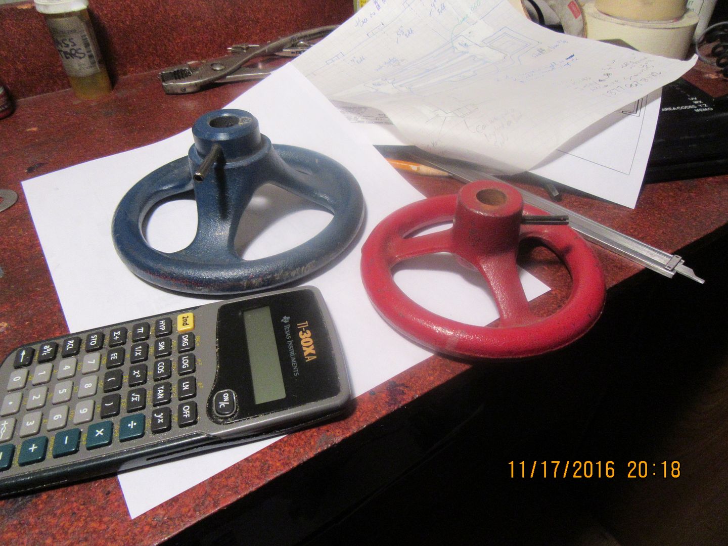
I believe I may have found my flywheel---maybe even my pulley as well. A gentleman from western Canada was in Barrie last summer, visiting relatives. He has been following my build posts for several years now, and wanted to do something to show his appreciation. He brought me an assortment of cast iron valve handles that he thought I might be able to use on one of my "creations". The offset between the center hub and the rim has kept me from using them on one of my engines, but for this project I think they could be perfect.
 
So, as I promised, here is the 90 degree shaft transfer being driven by one of my steam engines. It has been a fun and fast little project, and the transfer mechanism is quite intriguing to see working.---Brian
[ame]https://www.youtube.com/watch?v=c57Hh9E-ovg&feature=youtu.be[/ame]
 
Something neat that I hadn't noticed before---there is a tight spot in the mechanism, just as the sliding sleeve on the main-post reaches the top and starts down again. Watch the way the flyball governor reacts to that tight spot. You can see the balls flying in and out, allowing more air flow into the cylinders as the torque demand increases at that tight spot. It isn't in exact synchronization because of the elasticity of the o-ring drive belt, but it is definitely there. The flyball governor is trying it's best to keep a constant rpm at the engine. Ya got to love that old time motion control action!!!
 
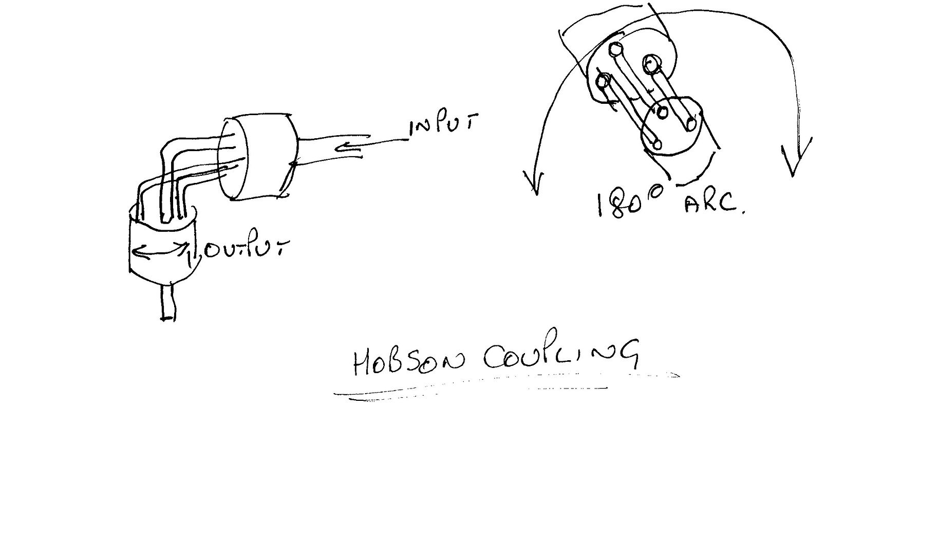
You might try the Hobson coupling, which everyone based their elbow engine designs on.
A very, very rough sketch.

scan0010_zpswqtgvzzh.jpg


It not only can go around corners but the output can swivel through a 180 degree arc with ease if designed correctly.

Imagine the output of this swinging in an arc over the top of the input.

[ame]https://www.youtube.com/watch?v=pVldn35XuXo[/ame]

http://toolmonger.com/2008/05/30/gearless-right-angle-socket-adapter/

I was going to use one of my steam engines to show all sorts of couplings, joints and drives coupled together on one big baseboard, to show to engineering apprentices, but life got in the way.


John
 
Last edited:
So, now that it works, and you all have access to the drawings, it's time to offer up a challenge. Who is going to be the first person to put a third "ear" on that orange colored plate and drive a third shaft of the primary driver (blue) shaft?
 
Back
Top