


mklotz
Well-Known Member
In another thread,
http://www.homemodelenginemachinist.com/index.php?topic=18084.msg187863#msg187863
one of our members, hmember, asked for more detail on the 5C collet divider I made.
Not wishing to hijack the thread, I started this one to pass on some more photos of the device.
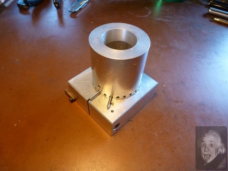
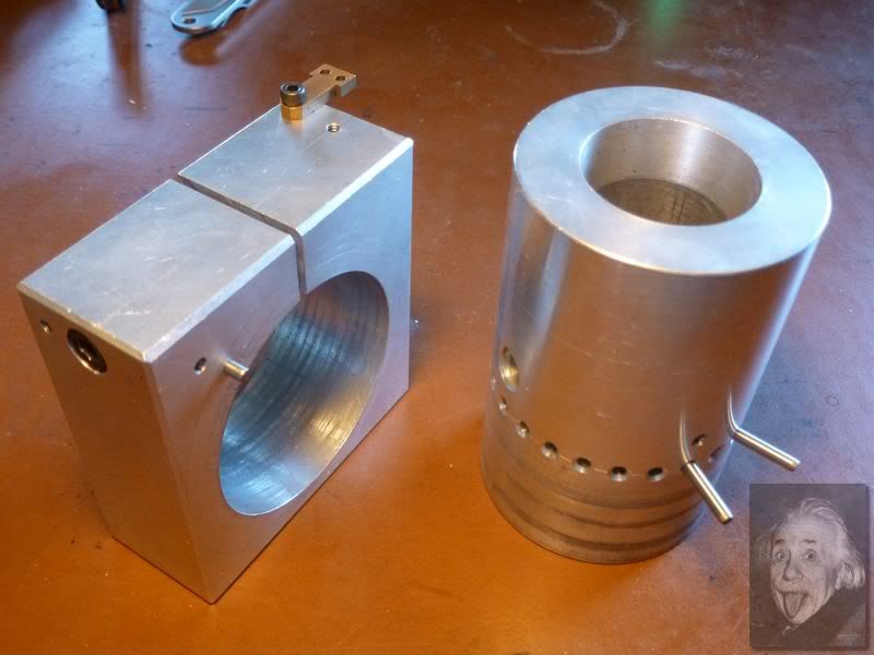
Shown below are the two main components of the device. On the right is the collet chuck which is shaped exactly as one would shape a 5C chuck internally. On the left is the clamp that holds the chuck. It is split and fitted with a SHCS to lock the chuck in place when required. (When the clamp is used in the mill vise the clamping action of the vise closes the clamp and the screw is not required.) The clamp is fitted with a small brass finger stop that allows it to be accurately re-positioned in the mill vise.
The chuck has a dead flat bottom so it will sit vertically in the mill vise. When this flat base is aligned with the clamp base, the 24 indexing holes are just above the top of the clamp and precision pins in the chuck can be used against a pin fixed in the clamp to effect the indexing action.
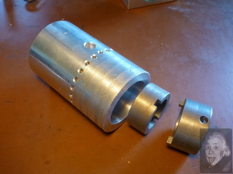
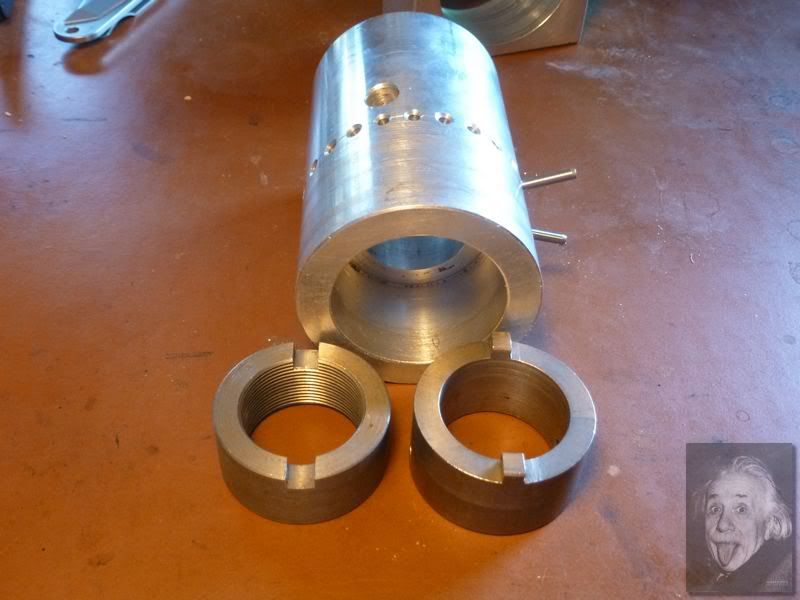
These pictures show the draw-nut used to tighten the collet and the spanner used to tighten the draw-nut. When the nut is fully tightened on the collet in use it's completely hidden up inside the recess turned in the base of the chuck. This is done so the chuck can sit flat when used vertically.
Since the draw-nut is hidden when tightened, a special spanner is needed to reach up into the recess to tighten/loosen the nut. The one shown will do that. It has holes for tommy bars to provide the torque to activate the nut.
This strange cylindrical spanner shape accommodates the situation where the collet is used horizontally on a long piece of stock that projects out of the back of the collet. The spanner is slipped over the projecting stock, its "teeth" engage the slots in the nut, and the tommy bars activate the nut.
http://www.homemodelenginemachinist.com/index.php?topic=18084.msg187863#msg187863
one of our members, hmember, asked for more detail on the 5C collet divider I made.
Not wishing to hijack the thread, I started this one to pass on some more photos of the device.
Shown below are the two main components of the device. On the right is the collet chuck which is shaped exactly as one would shape a 5C chuck internally. On the left is the clamp that holds the chuck. It is split and fitted with a SHCS to lock the chuck in place when required. (When the clamp is used in the mill vise the clamping action of the vise closes the clamp and the screw is not required.) The clamp is fitted with a small brass finger stop that allows it to be accurately re-positioned in the mill vise.
The chuck has a dead flat bottom so it will sit vertically in the mill vise. When this flat base is aligned with the clamp base, the 24 indexing holes are just above the top of the clamp and precision pins in the chuck can be used against a pin fixed in the clamp to effect the indexing action.
These pictures show the draw-nut used to tighten the collet and the spanner used to tighten the draw-nut. When the nut is fully tightened on the collet in use it's completely hidden up inside the recess turned in the base of the chuck. This is done so the chuck can sit flat when used vertically.
Since the draw-nut is hidden when tightened, a special spanner is needed to reach up into the recess to tighten/loosen the nut. The one shown will do that. It has holes for tommy bars to provide the torque to activate the nut.
This strange cylindrical spanner shape accommodates the situation where the collet is used horizontally on a long piece of stock that projects out of the back of the collet. The spanner is slipped over the projecting stock, its "teeth" engage the slots in the nut, and the tommy bars activate the nut.