4 CYLINDER VERTICAL OSCILLATOR

Home Model Engine Machinist Forum

Help Support Home Model Engine Machinist Forum:

This site may earn a commission from merchant affiliate links, including eBay, Amazon, and others.

Richard Hed

Well-Known Member
Joined
Nov 23, 2018
Messages
2,381
Reaction score
616
Location
Moses Lake in the Great Soviet of Washington
Presently I am drawing up J. De Waal's 4 cylinder vertical oscillator, project #09A-14-00. I thot I would very much like to build such a device until I started drawing the cylinder system. My objections are that the cylinder wall is too thin, that it is soldered to a "base" to oscillate together; that the cylinder tops and bottoms are bolted together with 3 long bolts with triangle heads; and that a large air space exists at the top and bottom of the stroke.

I very much like the basic idea of this design, that is, I like the base system with the crank and columns, it's just the cylinder system that I thimk is bad. Can anyone offer some comments?
 
What's the problem with the cylinder wall thickness? I've done larger bore engines with the same wall thickness.

If you don't like the way the cylinders go together then design them differently, could be done from a solid block with end plates fitted in a number of ways, but the triangular cylinder end covers and long studs are a bit of a feature of the engine and stop it looking like all the rest.
Yes, that's true, it certainly doesn't look like all the rest, that's really just a minor problem. The thickness of the cylinder wall just seems too thin to me. As long as the pressure doesn't go too high, it is not a problem. The soldered parts, however, seem WAY too wrong. I thimk a solid piece would be better. What about the air space? This certainly doesn't seem right, or is there something I am missing?
 
Hi Richard, can you share an image or drawing to look at? just had a quick search on google as a 4 cylinder oscillating engine sounds wonderful. Best regards, Nigel
 
Hi Richard, can you share an image or drawing to look at? just had a quick search on google as a 4 cylinder oscillating engine sounds wonderful. Best regards, Nigel
I thimk there is no copyright problem as J. De Waal has put it into general usage with the usual terms: no selling, making them for one's own use, so I'll attach it. I want to make this, but I thimk I will re-design the cylinder section some what. I really like the way the "port block" is made and placed on the side like that. Also, I thimk there must be a better way to hold the cylinders in rather than those springs.
 

Attachments

  • 4-cylindres-oscillant-en-ligne.pdf
    2.5 MB · Views: 148
All of the engines Julius draws up are intended to be built from barstock and not require castings so you will find a lot of instances where parts are fabricated and others where they are cut from solid, that former often saves on material as you could end up producing a lot of swarf if cutting from solid. It's no different to soldering the valve block onto that horizontal you posted about the other day but you did not feel that was wrong?

A simple alteration to the end covers replacing the shallow recess with a spigot that fits into the cylinder would reduce the airspace but unless the engine is going to be expected to do actual work on steam it won't hake a lot of difference.

The cylinder will lift off the port face long before you ever get to a pressure that will burst the cylinder and to burst it would need a lot more pressure than you are likely to get with steam. The spring is far weaker than the cylinder wall so if pressure got high the spring would just allow the cylinder to move away from the valve face and the excess would escape, even if it did not the 0.5mm wall thickness copper tube feeding the cylinders would fail before the 1mm cylinder. You need to study and understand how these engines work before saying peoples work is wrong.

Direct link to the engine on julius' website http://www.vapeuretmodelesavapeur.com/telechargements4/4-cylindres-oscillant-en-ligne.pdf
 
Last edited:
Please tell me what is "Wrong" with these

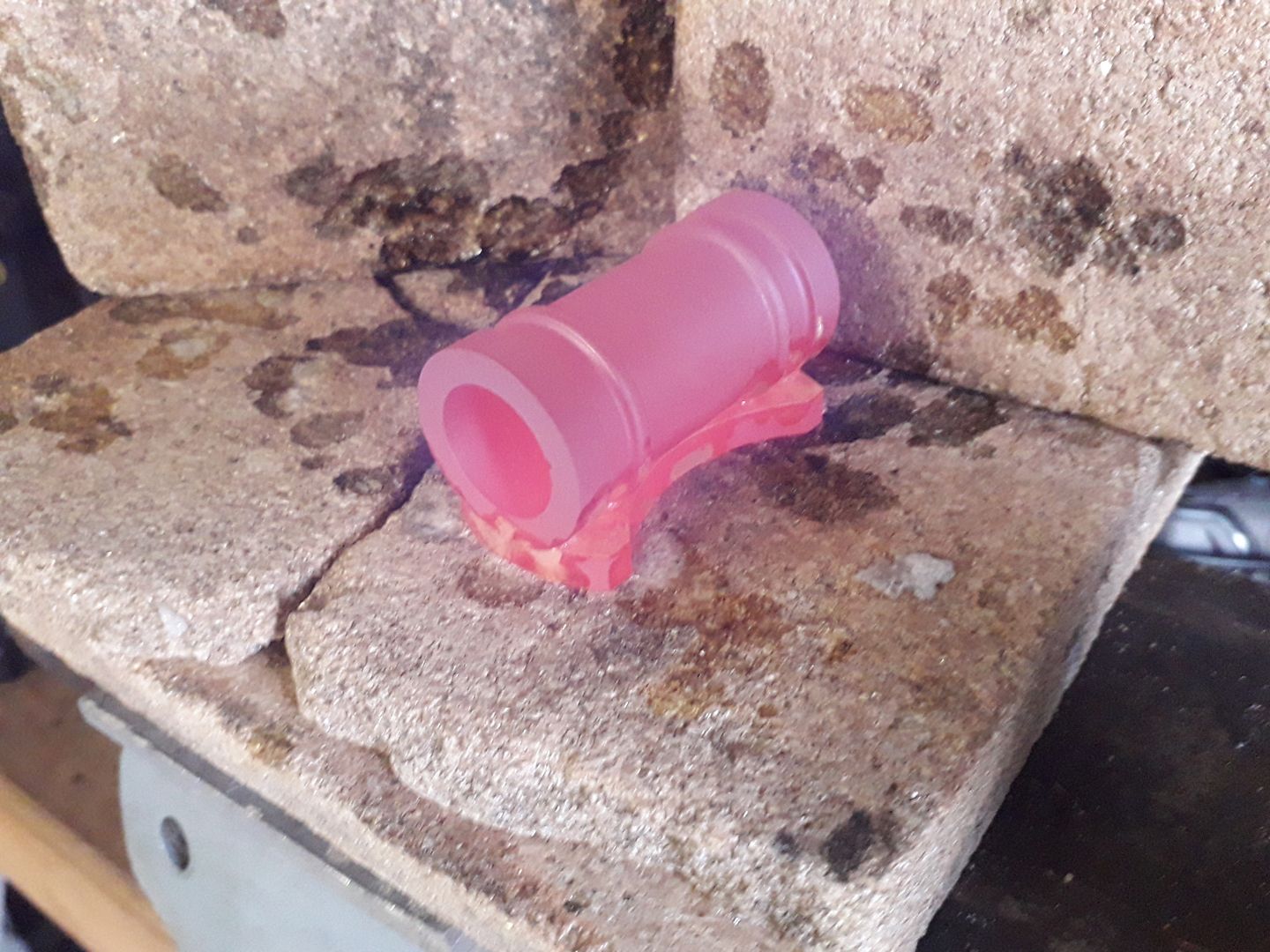
Here is the cylinder of an oscillator being soldered to it's port face

20191227_150522_zpsrkqvdnvb.jpg


And the engine running


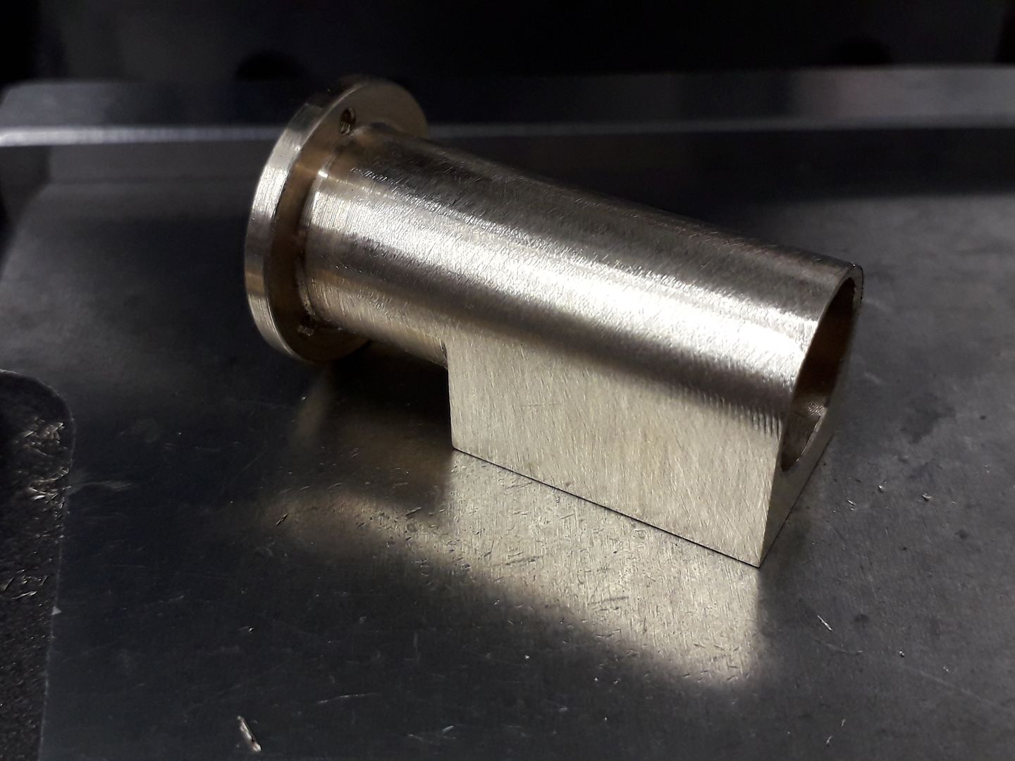
Here is a 12mm bore x 14mm OD oscillating engine cylinder so same 1mm wall thickness

20200226_182827_zpsh70qjsm8.jpg


Same engine running


Those are wonderful. I'm just a silly goose, that's why I am asking these fooish questions. Thanx.
 
An interesting engine, it's worth looking at a mamod engine as they have a thin wall cylinder - I always thought they were soldered, but looking at the images online they appear to be machined from solid
 
Look also at the design from a WigWag or the Wobler
The cilinder is made out of alu stock !
 
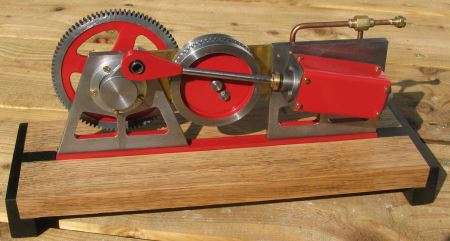
That's interesting, my large oscillating engine is running a cast iron cylinder against mild steel

osc-019.jpg
 
That's interesting, my large oscillating engine is running a cast iron cylinder against mild steel

osc-019.jpg
I have about 150 drawings that I am re-drawing. It takes anywhere from 1 day to about 3 days max. But I don't recall seeing a drawing like that motor. Do you have a movie of this running? I would really enjoy seeing the other side.

I was thimking that iron and steel should be fine against each other, but if not, I was trying to thimk how one might put a bronze or brass sheet between them if necessary
 
Last edited:
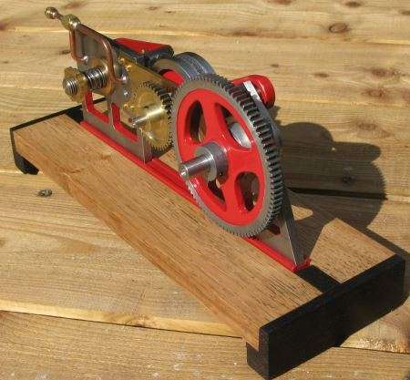
This is the other side. I geared the flywheel up with extracting the last bit of energy from the exhaust gases by impinging them on a toothed feature in the rim.

osc-021.jpg


This is a video of it running before I did the finishing touches


This engine also ran in a slightly earlier guise with a large flywheel and without the gearing


more images and details are on my gallery pages
 
Jason is correct in that the dimensions are well inside of parameters in terms of rigidity and strength. In looking at this design, I am rather drawn (bad pun) to the tricot shaped end caps and can envision some nice fixture work that would simplify their making. He is also correct in his statement of attempting to understand what is being looked at before questioning its design. Of course on this note, you are sketching the drawings out yourself to try and get a better understanding of the workings which is a good thing. May I suggest, choose one of these engines that you would feel comfortable in making, and begin machining it. Choose one that is not overly complicated but would still challenge ones skill sets. Something a bit more than drilling and tapping holes and merely cutting squares and rounds to length. In doing so, you would gain a tremendous amount of understanding and confidence that could be carried over to the second engine, and so forth. There will be failures to be sure, but that is how we learn what we can and can not do within the confines of materials and tools available. And quite a bit can be done with just the basics. Ruler, protractor, dividers, etc. Carry on soldier....

BC1
Jim
 
Look also at the design from a WigWag or the Wobler
The cilinder is made out of alu stock !
I've not seen WigWag before, but this is a lovely looking engine and the plans are very clear
 
I have about 150 drawings that I am re-drawing. It takes anywhere from 1 day to about 3 days max. But I don't recall seeing a drawing like that motor. Do you have a movie of this running? I would really enjoy seeing the other side.

I was thimking that iron and steel should be fine against each other, but if not, I was trying to thimk how one might put a bronze or brass sheet between them if necessary
WigWag V-Twin

This is the link to mine design, enjoy greetings Ronn
 
Hi Richard,
hope you look better than your picture ! LOL
Yes indeed, I already have all the components, meaning stock materials
Now I'm extracting the parts out of the original A3 drawing and put them in a 3D configuration, with FreeCad, so I have them all in a technical drawing !
Then I can manufactor them in my workshop, and hope for a good result
I have the nessesary equipments and tools
Hope I explain this in the right way, because my English is not so good !!
If you will, I keep you up to date with this project ?!
grts Ronn
 

Latest posts

Back
Top