


I posted up the plans for this engine quite a while ago, with the promise that chips would begin flying in September. Well, they did. Things have been moving kind of fast and I can only work on the parts two nights a week for about 2 hours each night.
So far, its all starting to somehow come together. I haven't taken many pictures, and this build will probably not be very well documented, but I'll do what I can and answer any questions.
What I have done so far is the following:
Engine block is about 90% done, needs the camshaft bore and crankshaft bore done. Holding out on the crankshaft bore as I may move to a multipart crank and use ball bearings.
Pistons are about 90% done, ground down to right size and have ringland cut, need to be parted from stock and have pocket cut out for connecting rod.
The head is roughed out and has the clearance holes for the headbolts drilled. Still needs the combustion chamber, spark plug holes, and coolant passages done.
Here is some pictures of the engine block in it's almost finished state (this was taken before the cylinders were honed, it's also coated in oil to prevent rusting.)
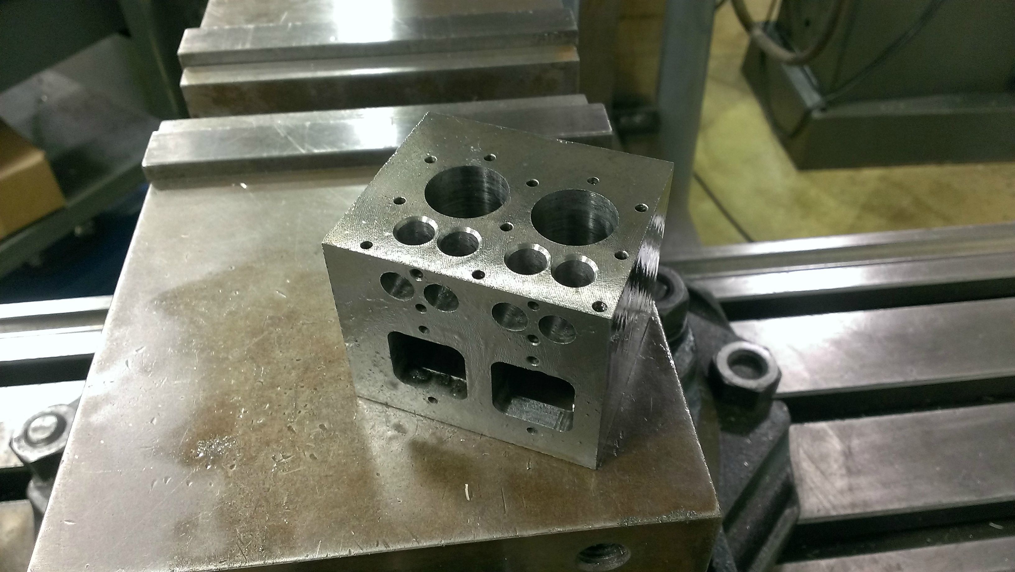
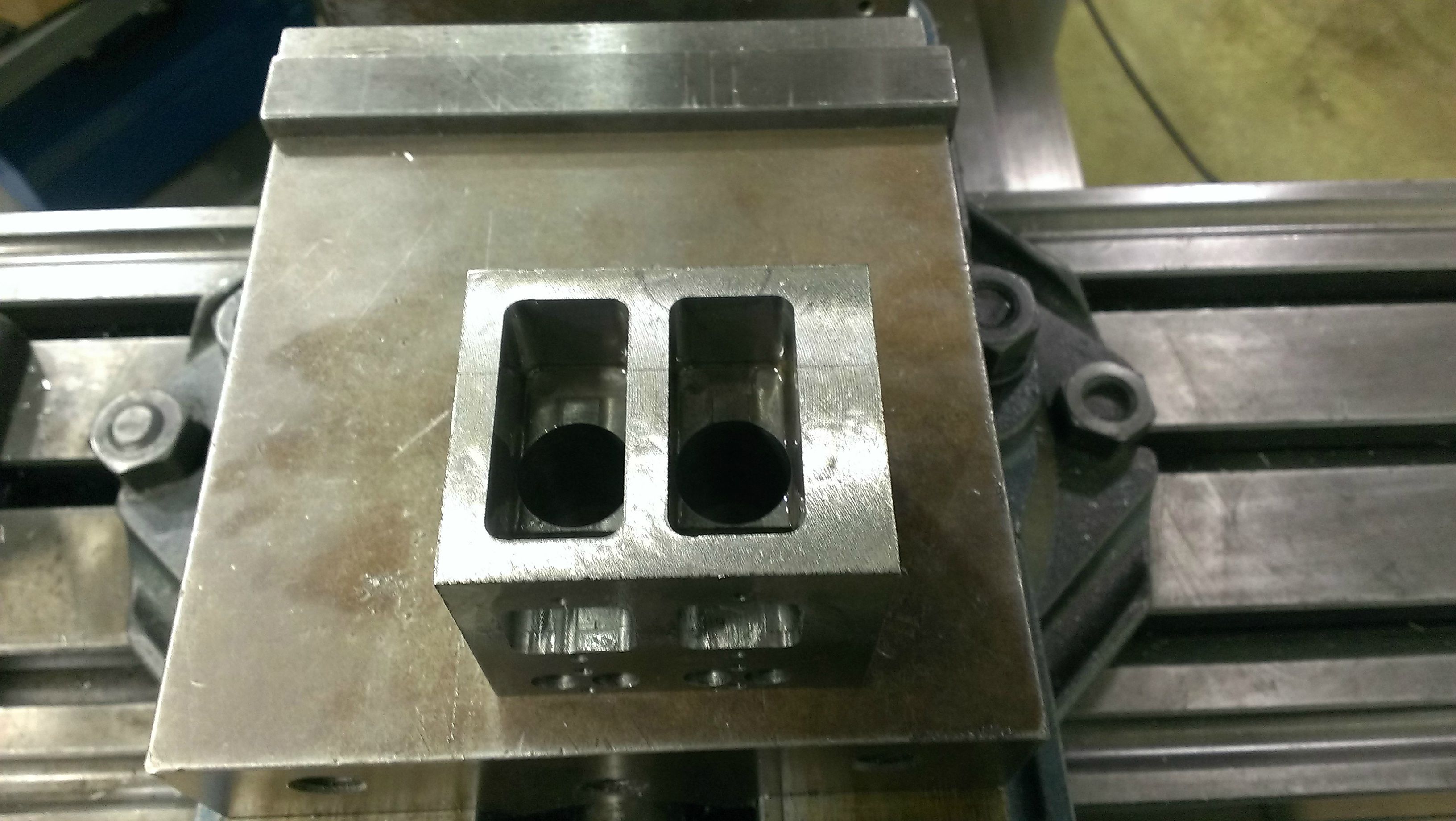
The block was roughed out to the dimensions of 2.4995" L X 2.080" H X 2.080" W. The finished dimensions will be 2.25" L X 2.075" H X 2.075" W. The material I used was Durabar grey cast iron and the stuff seems to machine like butter, as you would expect with cast iron.
The locating of all the features was done on a Haas tool-room CNC mill with a edgefinder and a calculator, then hand jogging the tool into place. The cylinder bores were plunge cut with a brand spankin' new 3/4" center cutting end mill. A slow, accurate feed rate made a very nice finish and the bore is near as makes no difference .750". It was then honed out using a brake cylinder hone to .752". All fasteners on the engine block are 5-40 thread.
The pockets for the crankshaft and valve cage were done by using a 3/4" endmill to rough them out in one plunge cut. It was then mounted in a manual mill and finished out with a 1/4 endmill.
EDIT:
I would also like to add that pursuing this project has made me reconsider my major at college, and am considering changing my major to Machine Tool Automation or CNC Machining.
So far, its all starting to somehow come together. I haven't taken many pictures, and this build will probably not be very well documented, but I'll do what I can and answer any questions.
What I have done so far is the following:
Engine block is about 90% done, needs the camshaft bore and crankshaft bore done. Holding out on the crankshaft bore as I may move to a multipart crank and use ball bearings.
Pistons are about 90% done, ground down to right size and have ringland cut, need to be parted from stock and have pocket cut out for connecting rod.
The head is roughed out and has the clearance holes for the headbolts drilled. Still needs the combustion chamber, spark plug holes, and coolant passages done.
Here is some pictures of the engine block in it's almost finished state (this was taken before the cylinders were honed, it's also coated in oil to prevent rusting.)
The block was roughed out to the dimensions of 2.4995" L X 2.080" H X 2.080" W. The finished dimensions will be 2.25" L X 2.075" H X 2.075" W. The material I used was Durabar grey cast iron and the stuff seems to machine like butter, as you would expect with cast iron.
The locating of all the features was done on a Haas tool-room CNC mill with a edgefinder and a calculator, then hand jogging the tool into place. The cylinder bores were plunge cut with a brand spankin' new 3/4" center cutting end mill. A slow, accurate feed rate made a very nice finish and the bore is near as makes no difference .750". It was then honed out using a brake cylinder hone to .752". All fasteners on the engine block are 5-40 thread.
The pockets for the crankshaft and valve cage were done by using a 3/4" endmill to rough them out in one plunge cut. It was then mounted in a manual mill and finished out with a 1/4 endmill.
EDIT:
I would also like to add that pursuing this project has made me reconsider my major at college, and am considering changing my major to Machine Tool Automation or CNC Machining.