1/3rd scale 5hp Galloway Build

Home Model Engine Machinist Forum

Help Support Home Model Engine Machinist Forum:

This site may earn a commission from merchant affiliate links, including eBay, Amazon, and others.

Jasonb

Project of the Month Winner!!!
Project of the Month Winner
Joined
Mar 30, 2008
Messages
3,786
Reaction score
1,266
Location
Surrey, UK
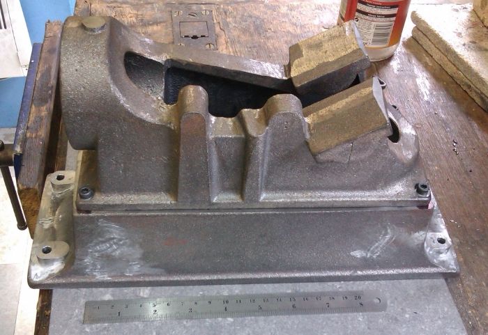
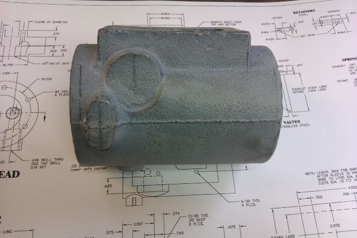
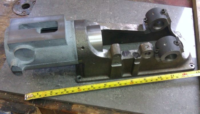
The model is of the 5hp Galloway round rod hit and miss engine to 1/3rd scale so its quite a big old lump.

Galloway-Photo-07_zps332c1eff.jpg


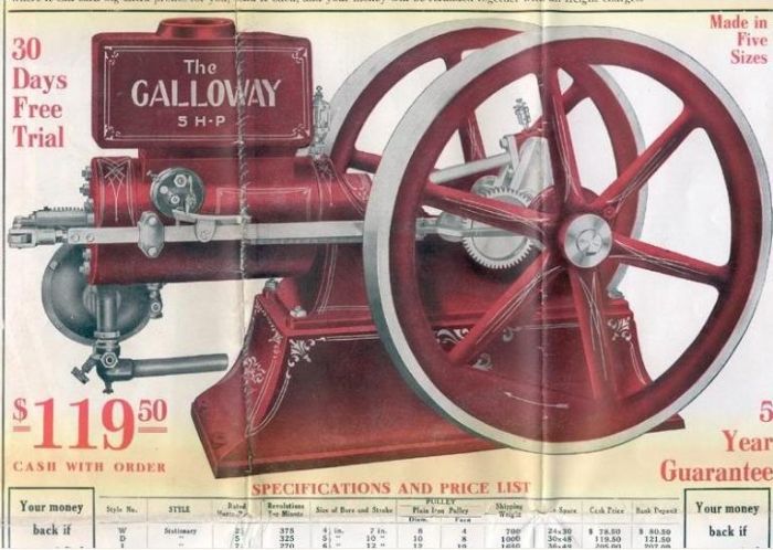
Originally made by Richard Shelley the Galloway kits are now done by
Linley Machine under the Minicastings range and are available in a number of different scales. You can also get them via Forrest Classics in the UK.

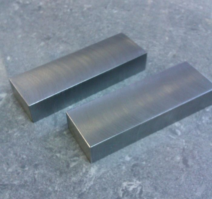
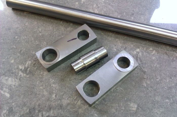
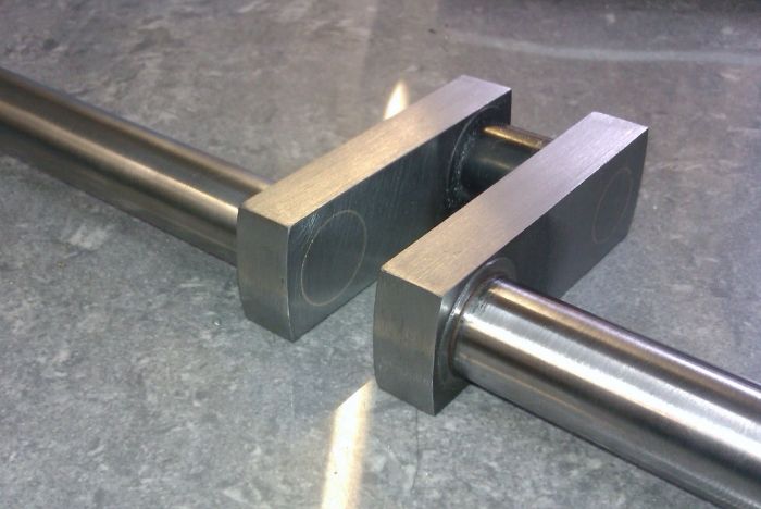
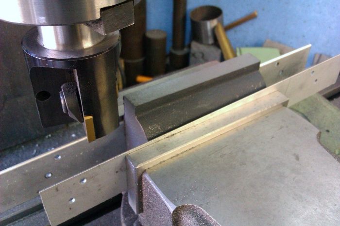
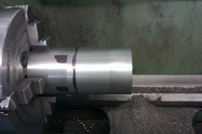
So lets start at the bottom. The kit is supplied with a sub-base and on the larger scale castings the four mounting lugs have to be added as it makes it easier to cast the base without them. These started off as a length of 5/8" hot rolled.

IMAG1532_zpsa132c640.jpg


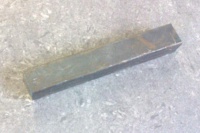
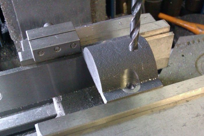
These were cleaned up all round with a fly cutter, cut and milled to length and a hole drilled through each.

IMAG1533_zps105645e5.jpg


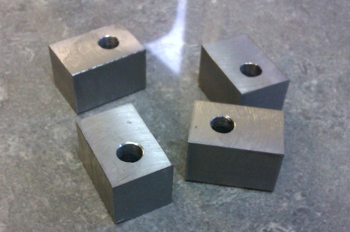
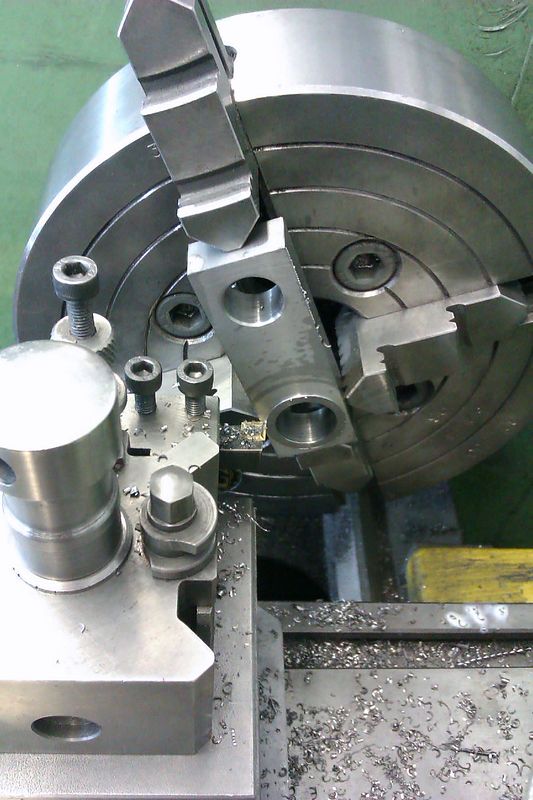
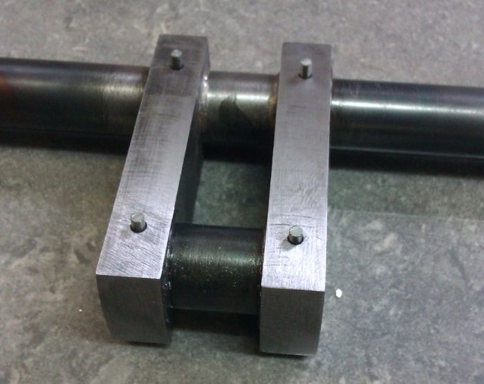
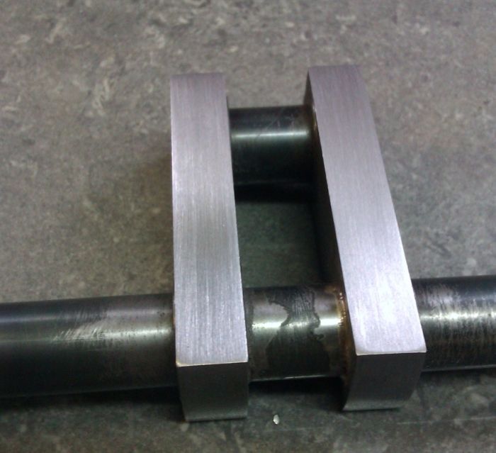
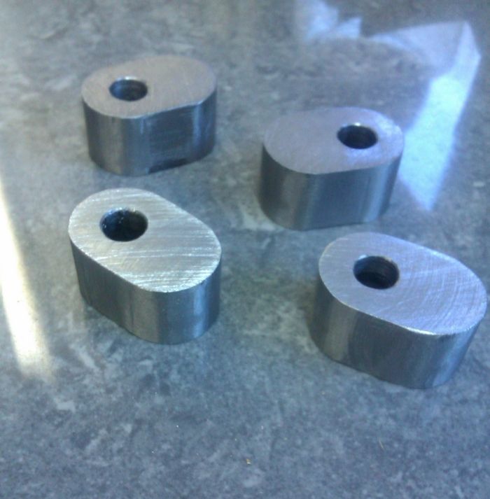
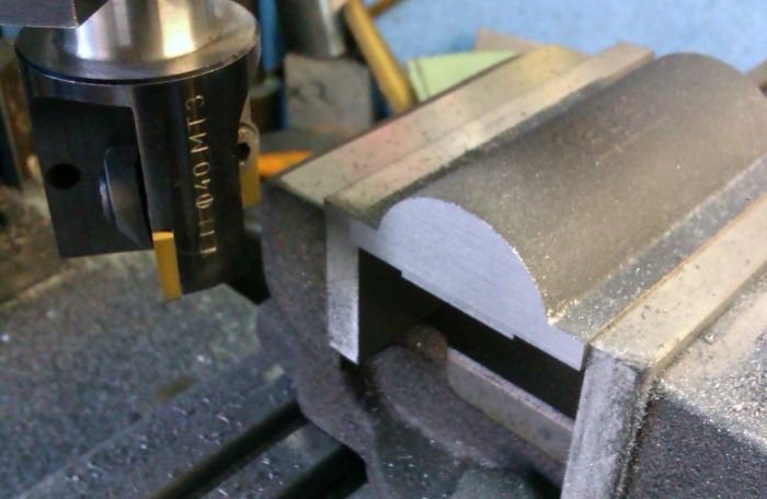
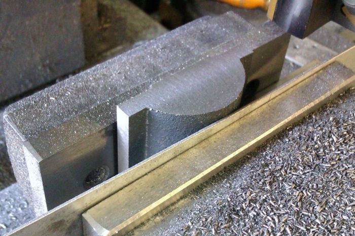
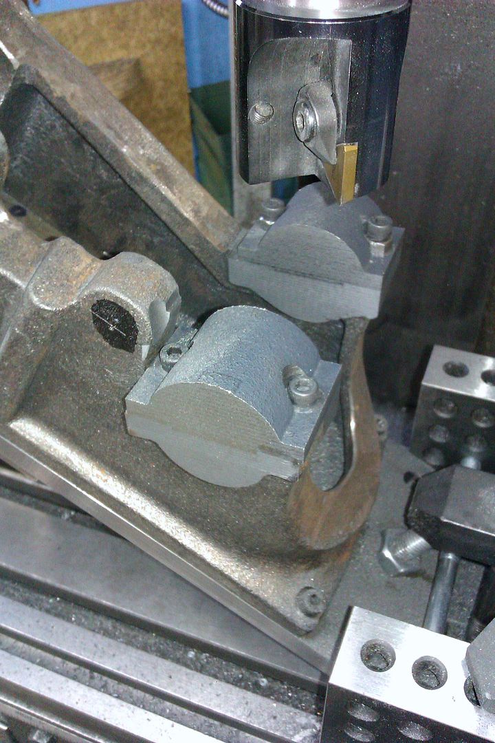
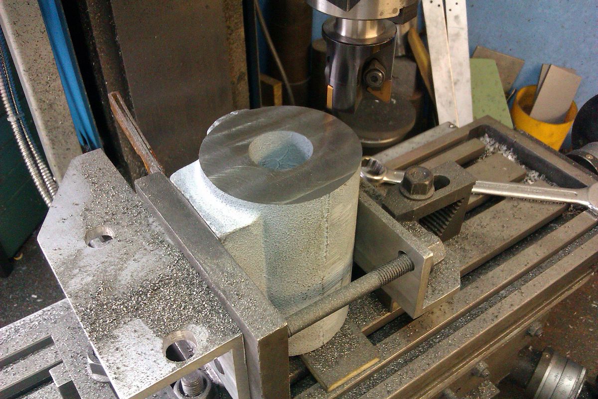
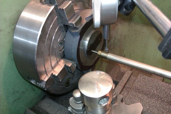
I then set up the vice on top of the rotary table with a stop and rounded the two ends.

IMAG1536_zps969f03b7.jpg


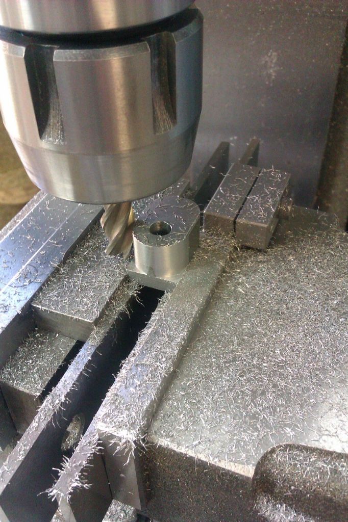
The last job was to machine these to the correct height which got rid of the piece that was in the vice and therfore not rounded off.

IMAG1537_zps809094c7.jpg


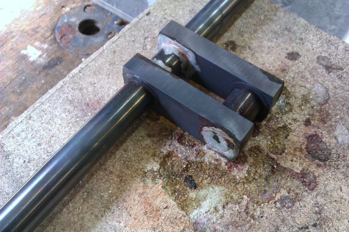
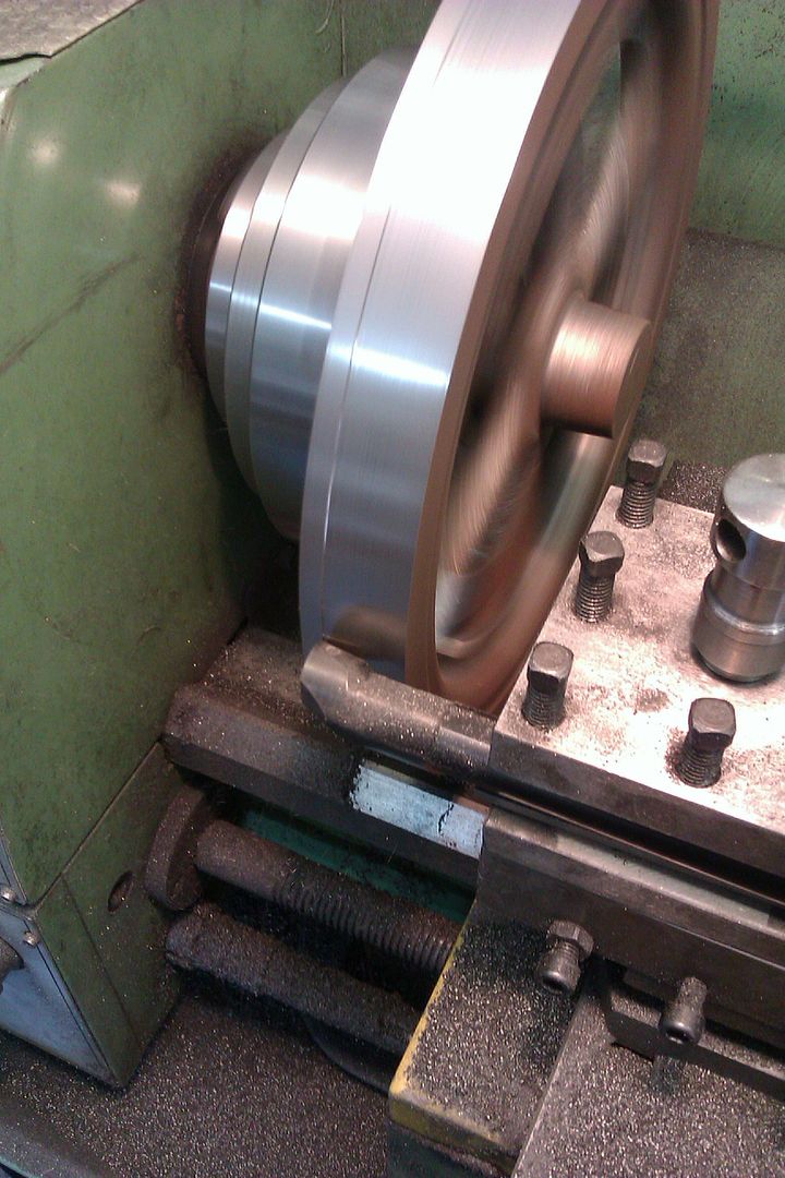
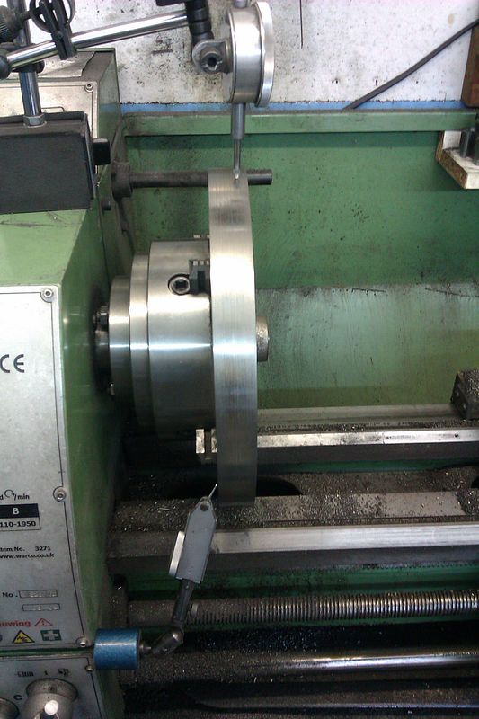
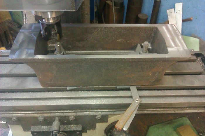
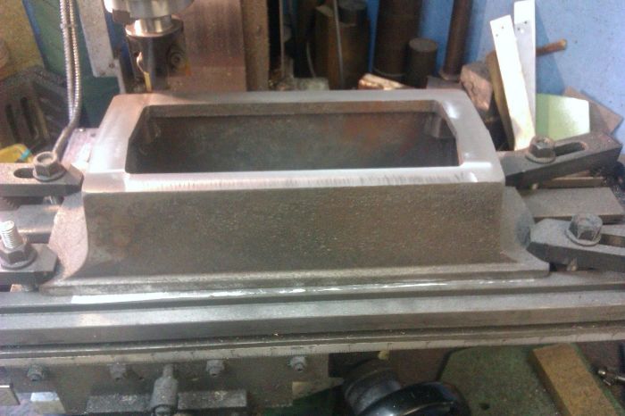
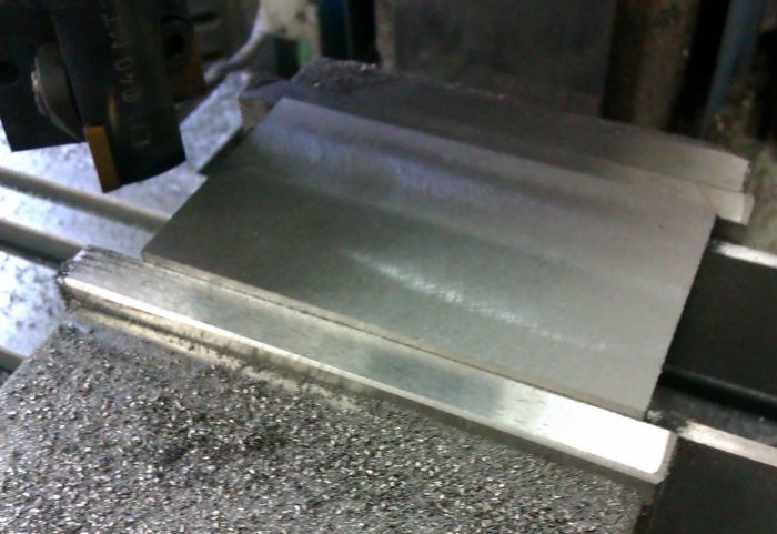
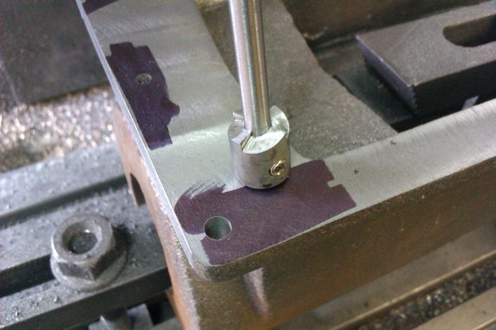
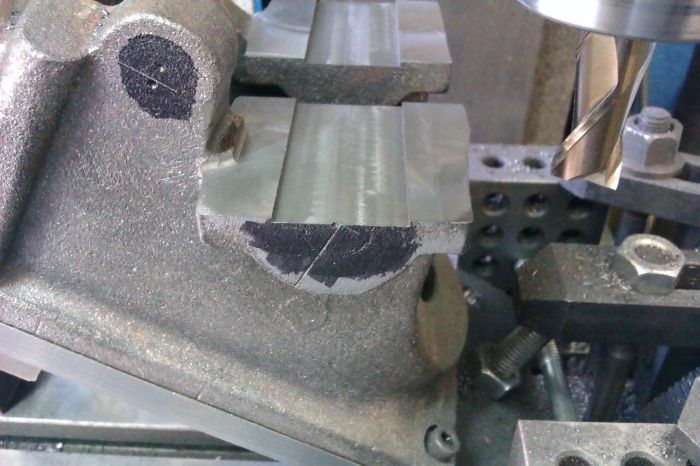
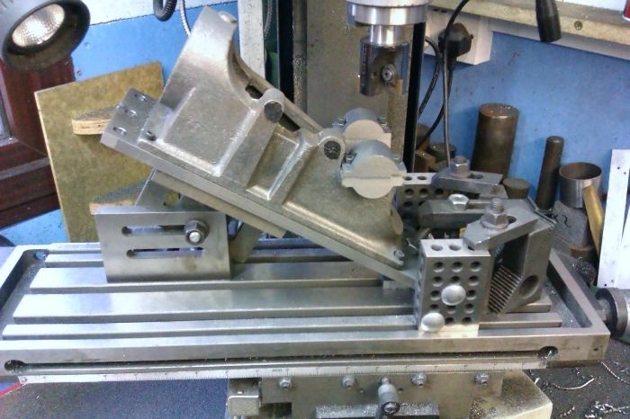
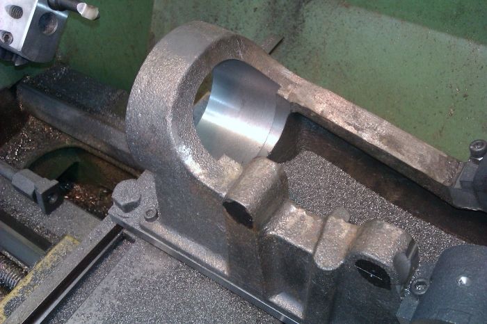
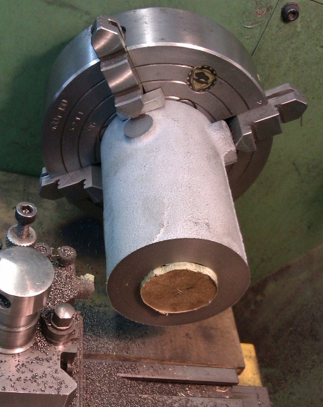
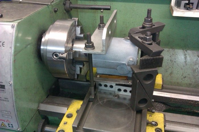
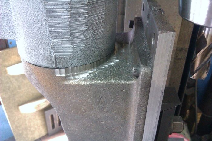
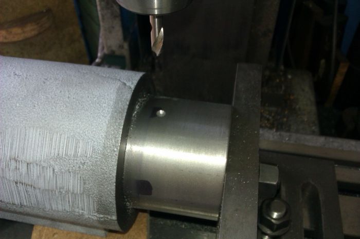
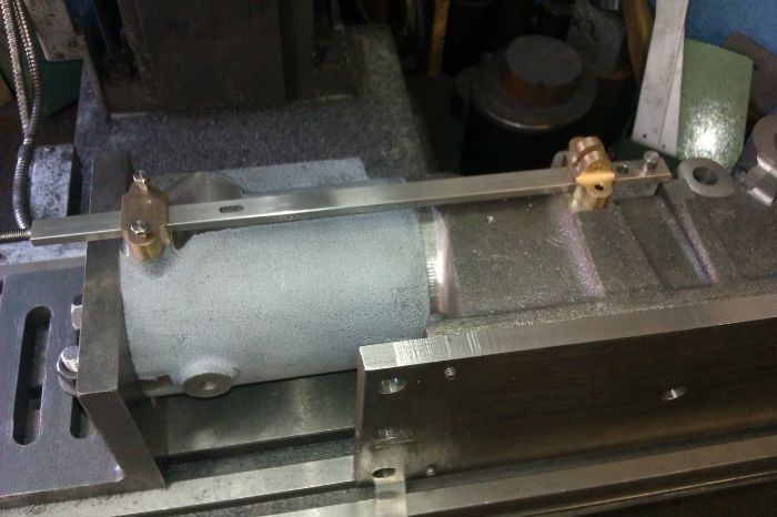
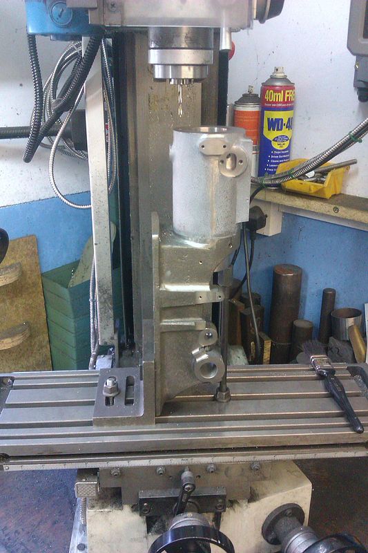
I then spent some time shimming up the base with packers and feeler gauges to ensure that when the underside was machined it would sit true when turned upright

IMAG1566_zps5768b210.jpg


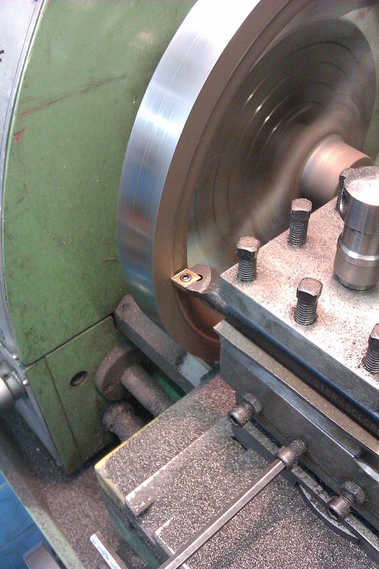
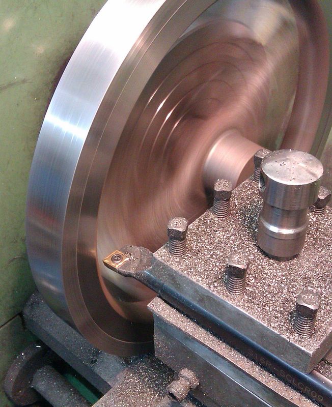
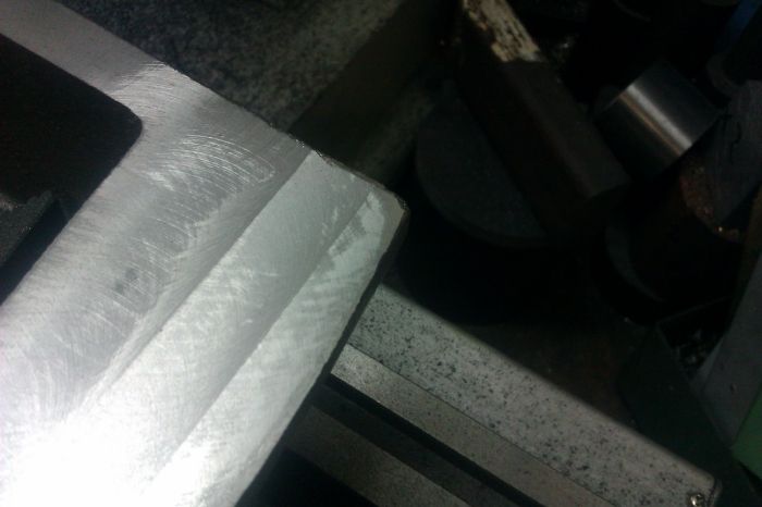
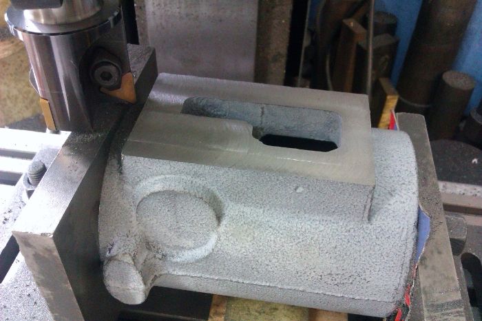
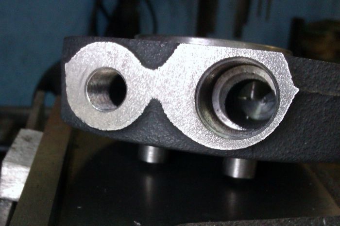
You may be able to see a darker shiny area in the corner, this is where the thin extremities of the casting have cooled quickly and "chilled" the iron, luckily I was using a carbide tipped cutter as these hard chilled spots will take the edge straight off HSS tooling.

IMAG1567_zps22953ab2.jpg


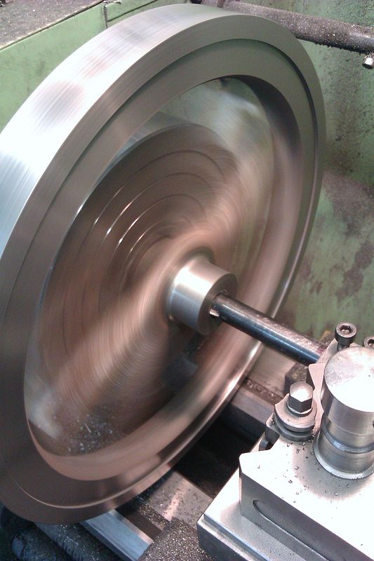
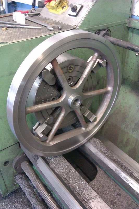
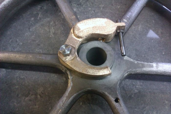
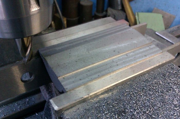
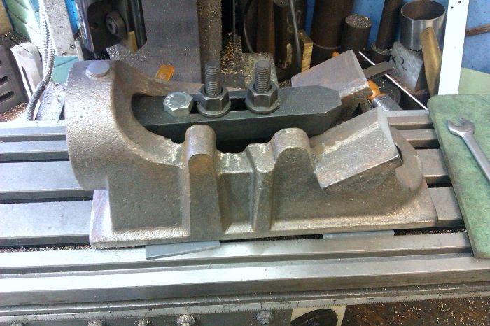
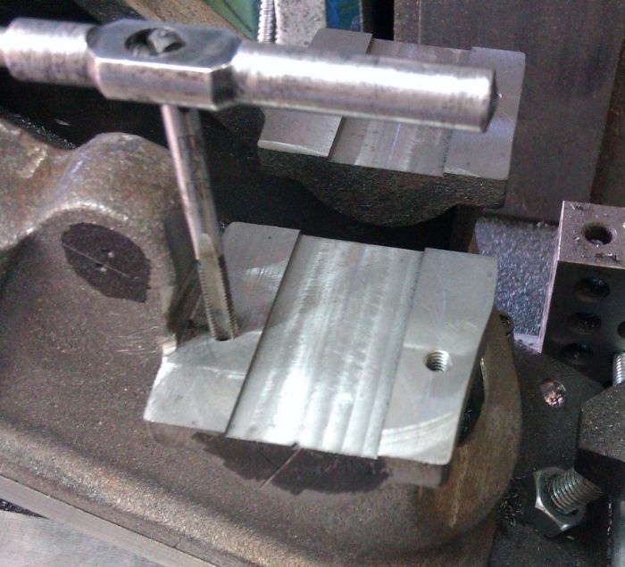
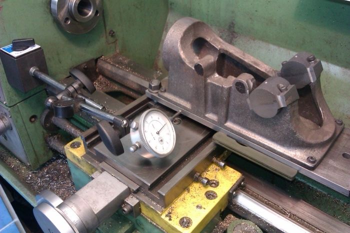
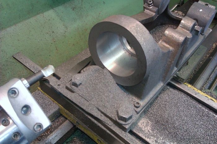
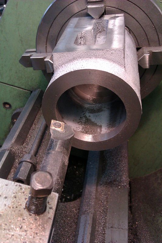
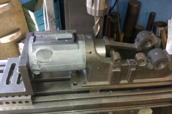
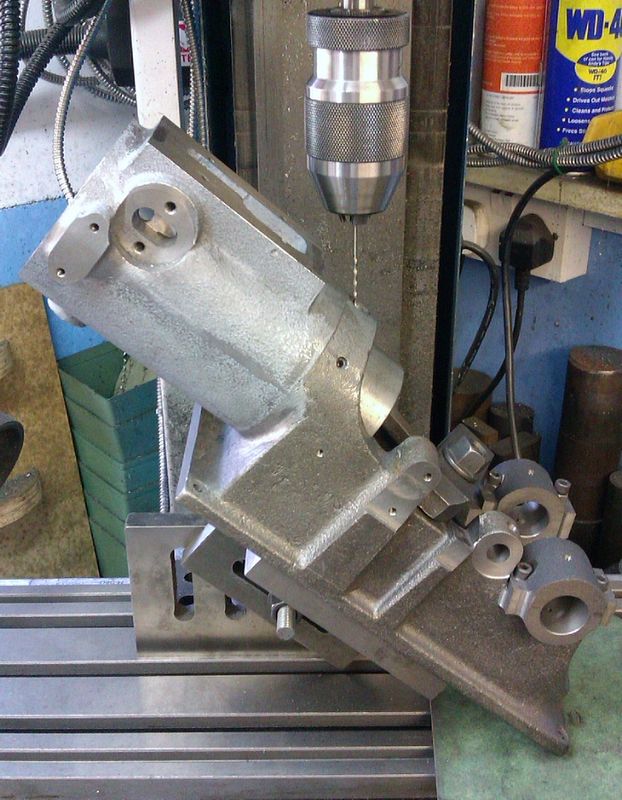
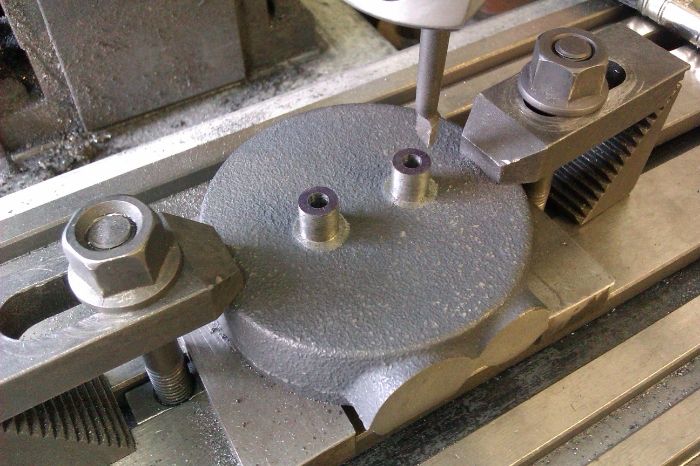
It was then a simple job to clamp the casting the right way up to machine the top surface

IMAG1568_zps7fef3deb.jpg


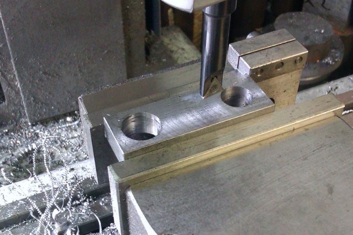
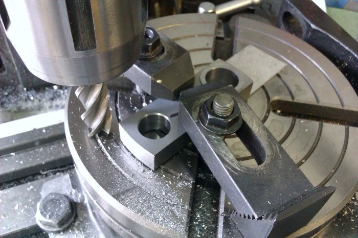
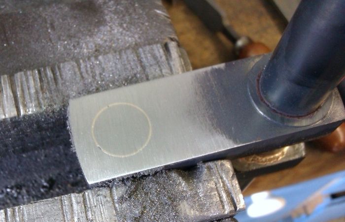
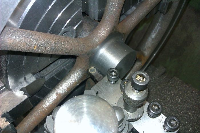
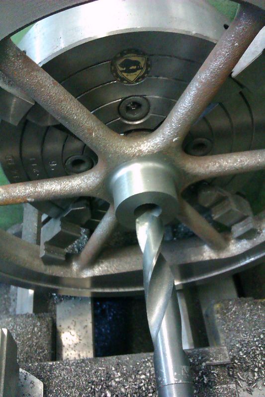
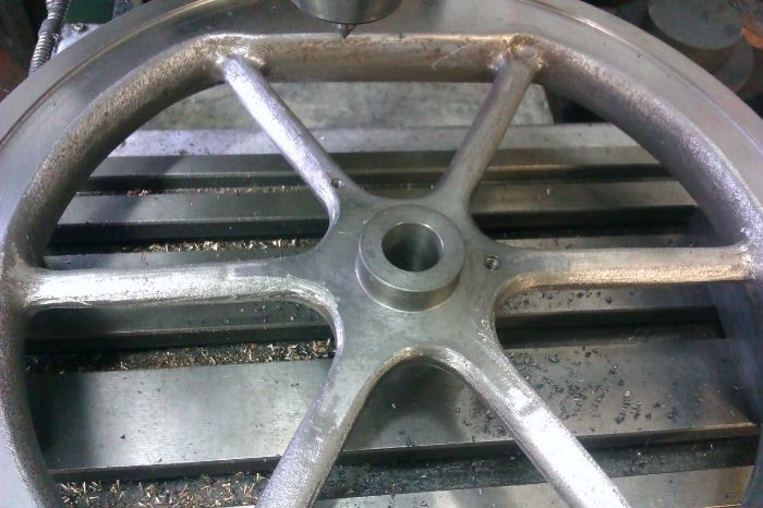
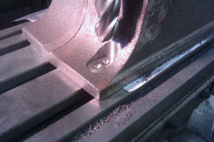
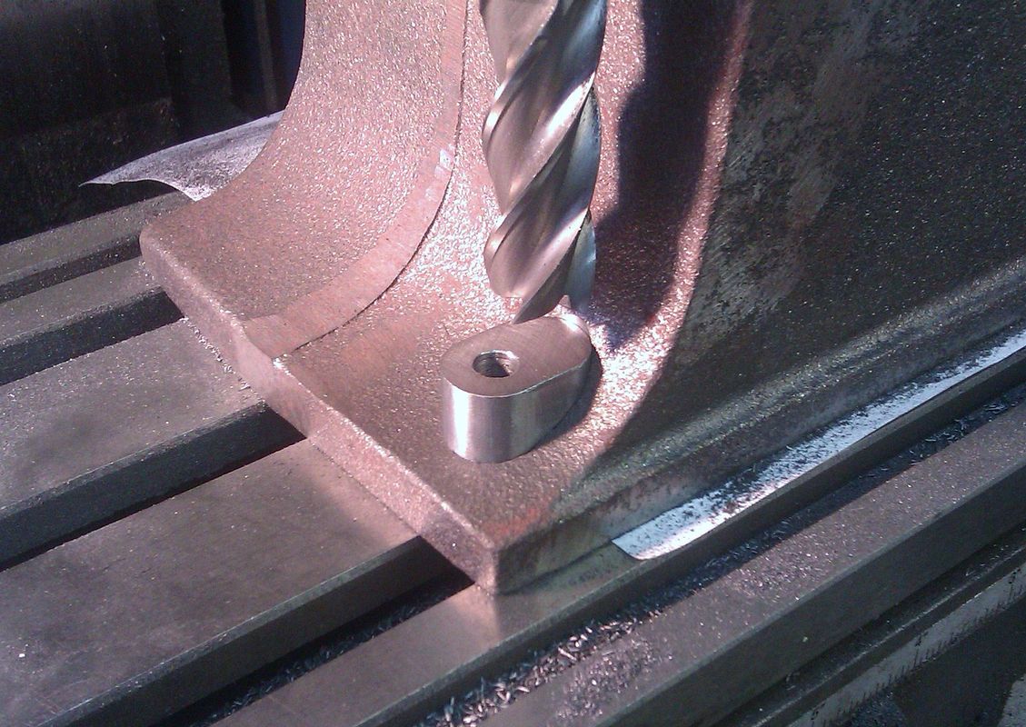
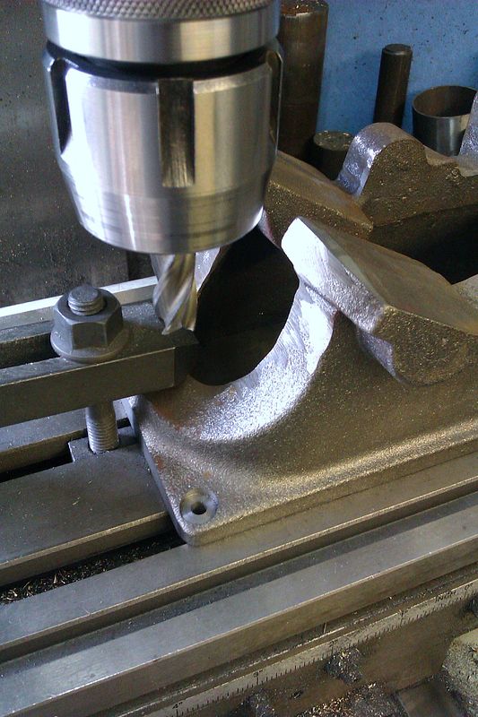
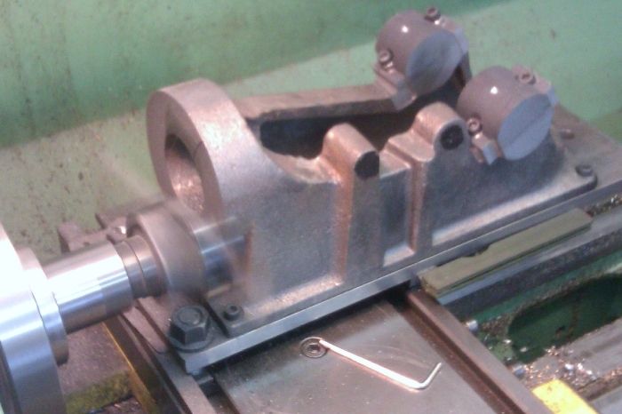
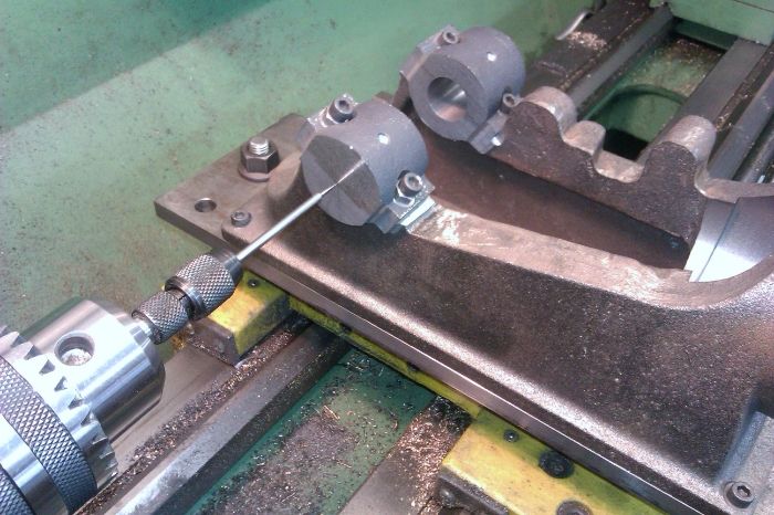
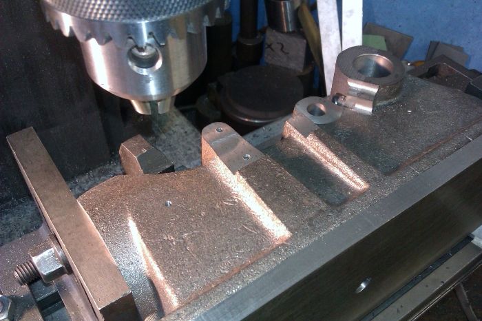
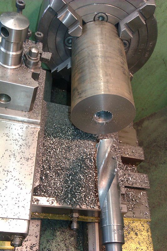
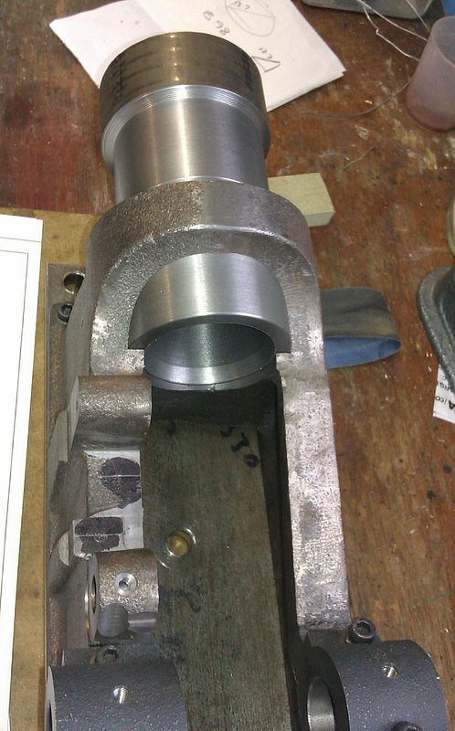
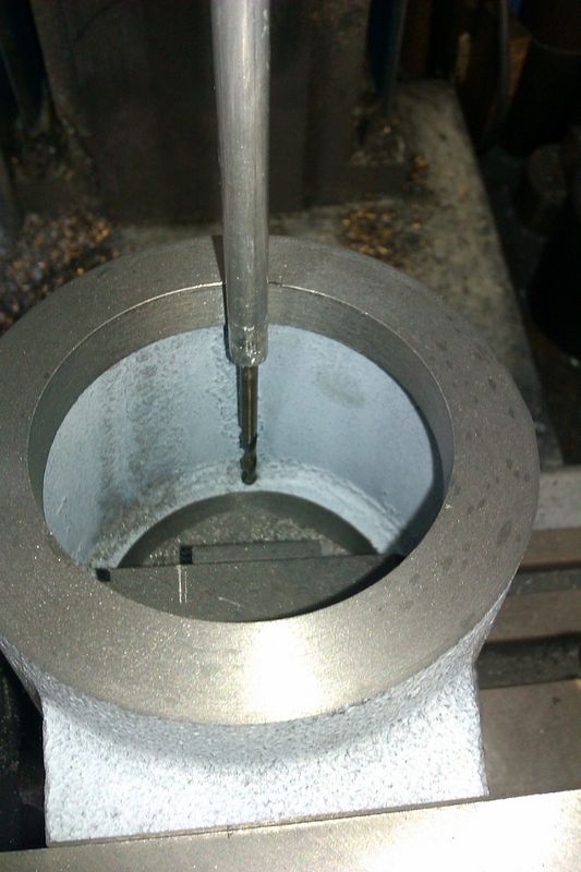
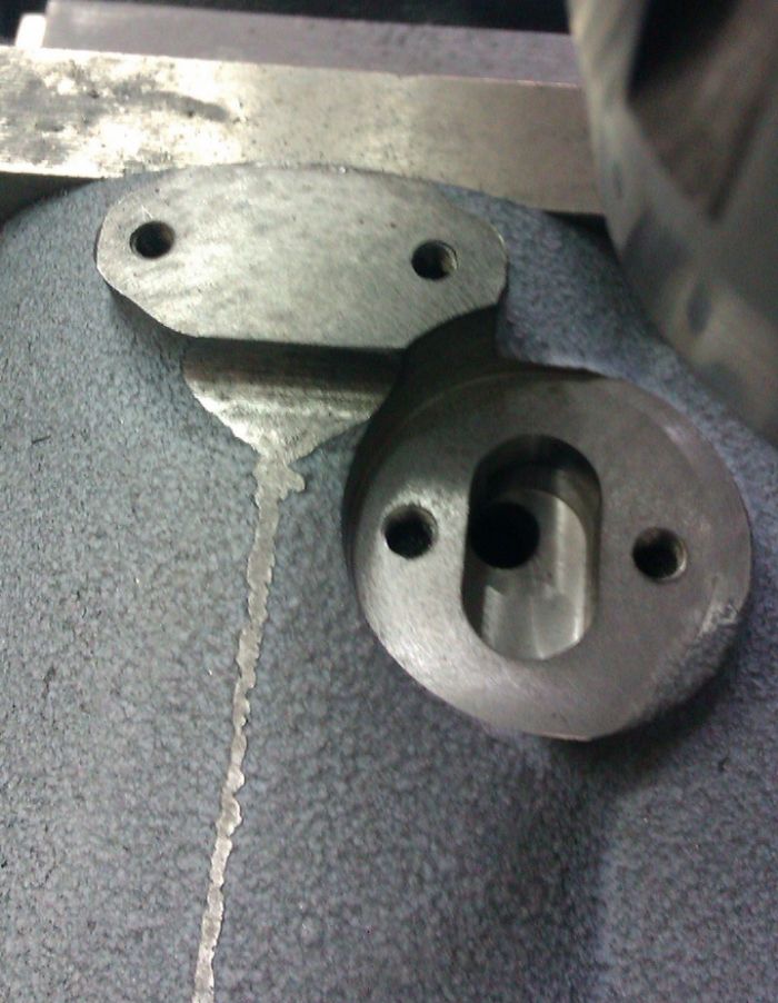
The sockets for the mounting lugs were roughed out with a drill and then finished with a 5/8" milling cutter

IMAG1569_zpsacc6068e.jpg


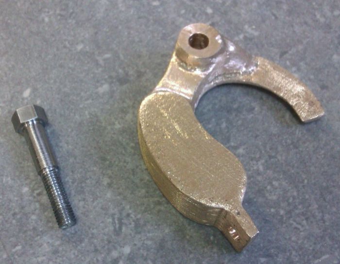
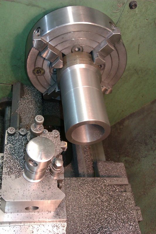
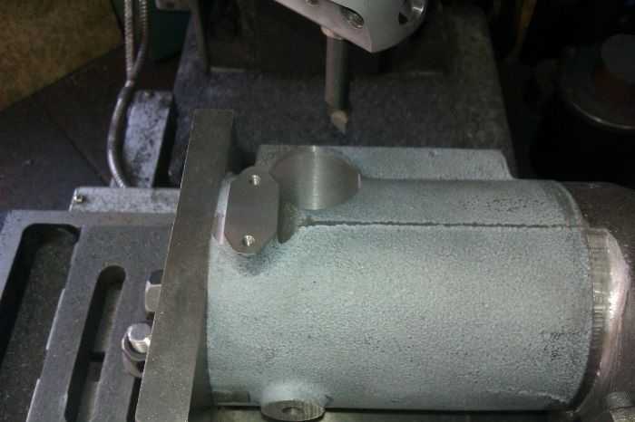
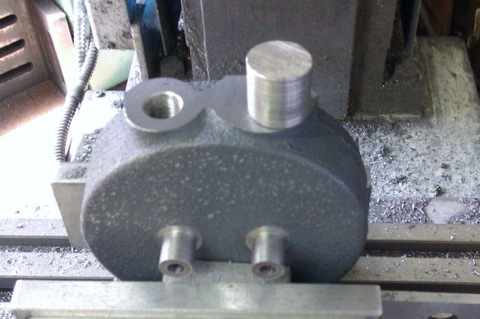
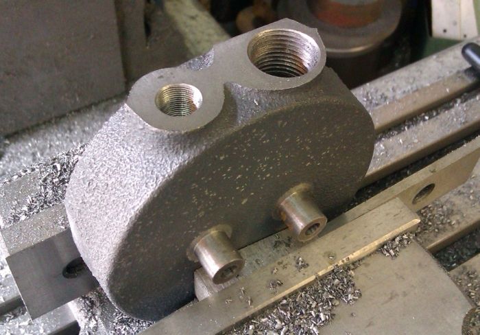
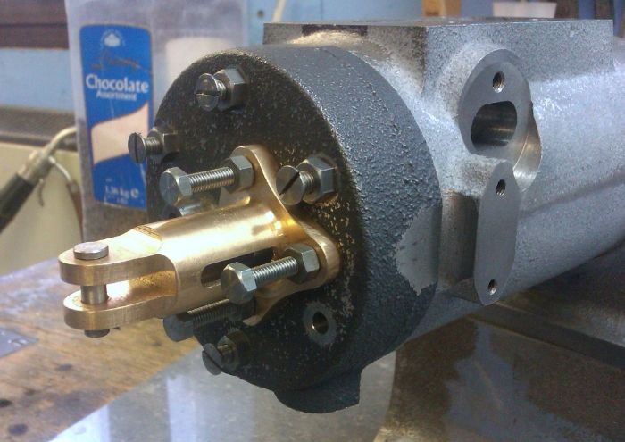
Not a bad fit, these will now be bonded with JB Weld which will also be used to fillet the internal corners.

IMAG1570_zps0c6b1026.jpg


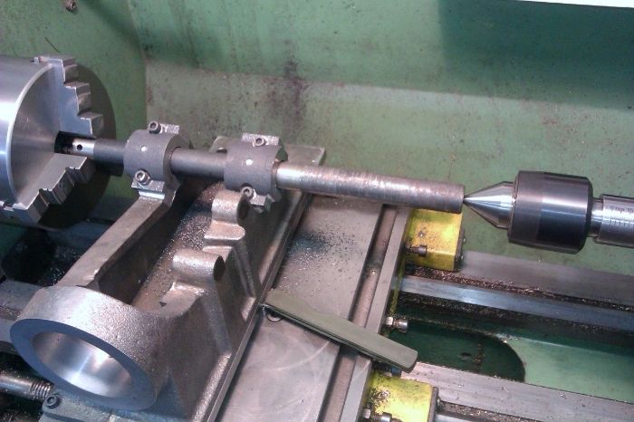
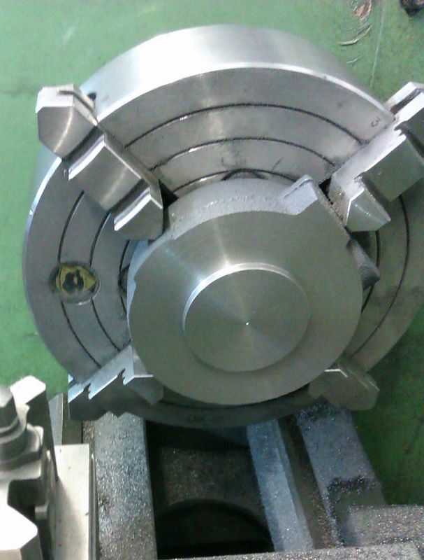
I also took a pass off the ends to remove some of the excess draught angle

IMAG1577_zpse2f2a628.jpg


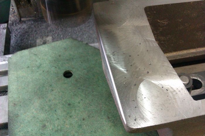
All that work and this piece may not get used, it all depends on how I mount the engine when finished.

J
 
Great work and great photos. Settling in for the ride
 
As I wanted to be able to bolt the bearing caps in place while doing some of the machining on the base these were tackled next.

The two edges were machined first, note the strips of aluminium to take up any uneveness between the vice jaws and the cast surface.

IMAG1639_zps9e14ee00.jpg


I could then support the casting on parallels while gripping by the previously machined edges to bring the base to thickness

IMAG1640_zps1b45a902.jpg


While in this position the step that locates the caps into the base was milled 1/16" deep either side.

IMAG1641_zps7f4dca25.jpg


The two ends were then machined square to the other faces

IMAG1642_zps26f5ab13.jpg


The casting was then sawn in two and the cut ends machined but leaving the caps 1/8" over length.

IMAG1643_zpsddfde64a.jpg


The mounting holes were then spot faced and drilled, make sure you follow the drawings of the base and not the caps for this as the holes are not central on one drawing but central on the other!!

IMAG1644_zpsf0e4e5c8.jpg


J
 
On the full size the cylinder/crankcase is a single casting with the water cavities cast in place, the model uses three parts - the base and cylinder jacket which are both supplied as casting and the liner which comes as a length of dura-bar. There is a lot of work in these three bits so I will break the post up into the various parts.

The base is a bit awkward to hold firmly so after some initial marking out to see what needed to come off where I mounted it the right way up on the mill with packers and feeler gauges to get it sitting true and stop any distortion when bolted down. I took a very light skim off the oiler hole and edges of the bearing housings which gve me 3 nice "legs" to mount it by.

IMAG1628_zpsbdf76008.jpg


I noted the difference in height when machining the 3 points so it was a simple matter to arrange suitable packing so the underside could be milled flat and true. At the same setting the 4 mounting holes were drilled and the ones under the cylinder reverse spot faced with a home made cutter

IMAG1629_zps6e08ba63.jpg


The ones at the crankshaft end were easily done in the conventional way.

IMAG1630_zps0f69cc48.jpg


And a quick test fit on the sub-base. You may also be able to see a vertical line that is cast into the side of the bearing support to indicate where the crankshaft should come and just to the side of that another cast dot also to indicate where the centre should be!!

IMAG1631_zps58cee8dd.jpg


The base was then bolted to a machining plate and mounted at 30
deg to allow the bearing housings to be machined to height, I took this as the vertical cast line and my scribed line at the correct height from the bottom of the casting. you can now see the groove where the bearing caps locate.

IMAG1645_zpsfd9a2cac.jpg


The last bit of metal under the timing gear stud hole had to be removed with a fly cutter and then the mounting holes drilled & tapped.

IMAG1646_zps6162dd21.jpg


The bearing caps were then bolted in place with temporary cap screws and along with the housings machined back to finished width.

IMAG1647_zps50209d9f.jpg


And the final photo in this sequence shows how I had to mount the casting. As I don't have a tilting table or mill head my usual pair of angle plates were set at the required angle and some additional clamping added at the lower end, i looks a bit bodged but was surprizingly ridgid. The machining plate makes it easy to clock the casting true.

IMAG1648_zps536fb724.jpg


J
 
Great work & pictures. Keep us updated please.
 
The next job on the base was to machine the flange for the water jacket to butt up against. The casting was not disturbed from the machining plate and transfered to the lathe. I know the exact centre height above the cross slide is 3.389" so it was a simple matter to subtract the casting and plate thickness from that to arrive at what packing was needed. The side of the machining plate was clocked true to the lathe axis ensuring the face to be machined is at right angles to the beraing faces.

IMAG1668_zps315fe06e.jpg


The flange was then fly cut to the correct distance from the bearing centreline

IMAG1667_zps15b8e1eb.jpg


[youtube]http://www.youtube.com/watch?v=NAgF8tAo-YQ[/youtube]

I then swapped the flycutter for a boring head and machined the socket for the liner. The tool in the boring head is one I use to put a final chamfer on the corners.

IMAG1669_zps0c8ae4c8.jpg


IMAG1670_zps1cbc838b.jpg


[youtube]http://www.youtube.com/watch?v=T87tM6RPm5Q[/youtube]

I then put a rough hole through the cam side bearing before returning to the lathe once again to mount the casting on the cross slide but this time the machining plate was clocked at right angles to the lathe axis and a wobbler used to pick up the location for the hole.

IMAG1671_zps14eda184.jpg


The other bearing housing was then drilled out so a between centres boring bar could be used to open out both housings to finished size.

IMAG1672_zpsa598252f.jpg


With the lathe work done it was over to the mill to machine the timing gear stud hole and faces for the push rod brackets

IMAG1673_zps933f8491.jpg


J
 
Boy this brings back memories. Great work so far. I like all your setups.
gbritnell
 
The next part to be attacked is the cylinder, I spent a while working out where best to place the cuts and put some basic marks onto the casting. The bosses for the rod guide and ignitor can't really be moved so the end faces were marked from the bosses.

IMAG1694_zps9113005a.jpg


The face where the hopper mounts was the best face to use for the initial holding but was not totally parrallel to the cylindrical part so a feeler gauge was used between the casting and the angle plate and a cleaning up cut taken over the head end.

IMAG1695_zpsf2745646.jpg


This freshly machined end was then placed against the angleplate and the top face cleaned up but left oversize at this stage.

IMAG1696_zps7d82a50a.jpg


I then knocked in a temporary plug and marked the centre to make it a bit easier to set things up in the lathe, the machined end of the cylinder was set back against the chuck to keep things square and the end faced.

IMAG1697_zps9eb41aed.jpg


I then mounted the old 4-way toolpost that came with the lathe and centred up a 16mm indexable boring bar and used that to open out the bore. Its not easy to see but the bore does not go all the way through as the end of the liner needs to butt up against the face you can just see in the bottom of the hole. The inner diameter is also 0.010" smaller than the outer so the liner can slip most of the way in before the press fit takes hold.

IMAG1698_zps37cb2c47.jpg


The casting was then rechucked so the other end could have the cored hole clean out to 0.100" undersize and machined to final overall length

J
 
The liner is supplied as a large lump of cast bar about 70mm dia. This was held in the 4-jaw, faced and then opened up first by drilling in stages upto 3/4" and then boring to 0.0100" below finished size.

IMAG1700_zpsc67bbe74.jpg


Approx half the length was then turned down so it was a nice firm fit into the base casting.

IMAG1701_zps2a688d41.jpg


Here it is slipped into place, you can also see that I added a taper to help fitting the piston rings before I removed it from the lathe.

IMAG1702_zpsa9d8328d.jpg


Before I forgot to drill it the coolant drain hole was added to the cylinder with an extended drill, this needed to be drilled before the liner is pressed into place.

IMAG1705_zpsecd778d1.jpg


The liner was then held by the machined end and clocked true before boring the waste out of that end and finally turning the different diameters to press into the cylinder. Not easy to see but there are 3 different dia all only a few thou different from the next.

IMAG1706_zps47a024ff.jpg


The cylinder was then pressed onto the liner while still in the chuck using the tailstock to apply pressure and some Loctite for good measure.
After allowing things to dry over night I inserted packing and shims so the assembly could be bolted down to the cross slide. By doing this with things still in the chuck it kept all the bores true.

IMAG1711_zpsecb900e4.jpg


I then used a 35mm bar between ctrs to bore out the assemble to the required 1.750"

IMAG1712_zpsa26b7756.jpg


And without disturbing anything ran the sprung hone up and down the bore a few times.

IMAG1714_zpsfde1f1ec.jpg


And a quick look down the bore. I was pleased that the butt joint between liner and cylinder did not show so things must have pressed into place as planned.

IMAG1717_zps9ee17ab8.jpg


J
 
Very nice build & also the pictures.
But a question , how do-or did you find a good spot on the castings to put it straight in the mill & the lathe.
My castings are now a disaster & ready for scrap i think so. I'am building the 10H from Stuart.
My other project I put already away. Need a lot to learn.

Barry
 
If you look at all the first photos of each part being machined you will see that they have been shimmed up with packers and feeler gauges or held in the vice with soft packing. This is used to get the irregular cast surfaces into the correct position in no case have I clamped a cast face straight to the mill or in the vice.

With any castings you need to take your time and sit down with them on a surface plate or good flat surface, compare whats on the drawing with what is in front of you and work out how the part needs to be held for the inital cut to make sure the surfaces that will remain "as cast" will be true to the machined ones and to make sure you don't take too much off one surface and then end up not being able to clean up the opposite surface.

It does help to have a good machining allowance on the castings, the iron ones on this engine seem to have 0.100" on most faces though the Bronze ones are a lot tighter and thats likely the same with your Stuart ones.
 
Thanks for the answers. I will study your pic's very good.
 
The next job is to join the cylinder/liner assembly to the base. There was a bit of a difference in the diameters of the two castings so I milled the worse away while it was easy to get at.

IMAG1719_zps0a1b34b5.jpg


There are a couple of options for the joint, I opted for the three pointed grub screws, the positions were spotted through from the tapped holes in the the base and then drilled 0.030" nearer the flange with a 90deg spotting drill. By shifting the hole in this way the grub screw will pull the joint up tight as it screws into the conical hole.

IMAG1720_zps9dedf6b6.jpg


A few drops of 648 loctite around the liner and screw threads and it was screwed together for good.

IMAG1721_zpsafdbc115.jpg


The mounting face for the hopper was then machined to the correct height and the hole for the cylinder oiler drilled and tapped.

IMAG1722_zps595b1c0e.jpg


I then turned the assembly on its side and machined the push rod bosses back to height and cleaned up their sides at the same time. The boring head was used to cut a flat surface for the ignitor to bolt to.

IMAG1723_zps1ea9c6a0.jpg


And a quick test to see how the rod fitted (I'll describe machining the bronze brackets later)

IMAG1724_zpscf478d5a.jpg


A pocket was milled for the ignitor points and a hole drilled through into the combustion chamber.

IMAG1741_zps9ab97387.jpg


The final job was to drill the 1/16" oil hole down to the cylinder at an angle.

IMAG1743_zpsf8879081.jpg


There is quite abit of fettling and some filling required to get this how I want but that will wait until the engine has been test run.

J
 
The next logical part to tackle was the cylinder head. This is quite a simple iron casting consisting of basically a disc with two spigots on one face for the valve guides and a boss on the edge for the inlet & exhaust.

I spent some time accurately locating the centre so that the valve spigots would be in the right place then clocked the casting in and machined the cylinder mating face and spigot to locate into the bore.

IMAG1749_zps152d7b60.jpg


Back for some more marking out of the valve positions and the first was clocked true

IMAG1752_zpsc7a80461.jpg


Then drilled, reamed, valve cavity opened up by boring and the same boring bar used to cut the seat before repeating for the second hole.

URL]


With the head clamped to the mill table the two spigots were brought down to size with the boring head.

IMAG1755_zps0fdb3171.jpg


I then clamped it in the vice and started work on the inlet & exhaust connections. The inlet worked out fine but if placed as dimensioned the 3/8pipe thread would have come out the side of the casting as shown you the bit of rod.

IMAG1756_zps4017c910.jpg


In the end I opted to move the threaded hole away from the edge but keep the 3/8" passage as drawing so it joined with the valve cavity as intended.

IMAG1757_zps29f3320d.jpg


IMAG1758_zps23199772.jpg


The whole cylinder/base asembly has now got quite large which meant it was difficult to locate centre and plot the six cylinder head bolt positions so I drilled the head and used that to spot the hole positions onto the end of the cylinder. In this picture the mill head is up as far as it will go and I had to make a bush to hold a stub length tapping drill in a morse taper collet as there was not room for any type of chuck.

IMAG1760_zps918ab32c.jpg


And finally here it is in place held by some temporary fixings, still needs a good fettle around the edge and I'll also describe the rocker pivot later.

IMAG1761_zps7be2ea2e.jpg


J
 
There is a lot of skill and patience in those pictures!

You guys with your castings are making me want to build a home foundry in a major way. After seeing this I am going to search out a casting kit to build. If that goes well I'll take the plunge into a foundry.
 
I decided to make the crankshaft next so that it could be used to gauge the bore of the flywheels. Two pieces of 1 x 1/2 bar were machined down to 0.875 x 0.45 x 2.625.

IMAG1764_zps307b3a11.jpg


These were then bored 0.625 for the shaft and 0.563 for the reduced ends of the pin

IMAG1766_zps0fc297e8.jpg


Holding them in the 4-jaw a small raised area was formed on opposite sides 0.0125" high giving a finished web thickness of 0.425"

IMAG1767_zpsae189b47.jpg


I then poped then onto the rotary table to add a radius to the ends

IMAG1768_zpsf1d49658.jpg


I used 5/8" precision ground mild steel for the shaft and pin, thse are all the bits ready for silver soldering.

IMAG1769_zpsf3f39c81.jpg


You can see below that the solder was applied to one side only which had a 1/16" deep chamfer around the hole, this should stop the solder wicking all the way onto the working surfaces and save clean-up time.

IMAG1770_zps6e58ddc5.jpg


A little bit of work with a file and it cleans up quite well.

IMAG1771_zpsa4559ee5.jpg


For added security some 1/8" holes were drilled and rods inserted ready to be peined over into shallow countersinks

IMAG1780_zps9e7f7ecc.jpg


After bashing them over a bit of draw filing restores the surface and makes the rods all but invisible

IMAG1781_zpsa3d7c989.jpg


With that all done the middle can be cut out and filed flush

IMAG1783_zpsca071472.jpg


There are a couple of keyways to be cut but they will be cut once all the parts can be assembled onto the crankshaft to get their exact positions.

J
 
With the crank done the next items are the two 10" flywheels. I just managed to hold them with the 4-jaw chuck bearing onto the inner face of the rim. First operation was to turn the outside face, as the tool overhang was a bit long to start with I used a 16mm boring bar as it was thicker than my largest L/H tool but had to mount it upside down and run the lathe backwards.

IMAG1788_zps95d5bc97.jpg


Next the side was machined from the inside outwards using the same boring bar but running the lathe in the conventional manner. I took off approx half the waste which equated to 0.100" which seems to be the usual allowance that these iron castings have.

IMAG1789_zps26171d2f.jpg


It was then a simple matter to advance the tool to clean up the recessed edge of the rim and counterbalance.

IMAG1790_zpsf203e00b.jpg


The hub was then trued up using a button tool to give a nice fillet to the internal corner. I always prefer to turn the rim before the hub/bore as if anything is likely to move it will be while the rim is being machined.

IMAG1793_zpsa9529e7a.jpg


The hole was opened out with ever increasing drill sizes to 9/16"

IMAG1794_zps6ea9f84a.jpg


And then bored out to the required 5/8" using the crankshaft as a plug gauge for a nice fit.

IMAG1796_zps45559999.jpg


The flywheel was then turned around to machine the other side, I used two DTIs, one at the top to get it concentric and the small one at the bottom to make sure there was no wobble.

IMAG1798_zps1dd9907a.jpg


The face of the rim and recess were then machined. The governor side flywheel also needs the area around the hub skimmed smooth. On this flywheel there were a lot of small holes and inclusions which took a lot of effort and one blunted tip to get through but luckily buy the time I got down to finished sizes there were very few pits left visible.

IMAG1799_zps080fab26.jpg


The remaining cast surfaces were then given a going over with the Dremel to remove flash and the worst of the cast texture and the governor flywheel drilled and taped for the weight pivot and spring post.

IMAG1800_zpse91fed61.jpg


The bronze governor weight was cleaned up and the pivot bolt machined.

IMAG1801_zpse23fc015.jpg


And finally bolted in place

IMAG1802_zps7768c551.jpg


J
 
Back
Top