1/3 scale model swivel vice

Home Model Engine Machinist Forum

Help Support Home Model Engine Machinist Forum:

This site may earn a commission from merchant affiliate links, including eBay, Amazon, and others.

hobby

Project of the Month Winner!!!
Project of the Month Winner
Joined
Dec 5, 2009
Messages
510
Reaction score
47
Hi everyone,

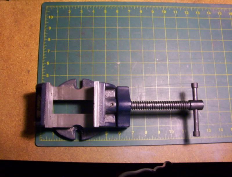
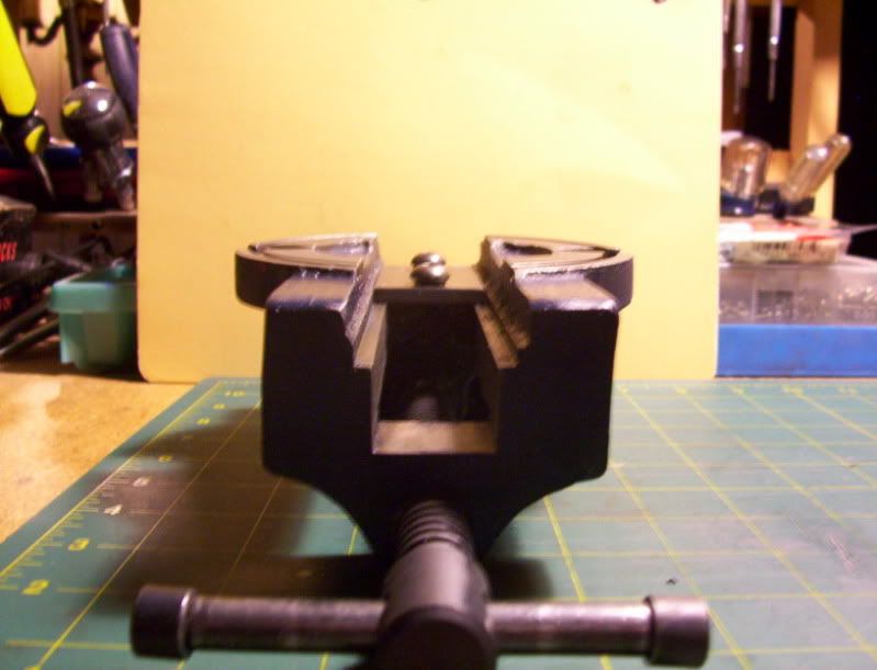
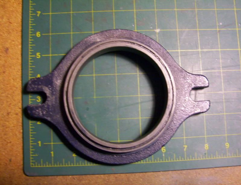
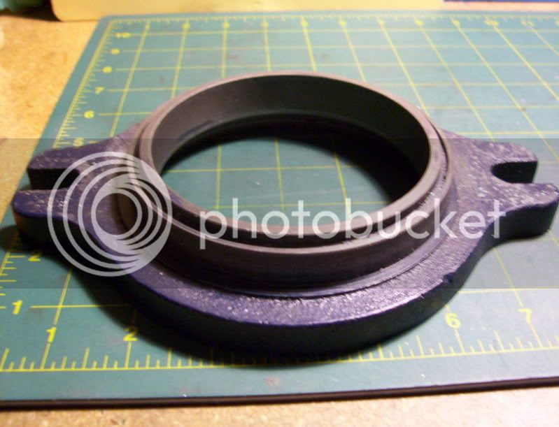
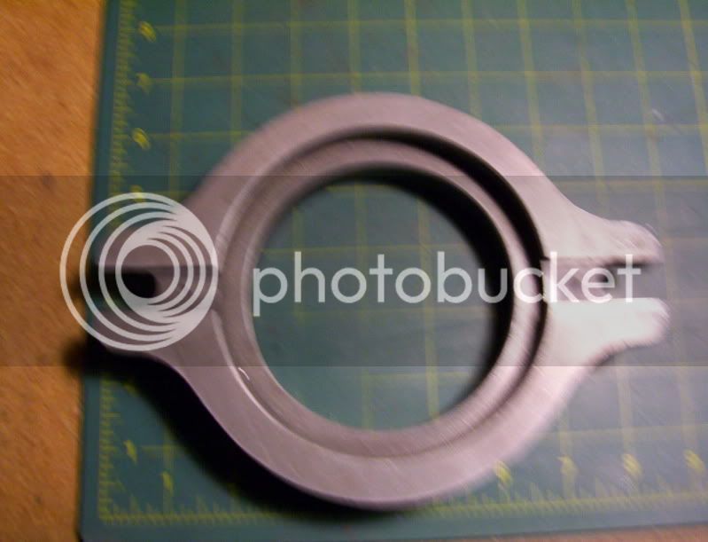
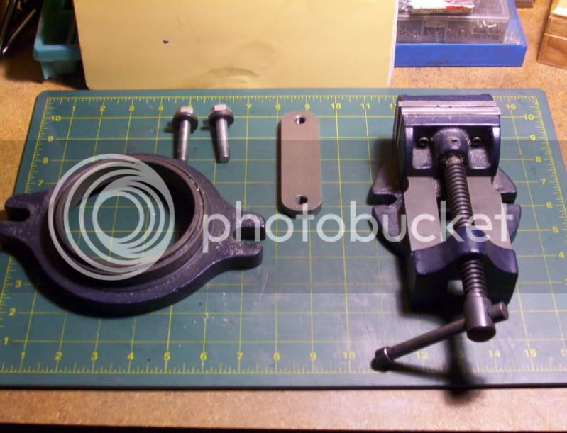
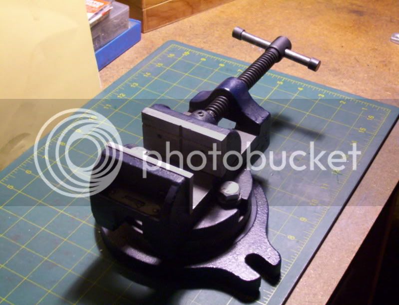
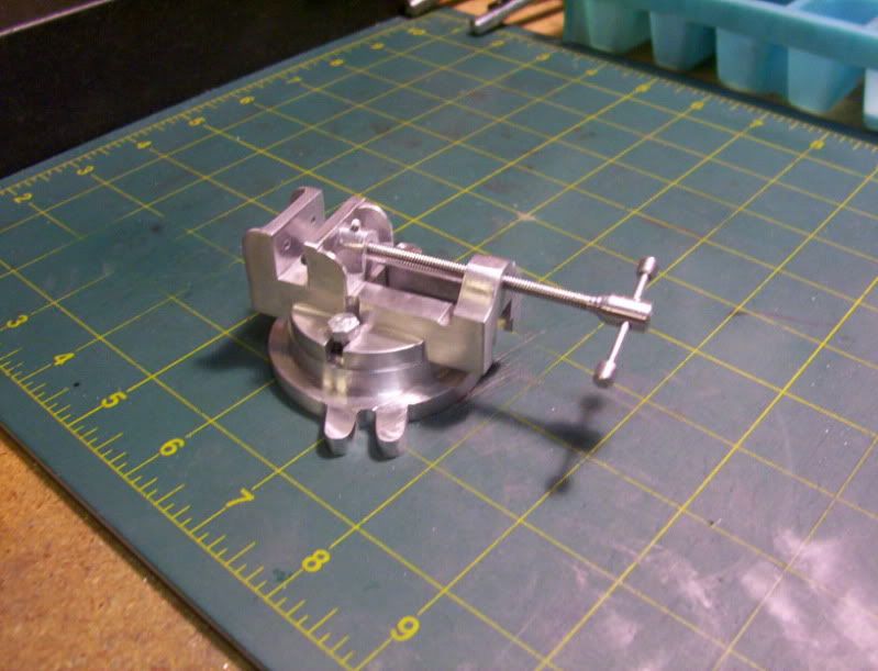
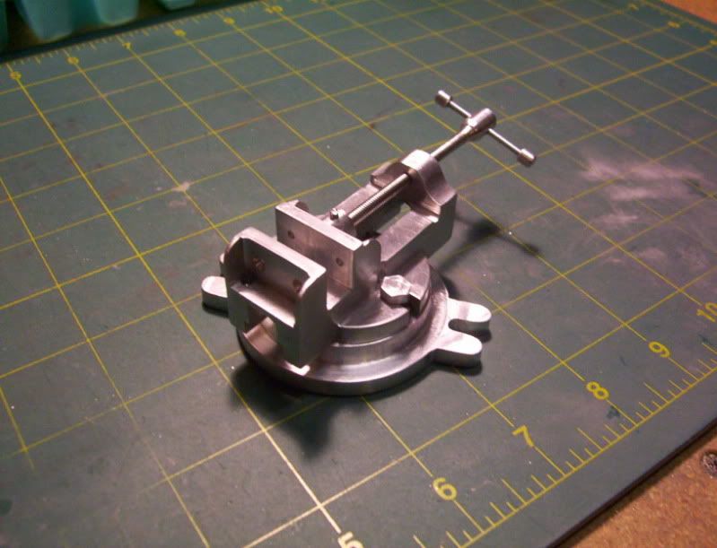
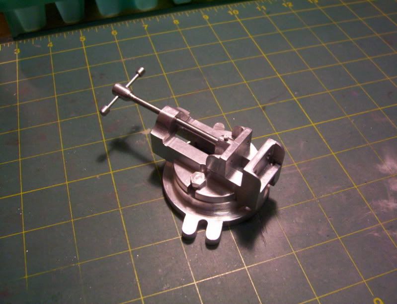
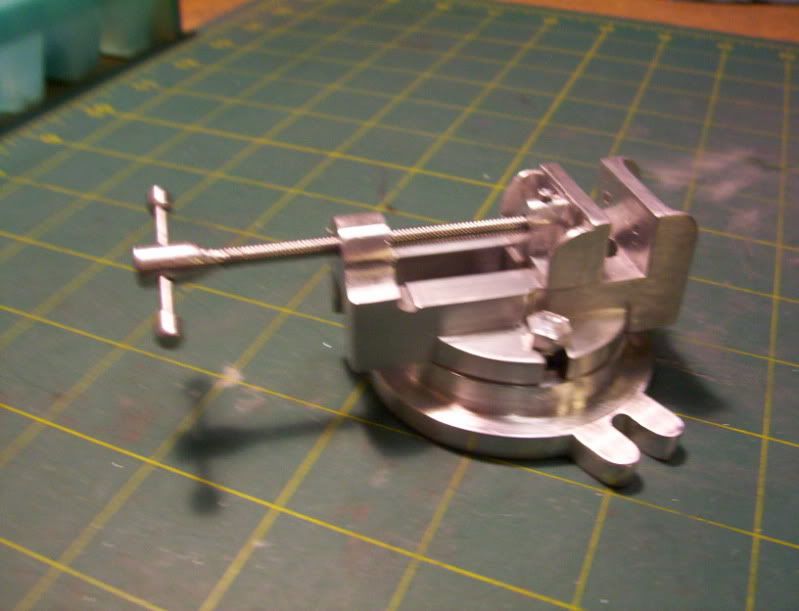
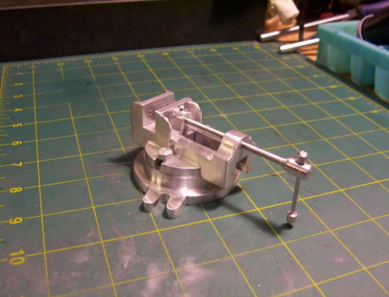
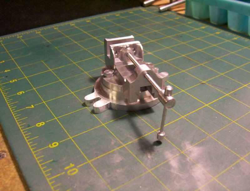
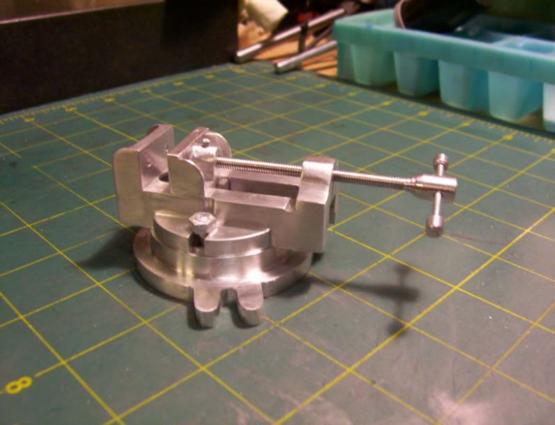
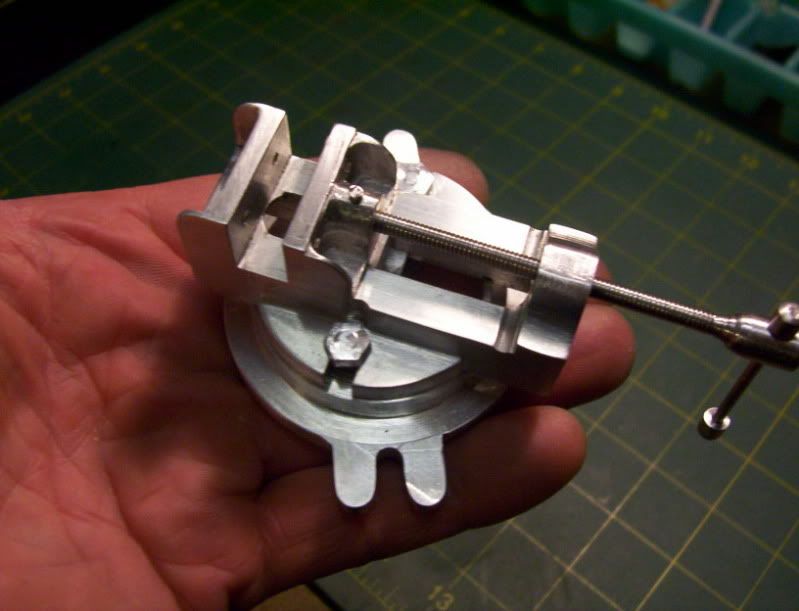
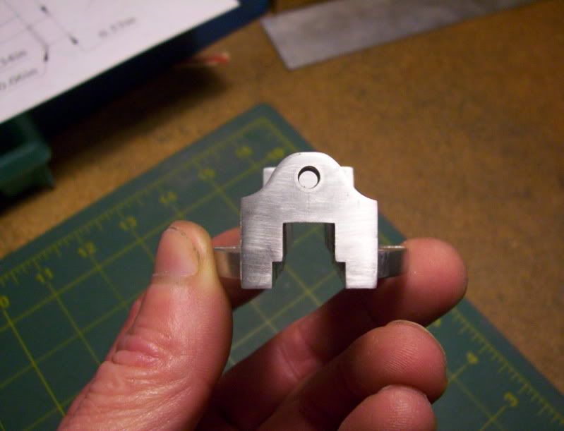
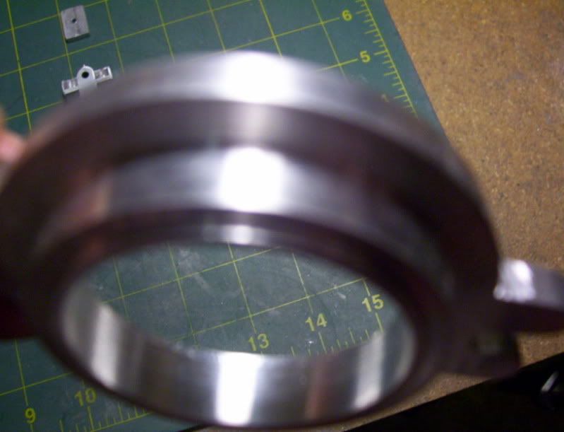
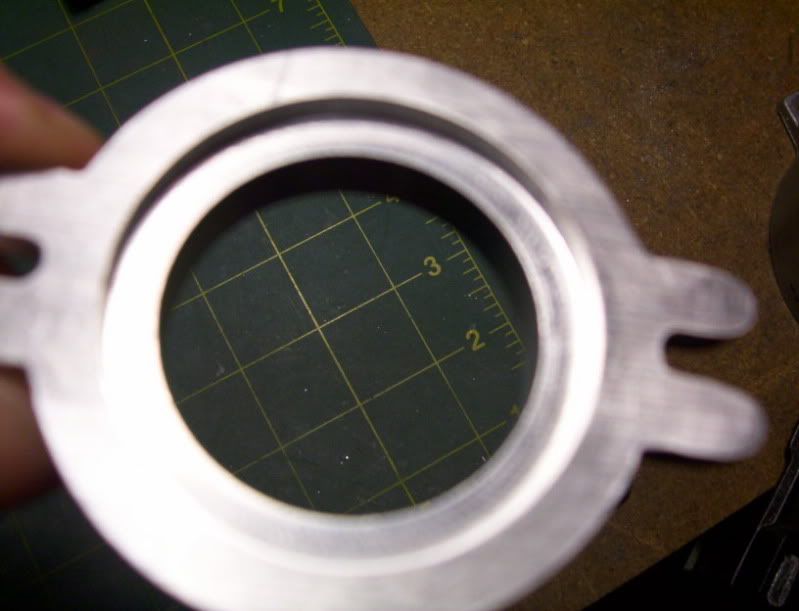
Like to share some pic's of my latest project, I just finished up on it tonight.
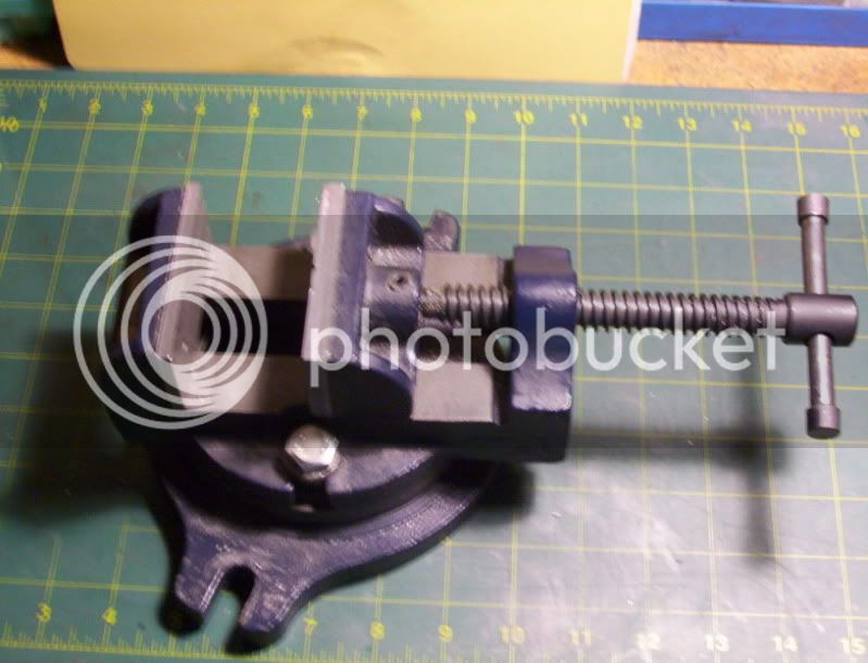
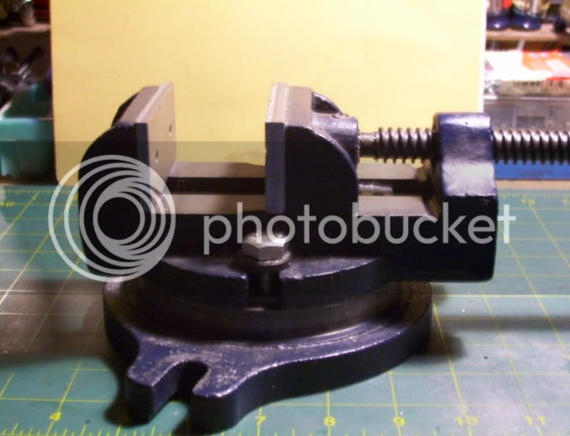
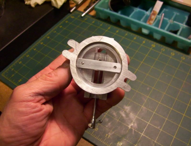
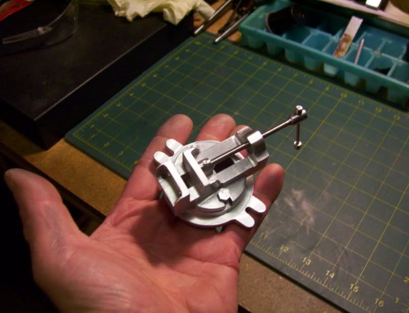
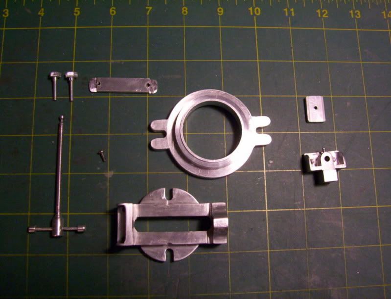
It's a scale model of my swivel vice.
I wanted to make it half scale as my other model vice, however the stock I have on hand is only 1" thick, and I needed 1-1/8" to make it around 1/2 scale, so rearanging the equations, I ended up with a scale model between 1/2 and 1/3 scale.

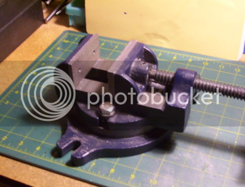
This project took a long time, because I was doing a lot of woodworking outside in my shed workshop, while I had real nice warm weather, but since it is getting real cold out now, I can start playing around in my hobby machine shop inside.
That's why I just now finished this project about 2 months later.


100_2925.jpg


100_2926.jpg


100_2927.jpg


100_2928.jpg


100_2929.jpg


100_2930.jpg


100_2931.jpg


100_2932.jpg


100_2934.jpg


100_2933.jpg


Have a great day...
 
Nice! Thm: Very tidy bit of work indeed!
 
Tel, Thankyou for the compliment.
-----------------------------------------------

@ jacobMcFly

Hi, Ive included some pictures of the parts, as well as a video of the assembly for this project.

I didn't draw up any blueprints for this build this time, I worked directly from the actual vise, and scaled everything from it to make the parts.


Here are all the parts that were made from aluminum.

sv1.jpg


This is the back of the vise where the lead screw threads into, the lowest notch is a rail machined into the top section to allow the top jaw to be fastened to a bracket to allow the bracket to slide.

sv2.jpg


The front fixed jaw part of the vise.

sv3.jpg


This is the bottom side of the top section, it has a groove machined into

sv5.jpg


to allow this flange on the base .

sv6.jpg

sv7.jpg


to match up to it for assembly

And the bottom of the base machined to allow a keeper bar to bolt the top assembly to the base for the swivel and locking function.

sv8.jpg


Here is the video of the assembly process.

"http://www.youtube.com/v/KGNcjZaDUKg?version=3&hl=en_US&rel=0"

I hope this helps,

Thanks.
 
Thanks! The base looks different than i tought. How strong the vice is? I mean [N] of grip(? I'm not sure is my vocabulary allright, I'm not from US).
I'm going to try make it 3D model in SolidWorks first... If I'll have at last a better computer.
Thanks again! :)
 
vcutajar,
Thankyou for the complement.
--------------------------------------------------

JacobMcFly,

The vise was built only as a model, made entirely from aluminum bar stock.
So it would have a very light grip, it could never be used as a vise to hold material for machining, due to the light material it's made up of.

However if it were modified in the design it could be used for light machining, the modifications that would need to be made would be the lead screw should be made from steel, and a steel threaded bushing to act as a nut would need to be installed in the top part of the vise, where resides at the moment a threaded hole through the aluminum.

That would then strengthen the gripping ability of the vise, where as right now, with everything just being aluminum, any heavy preasure on the lead screw could result in stripping the threads on both the lead screw and the threaded hole, in the vice body.

Here are some pictures of the actual vise.

This is the top part of it.

sv9.jpg

sv10.jpg


this is the bottom side of the top part, showing the ring groove.

sv11.jpg


the end views of the top part

sv12.jpg

sv13.jpg


This is the base piece of the vise

sv14.jpg

sv15.jpg


the bottom side of the base piece.

sv16.jpg


some of the parts seperated

sv17.jpg


Finally the top and bottom parts put together of the completed vise.

sv18.jpg

sv19.jpg

sv20.jpg

sv21.jpg


Hope this helps.


Back
Top