Duesenberg Straight 4, quarter scale

Home Model Engine Machinist Forum

Help Support Home Model Engine Machinist Forum:

This site may earn a commission from merchant affiliate links, including eBay, Amazon, and others.
its the little things that take so much time...
here are the distributor and oil pump, still works in progress
(and there's a water pump part currently clamped to my mill,
which is taking up lots of mental energy to design)
 

Attachments

  • IMG_0125.jpg
    IMG_0125.jpg
    3.7 MB · Views: 7
Last edited:
a small amount of progress on the water pump (have mostly been working on other projects)
some (fun for me!) rotary table work was involved, plus lots of filing afterwards
 

Attachments

  • IMG_0136.jpg
    IMG_0136.jpg
    2 MB · Views: 3
  • IMG_0137.jpg
    IMG_0137.jpg
    2.1 MB · Views: 5
some machining operations on the rotary table for the water pump scroll
first is approximating the scroll height as a staircase
second is using a 45-degree end mill to approximate the tubular roundness of the scroll
 

Attachments

  • IMG_0132.jpg
    IMG_0132.jpg
    2.4 MB · Views: 6
  • IMG_0135.jpg
    IMG_0135.jpg
    2.5 MB · Views: 3
speaking of "small parts", I recently ground the pair of cam shafts

(am very pleased with the results I got switching to a CBN wheel
but not sure how to dress the wheel once that is needed)


Attachments

  • IMG_0377.jpg
    IMG_0377.jpg
    493.4 KB · Views: 0
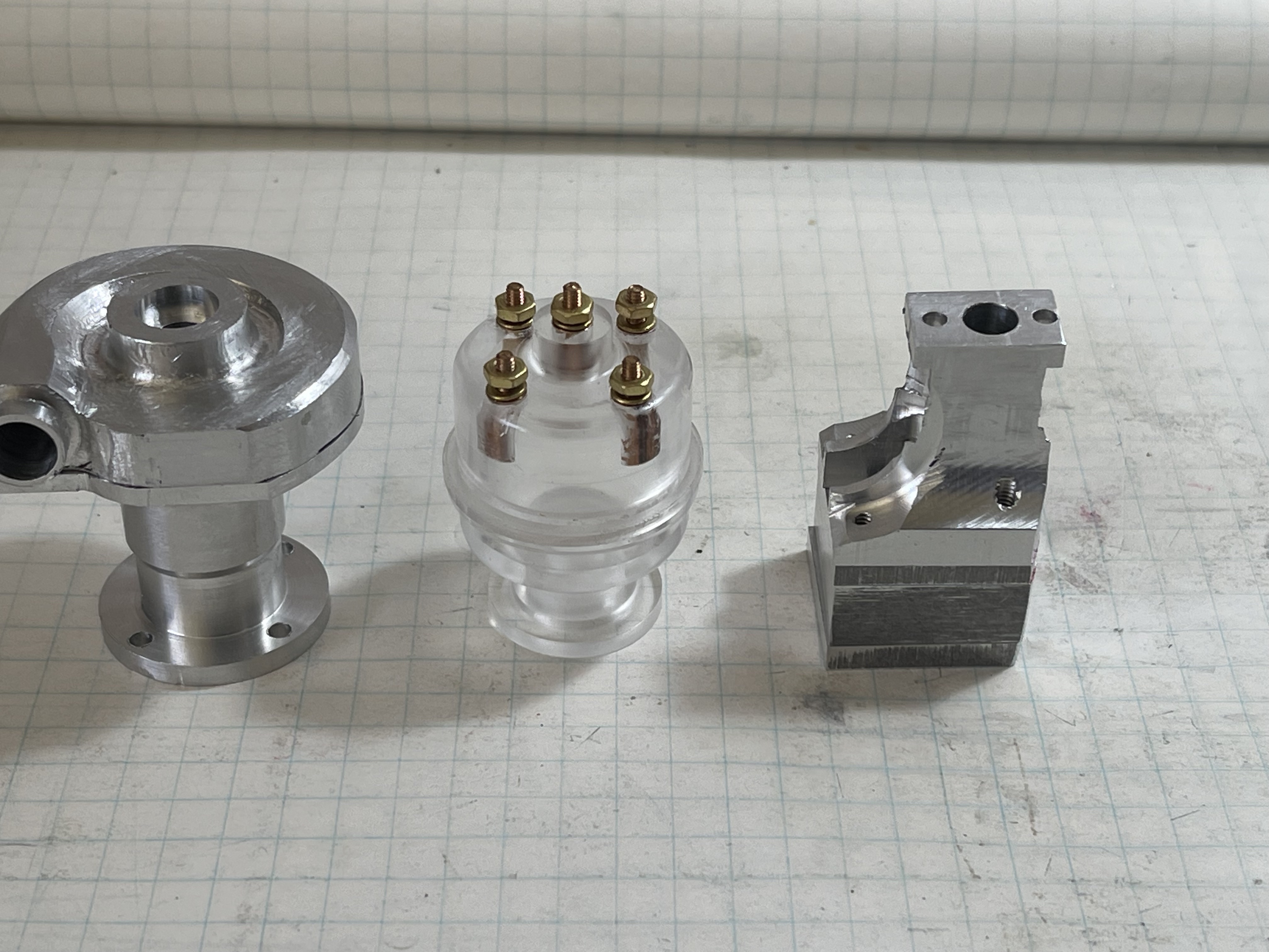
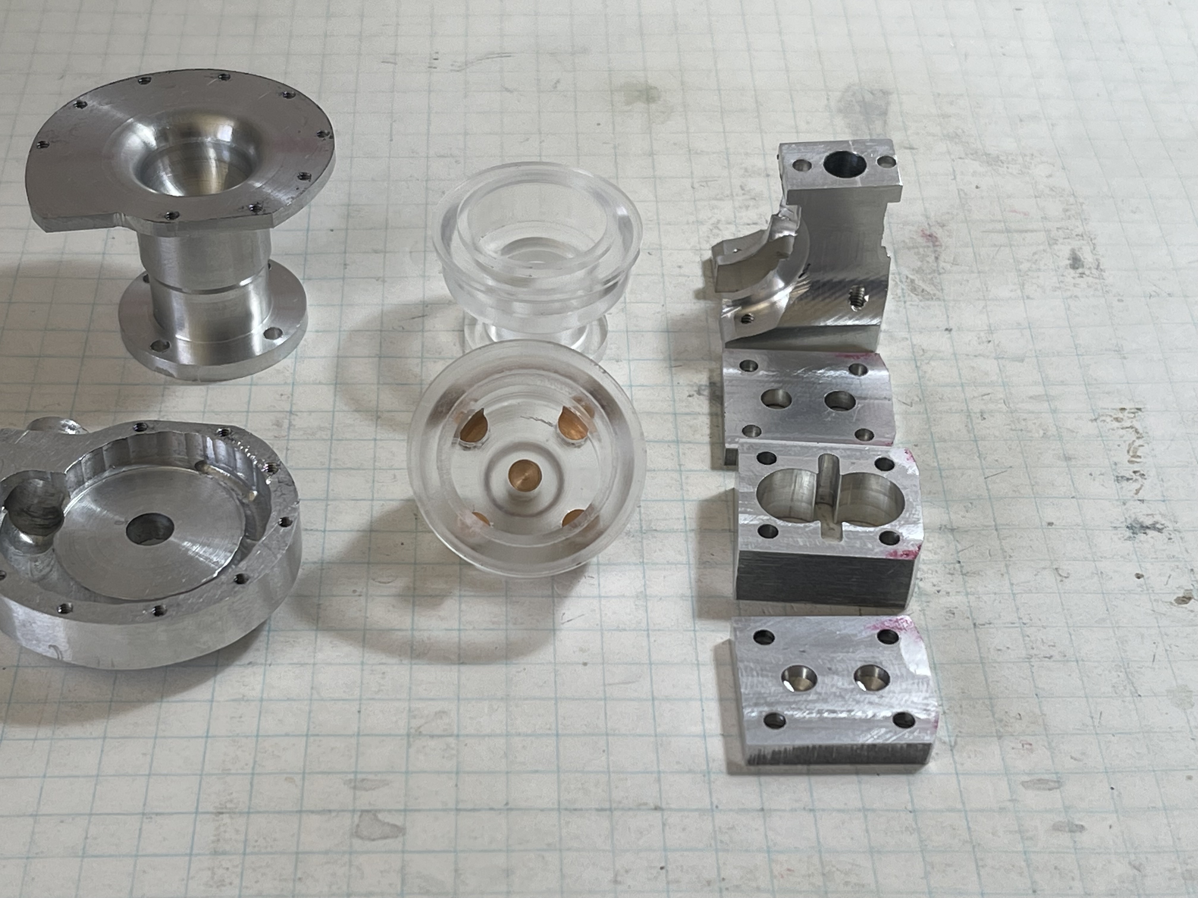
perfection is the enemy of git-er-done, this doesn't look great, but will be functional and well hidden inside the water pump
mostly machined on a tilting rotary indexer, with a little bit of dremel work afterward
the entry and exit blade angles are wrong for a water pump, but won't make much difference for an engine that only gets run for short periods of time for demonstrations (a similar water pump on my Merlin V-12 blew a plastic hose off its fitting, so "good enough for government work" !)
 

Attachments

  • IMG_0395.jpg
    IMG_0395.jpg
    400.9 KB · Views: 0
water pump housing needs inlet pipe
if you have a mill vise you're at the start of a long journey of collecting necessary clamping fixtures and devices :) !!!
 

Attachments

  • IMG_0416.jpg
    IMG_0416.jpg
    582.3 KB · Views: 0
Last edited:
I didn't photo the machining of the flywheel/clutch housing, but here it is, mostly finished. basically it was a lot of rotary table work. now the engine has mounting lugs and I can start on a traditional oak wood box base to mount it on. It has a boss for a starter motor as per full size, but I don't see how to actually get a one-way-roller-bearing in there so that might be cosmetic, and starting might be via a electric drill on the crankshaft.
 

Attachments

  • IMG_0437.jpg
    IMG_0437.jpg
    422.7 KB · Views: 0
  • IMG_0439.jpg
    IMG_0439.jpg
    441 KB · Views: 0
Peter,

Can you put the one way bearing on the crank instead of the the starter?? Better anyway because the belt/chain stops when the engine starts.
normally that would work but with the Duesey there's a ring gear that's cut directly into the flywheel. I guess I could make the ring gear separate, and if I wanted to be clever then use a one-way mechanism to engage it with the flywheel (like pawls and ratchet in a ten-speed hub, those tend to be noisy but with the engine running I doubt you'd be able to hear the ratchets), so maybe that was a good suggestion after all!

the other idea I have in mind is a transmission to bolt onto the flywheel/clutch housing and put the starter motor inside the transmission !
 

Attachments

  • IMG_0441.jpg
    IMG_0441.jpg
    370.8 KB · Views: 0
Last edited:
Separate the gear and flywheel. The gear holds the one way clutch and rotates on the crank. The flywheel is attached firmly to the crank?

that's a good suggestion, but the ring gear should be between the crankshaft and the flywheel, and the flywheel bolts onto a large flange machined on the end of the crankshaft so no way to get the roller bearing in there (without designing a new crankshaft, argh!) that I can see
 
Peter the engine is looking good and the cam shaft grinder works very well.
Is there any information on making the cam shaft grinder

there was a fellow BAEM Club member that was going to turn my camshaft grinder drawings into something readable and/or usable by other people but that hasn't happened yet, and I can't say when I'd be able to get around to it, perhaps I can answer some questions ?
 
Back
Top