Cirrus V8 rotary valve engine build 2x scale up

Home Model Engine Machinist Forum

Help Support Home Model Engine Machinist Forum:

This site may earn a commission from merchant affiliate links, including eBay, Amazon, and others.
Thank you cogsy things are starting to look more clear.A couple of questions for an old thicko.The tool is cut with a straight sided tool form? The tool is passed scross the blank at centre height without moving the blank therefore cutting one tooth and a couple of partial ones.The blank does not revolve as in hobbing?How is the invalute profile achieved? Or does the blank revolve as in hobbing.Please excuse my ignorance
 
No worries Baz. The blank doesn't revolve when the cut is being made and the centre V of the cutter is right on the centre line of the blank. So you have 1 'V' cut straight into the blank, then 2 progressively smaller 'V's each side of that, which are not pointing straight at the centre. You then index the blank 1 tooth and cut again, which recuts some of the 'V's at a slightly different angle and depth. The differing cut angles produce the involute shape. It does mean that you have to index the blank the number of teeth + 3 to ensure the last few teeth are cut completely on both sides.

Hopefully that explain it clearer than I think it does. On the link I gave there is a menu on the right with all the info about how it works and how to do the calculations, etc.
 
Many thanks Cogsy,things are becoming clearer.Please follow my thread
regards barry
ALL THE ABOVE IGNORANCE ON MY PART IS NOW A THING OF THE PAST AS YOU ALL KNOW
I LATER SPENT A LOT OF TIME AND EFFORT TO OVERCOME MY GEARCUTTING INADEQUACY
and i am know confident enough to cut gears
 
Next i made a total of all items.Manifolds,flared pipes compression nuts
I also reworked some commercial springs to 30mm lg from 9/32" dia x 35lg x 0.25wire.Received some 8mm balls from china and assembled everything
Next will be those pesky gears gear 01.jpg

gear 02.jpg

gear 03.jpg

gear 04.jpg

gear cut prep 01.jpg

gear cut prep 02.jpg

gear cut prep 03.jpg

gear cut prep 08.jpg

gear cut prep 09.jpg

gear cut prep 10.jpg
 
I recieved confirmation that the gear DP should be 24.This means that a 2" gear
would have 48 teeth.???. I measured a 50 tooth gear from my lathe and it was just over 2" so somewhere close.I then measured 3 gears from the set and found that the OD was the no of teeth + 1.9mm the depth of the teeth was
2mm. THEREFORE I DEDUCED THAT THE OD WAS THE NO OF TEETH + THE TOOTH DEPTH. iS THAT COINCIDENCE OR IS IT A RECOGNISED FORMULA??
Using this info i i caculated the dia of a 26t and a 52t gear and made 2 blanks from alum.When fitted on the shafts at the fixed centres they overlapped x 2mm,the tooth depth.So therefore we must be in the ballpark.I decided to try to
grind a single point tool to match a 40t gear from the lathe.Hopefully this is the mean of the 26 and 52t gears.Question,should i try to grind a single point tool from HSS or should i turn from drill rod then harden.Depending how successful i am the next step might be to make a cutter as advised by Cogsy and even a new pair of gears from brass.I have ordered Ivan Laws book for some light reading.Watch this space regards Barry
 
The recognized formula for determining the outside diameter of a spur gear with full-depth teeth is to add 2 to the number of teeth and divide the sum by the diametral pitch. For your 24-tooth gear, that would be (24+2)/24=1.083" outside diameter. Applying the same formula to the 48-tooth gear derives an outside diameter of 2.083". The whole depth of the cut, measured from the outside diameter, is 2.250/DP: 2.250/24=0.09375"
I have been following your project with great interest. Very nice!
Craig
 
Thank you Craig,any input is welcome.My problem is that the gears should be
i now know to be DP24 with given od s and fixed centres 14.5 pa
I am trying to determine the mod of existing gears to use as tooth form to grind a tool and also check the dias for a 26 and 52t,which are double the original.How can i accurately measure the mod of the lathe gears to compare to the specified ones of 24dp??.I think that the lathe gears are somewhere near to the specified ones and am hoping to cut the lathe gear form and fit in place of the specified ones
 
I recieved confirmation that the gear DP should be 24.This means that a 2" gear
would have 48 teeth.???. I measured a 50 tooth gear from my lathe and it was just over 2" so somewhere close.I then measured 3 gears from the set and found that the OD was the no of teeth + 1.9mm the depth of the teeth was
2mm. THEREFORE I DEDUCED THAT THE OD WAS THE NO OF TEETH + THE TOOTH DEPTH. iS THAT COINCIDENCE OR IS IT A RECOGNISED FORMULA??
Using this info i i caculated the dia of a 26t and a 52t gear and made 2 blanks from alum.When fitted on the shafts at the fixed centres they overlapped x 2mm,the tooth depth.So therefore we must be in the ballpark.I decided to try to
grind a single point tool to match a 40t gear from the lathe.Hopefully this is the mean of the 26 and 52t gears.Question,should i try to grind a single point tool from HSS or should i turn from drill rod then harden.Depending how successful i am the next step might be to make a cutter as advised by Cogsy and even a new pair of gears from brass.I have ordered Ivan Laws book for some light reading.Watch this space regards Barry

HSS will be fine. Probably better than drill rod hardened!

I'm learning a lot from the exchange between you and cogsey!

Pete
 
Barry, I made 24DP gears for my engine. The pitch diameter of a gear is to about the radial center of the gear tooth and is calculated by multiplying DP times the number of teeth. So a 26 tooth gear of 24DP is 26/24 = 1.083" pitch diameter. The overall diameter of the gear blank is calculated by adding 2 to the number of teeth and divide by the DP. The minor diameter is calculated by subtraction 2 from the number of teeth and dividing by the DP, then subtract another .006" to .010" for clearance.

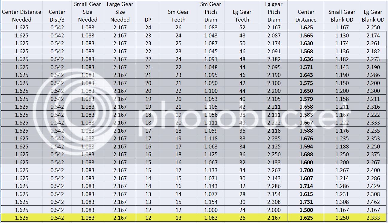
To calculate the size of gears you need, take the distance between the shaft centers, divide by 3 and multiply the result by 2 to get the pitch diameter of the smaller gear. The larger gear is simply double the pitch diameter of the smaller gear.

Based on my gear sizes, my center distance, without consulting the drawings, is probably close to 0.8125" which means yours is around 1.625". If this is correct, you'll need a small gear with a pitch diameter of 1.083" and a large gear with a pitch diameter of 2.167".

I think the easiest solution for you would be to use 12dp gears, double the pitch of mine. That would keep the scale of everything the same and provide you the most accurate spacing. I've run the numbers on everything from 12dp to 23dp and no other pitch will give the correct spacing.

I'll post a spreadsheet showing the various pitches and the distances they provide. By the way, the most common diametral pitches for gears are 12, 16, 20, 24, 32, etc. Finding involute cutters for odd pitches might be difficult.

You might also find a metric gear pitch that suits your needs, but that is another whole area of study that I've never gotten into.

Chuck
 
Last edited:
Attached is an Excel spreadsheet showing gear sizes and spacing for diametral pitches ranging from 12DP to 24DP. As you can see, 12DP is the only one that will get you the exact spacing you need.

Chuck

View attachment Gear Spacing.xlsx
 
Thanks for your info Chuck,i dont have office so i cant see your charts.
I was told the Dp was 24,however the drawing dims seem incorrect
My actual centres are 1.557" and i need a ratio of 2/1 drive.Working on everything else then becomes a problem,especially as i have never cut gears
and have limited knowledge,
Working back thru with Dp and no of teeth to arrive at a centre distance
would be easier and the way to go,unfortuneately i am stuck with what i have
I have 2 sets of metric gears with the lathe and measuring various i have arrived at the dims for a 26 and 52 t gear.I have made 2 blanks and when fitted appear to somewhere near to a few thou.I plan to form a tool to suit the largest gear 127t with 3 cutting teeth as per Gogsy and see how we go
Prior to cutting the teeth in this thread i will open another thread as i have other items to make before starting.Please if you have the time follow my threads to keep an eye on me.I am very interested in how this will turn out
and how close ,if at all the gears will mesh.Another learning curve Barry
 
Here's a JPG of the excel spread sheet. Hope you can read it...

Gear%20Sizes_zpsnjectwtg.jpg
''

By the way, .010" to .020" variation on the gear spacing won't make much difference as long as you don't get them too tight. The looser they are, the more noise they will make, but looser is better than too tight.

Chuck
 
Last edited:
Thanks John ,your dims seem ok but i needed a tooth profile to shape a cutter to
Just opened a thread to proceed with a 26 and a 52 t gear to the mod gears with the lathe .Will have see how it pans out.By the time i have finished i should know a lot more about cutting gears
 
I have just cut the 26 & 52t gears in alum with moderate success.Very pleased but with a few problems to sort out.I have taken 4 videos but they were taking 1.5 hrs each to upload so have just spent a couple of hrs downloading software to compress the files.Now they are taking 5min each to upload to photobucket.First problem was mounted the camera next to the mill on the bench so there is some camera shake.Wont happen again.After cleaning off the burrs the gears do mesh with a few problems
I cut the 52t first in 3 passes.!mm deep then 1.5 then full depth of cut at 2mm deep.During this op the RT locked up so i had to disturb the setup and on a couple of occations i didnt fully clear the cutter before moving a tooth,so slight damage to a couple of teeth. When i had completed 3 passes i carried on on found i was still taking light cuts at the same setting so carried on again all round.I thought i had taken off too much but when finished the OD was within 2 thou
I cut the 26t next and decided to to make one pass at full 2mm depth,when finished the tooth profile did not look quite right and the full dia was was about 30 thou down.When i checked the cutter there was alum build up and that had spoilt the tooth profile somewhat.I cleaned up both gears and they did fit the engine and did mesh quite well.After measuring i found the teeth had not been cut to full depth/profile.I need to add back and side clearance to the teeth on the cutter
use some WD 40 when cutting,make a no of passes rather than one big heavy cut and check were i went wrong with the tooth depth.(bloody chinese dials)Any way very happy so far,will make these adjustments then make another pair in brass,in the next few days.Looking good
 
Last edited:
I made a new blank in brass for the 26t gear.Nudged a few dims and honed the cutter adding a little side and bottom clearance to the teeth with a diamond file
Same setup but cut the gear in 4 cuts starting with 20 thou and finishing with 10 thou.Then went round again at the same setting passing the cutter across the gear 2 or 3 times to polish the teeth and take out any spring same as with a boring bar.Very pleased it looks more like a proper gear.Next will be to the alum 52t gear back thru the setup to get correct tooth depth before deciding if i will make a new one also in brass.The cutter needs sharpening and has a small chip i will probably make another with more clearance
 
I ran the 52 t gear back thru the mill.It meshes well and is acceptable for now
Same problem.The alum welds to the tool and produces a bad cut.Brass cuts much better.However i found the tool easy to make so will make another and play about weith increased rake and clearances.Anything of interest i will post
I made the timing dial from a bit of 4mm alum plate and screwed on the scrap alum 26t gear.(waste not want not) as my old pappy used to say
Final job is to strip down and drill the timing valve.BEFORE I DO CAN ANYONE ADVISE THE PISTON POSITION WHEN THE CYLINDER FIRES.I assume tdc or just past
 
Timing is not critical, but I like to set it so the valve just starts opening at TDC. The holes in the valve tube should be small enough that they are completely closed before bottom dead center.

Chuck
 
May I suggest TapMagic for Aluminum. It will make all aluminum machining operations a breeze with no buildup on the tools and super surface finish. Also works good for any nonferrous metal, including copper, which is notoriously hard to deal with.

This is a very nicely done build! There is a lot of fine craftsmanship in this one.
Thanks for sharing!
 

Latest posts

Back
Top