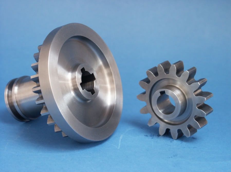
Yes they are from my 2" Traction engine, made to slide along a splined shaft.
The only thing with using a similar method to cut a keyway in a shaft is that you really need a small gap to let the tool run out at the end of the slot, a drilled hole just a fraction bigger than the slot will do. Also watch that the work does not flex away from the tool, use tailstock support if possible
To index those 4 slots and a way to lock the spindle is to put a block between the undersid eof a chuck jaw and the lathe bed and then use a clamp to hold things together.