Reducing Mini-Mill Column Flex (and Column Y-Axis Alignment)

Home Model Engine Machinist Forum

Help Support Home Model Engine Machinist Forum:

This site may earn a commission from merchant affiliate links, including eBay, Amazon, and others.
spuddevans said:
I've read somewhere that some folks have filled the centre of the column with an epoxy-granite mix. This apparently helps to dampen vibration at the same time stiffening the column.

This is a mod I plan to make on my X2 in the coming months along with the same replacing-the-big-washer that you have already done.

I've also seen that others have attached a "I" beam to the back of the column, but that is a bit overkill in my view.


Tim

I beam huh? hmmmmm.......
 
websterz said:
I beam huh? hmmmmm.......

Or you could also use a short length of 4" box section bolted onto the back, but I guess you have to ask yourself when does it become a state of diminishing returns, less and less return on more and more effort and expense.

Tim
 
Fellas, lots of great ideas here.

One of the geniuses of the Sieg X2 world is Hoss from CNCZone. Check out his site, but in particular, this page has a whole collection of column stiffening ideas if you scroll down:

http://www.hossmachine.info/Shop_Info.html

BTW, someone mentioned my epoxy granite fill a ways up. I now have quite a lot of experience with this mill. My sense of it is that the E/G fill improved the rigidity by perhaps 15-20%. My RF-45 now performs almost identically well as a friend's brand new (you don't see those two often) Bridgeport. We were comparing runs with a 3" facemill for example. Unfortunately, it is not as good as his Fadal VMC (LOL!), but it's still pretty nice.

Check out Hoss's site for Sieg X2 stuff, it's very cool!

Cheers,

BW
 
Emanuele, please accept my belated welcome to the forum, pardon my delay in responding, I appreciate your interest in my post.

I don't know why you didn't see some improvement when you added the plate, I would have expected to see some. Could there be some slipping or bending of your clamp setup when you apply the weight of the toolbox? Did you try pushing or pulling directly on the top of the column and noting the deflection before and after the plate? In John Pitkin's writeup, he used a spring scale hooked at the top of the column so he could apply a desired force and measure the resulting deflection. I don't know if you would want to try that or not, but it would be a way to ensure the bending force was applied directly to the top of the column with accuracy and repeatability. I should have done it that way. Instead, I flexed the column with a "firm" push and pull with my hand at the top of the column, with the motor and head still attached. Sorry I can't quantify "firm" in terms of a weight or force, but it was probably much more than your tool box. My push and pull were somewhere between a nudge and a grunt. ;D My flexure measurements were taken from the spindle to the table, similar to the picture below.

SpindletoTable.jpg

I was able to reduce the flex to around 0.0015 inches, about 15 percent of what it was before I started. If I wanted to REALLY push on the column I could probably at least double that.

Another major factor in the rigidity of the un-modified mill may be the amount of compression of the Belleville washer. I don't have any measurements of how much my Belleville was initially compressed. I tend to be conservative when I'm tightening bolts. More compression may be better.

To follow up on black85vette's post above, I think he's right about the ultimate rigidity of the mill being limited by the column mounting. I think most of the remaining flex in my machine is in the bolt and mount that holds the column to the base, so without a major modification to the mounting there will always be some flex. Also, as he says, you will be concerned about flexing with a rearward force on the column. As I look at your plate in your pictures, I don't see anything yet to keep the bottom of the plate from moving toward the base when a rearward force is placed on the column. You will probably want a wedge or other means in the space between the plate and base to keep the plate from moving. Additionally, as I'm sure you are aware, as you tighten those two bolts on the pressure plate you will be tilting the top of the column backwards, thus affecting your Y-axis alignment. I added those two middle bolts in threaded holes in my plate so they would butt up against the base and keep the bottom of the plate from moving inward, and also as a means to align the column in the Y-axis.

Hope this helps. Please keep us informed of your progress and findings.

Regards,
Rudy
 
Last edited:
rudydubya said:
E Also, as he says, you will be concerned about flexing with a rearward force on the column. As I look at your plate in your pictures, I don't see anything yet to keep the bottom of the plate from moving toward the base when a rearward force is placed on the column.

Of course, my plate assembly was incomplete. But I did want to check it as soon as possible.
But I don't think that the absence of the two central bolts would change the results I got.

I'll try to use a spring scale and I want to try different arrangements (the pics and links on the Hoss site are a gold mine): ie, angle plate, U profiles and similar.

Thank you.
 
black85vette said:
In looking at the design of the mill the weak link looked like the way the column was mounted. When you get down to it the entire column is supported on about a 2" base bolted down which is just not wide enough to do the job properly. My opinion is that most of the flex occurs here and not in the vertical column. Along that same thought; the mount has its bolts to the front of the machine. I would expect more flex of the unbolted back side, so putting weight to the front of the column is measuring the weak side of an already weak mount.

I haven't taken a close look at mine beyond noticing it seems kinda flimsy, but it seems there could be some sort of re-design of the column-tilt-to-base piece. And while he's at it, a guy might be able to mount the column a little higher and gain more Z travel.
 
rudydubya said:
Emanuele, please accept my belated welcome to the forum, pardon my delay in responding, I appreciate your interest in my post.

I don't know why you didn't see some improvement when you added the plate, I would have expected to see some. Could there be some slipping or bending of your clamp setup when you apply the weight of the toolbox? Did you try pushing or pulling directly on the top of the column and noting the deflection before and after the plate? In John Pitkin's writeup, he used a spring scale hooked at the top of the column so he could apply a desired force and measure the resulting deflection. I don't know if you would want to try that or not, but it would be a way to ensure the bending force was applied directly to the top of the column with accuracy and repeatability. I should have done it that way. Instead, I flexed the column with a "firm" push and pull with my hand at the top of the column, with the motor and head still attached. Sorry I can't quantify "firm" in terms of a weight or force, but it was probably much more than your tool box. My push and pull were somewhere between a nudge and a grunt. ;D My flexure measurements were taken from the spindle to the table, similar to the picture below.

SpindletoTable.jpg

I was able to reduce the flex to around 0.0015 inches, about 15 percent of what it was before I started. If I wanted to REALLY push on the column I could probably at least double that.

Another major factor in the rigidity of the un-modified mill may be the amount of compression of the Belleville washer. I don't have any measurements of how much my Belleville was initially compressed. I tend to be conservative when I'm tightening bolts. More compression may be better.

To follow up on black85vette's post above, I think he's right about the ultimate rigidity of the mill being limited by the column mounting. I think most of the remaining flex in my machine is in the bolt and mount that holds the column to the base, so without a major modification to the mounting there will always be some flex. Also, as he says, you will be concerned about flexing with a rearward force on the column. As I look at your plate in your pictures, I don't see anything yet to keep the bottom of the plate from moving toward the base when a rearward force is placed on the column. You will probably want a wedge or other means in the space between the plate and base to keep the plate from moving. Additionally, as I'm sure you are aware, as you tighten those two bolts on the pressure plate you will be tilting the top of the column backwards, thus affecting your Y-axis alignment. I added those two middle bolts in threaded holes in my plate so they would butt up against the base and keep the bottom of the plate from moving inward, and also as a means to align the column in the Y-axis.

Hope this helps. Please keep us informed of your progress and findings.

Regards,
Rudy

Hey Rudy, can we get some close-ups of your indicator holder? Is it shop made? I need one of those!
 
Greetings websterz, yes, bought it from LMS, see the link above from prof65. I haven't had any problem with it not holding my indicator firmly, but do have to unscrew the plastic cap on the end of the clamping screw a little to get it to clamp tight on the spindle. Been thinking of replacing the clamping screw with a longer version...

Rudy
 
Hi all
I'm new to this forum and taught I try to post some pictures of my X2 mods.

Here is my take on the stabilisation of the X2 column.

I didn't find a 24mm drill for the hole for big bolt in the back, but milling the hole on the rotary table worked as well, just took a little longer time.

Milling24mmhole700.jpg


Here is the finished modification. My intention is, when tramming the head in x direction, to first tighten the small bolt at the top then tighten the big nut. This is to prevent the column to tilt when the big nut is tighten.

X2columnmod700.jpg


Here is the modification from the side. Also my way of stabilisation the head/column while unscrewing the big nut.
I have only done a very unscientific test so far, putting a Dial Gauge in the spindle and pushing hard with one finger on the top of the column.
This gave that the flex was about half the reading after the mod. I will try this test again without the Belleville washer to see how much flex is from this washer


X2sideview.jpg


I have also converted my mill with the Serling steel belt drive kit.
But you might see that I have made my own, smaller primary pulley, to get some torque back.
Much needed especially when drilling.

Beltdrive_700.jpg


regards
Lars
 
Lars;

Nice looking job. Slot on the plate is a great addition. Thm:
 
wow that is a great idea nice work on it and thanks for posting it Thm:
 
Very nice work Lars, thanks for sharing the ideas and pictures, and welcome to the forum. Would love to see or hear more about your shop and equipment and your interests in the hobby. There is a welcome section in the forum if you would like to introduce yourself to the forum members.

Regards,
Rudy
 
rudydubya said:
After I finished the spindle-column alignment on my Harbor Freight mini-mill (
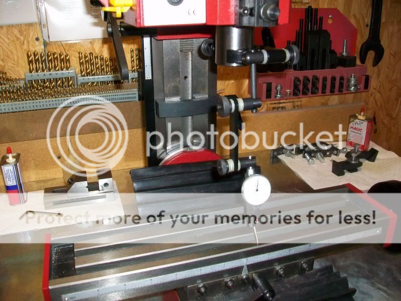
http://www.homemodelenginemachinist.com/index.php?topic=6007.0), I still didn't get a good tram in the Y-axis. It measured about .004 (all my measurements are in inches) out of alignment, as if the column was tilted to the front just a tad. I also had a significant flex in the column. With a firm push or pull on the motor or top of the column in the Y-direction, I could get almost +/- .010 (2.5 tads) of up and down movement of the spindle relative to the table. I wanted to fix, or at least reduce, the flex, and planned on correcting the column-table alignment while I was at it.

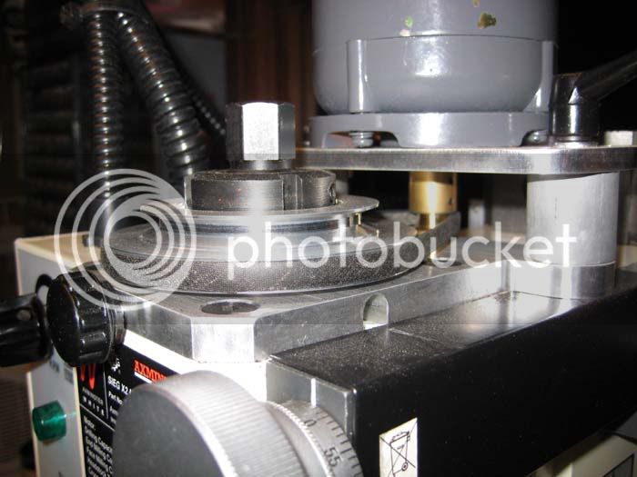
From what I had read about the column flex, the consensus was that the major cause was that big Belleville washer under the big nut at the back of the column (with maybe some compression of the column wall under the washer thrown in), and by replacing the washer with a flat plate you could reduce the flex. Some folks added angle brackets and braces to the plate to make the column even more rigid. I decided on a simple flat steel plate bolted to the back of the column to replace the washer and act as a reinforcement up the column axis.

01-MillNutandBelleville.jpg


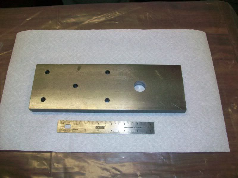
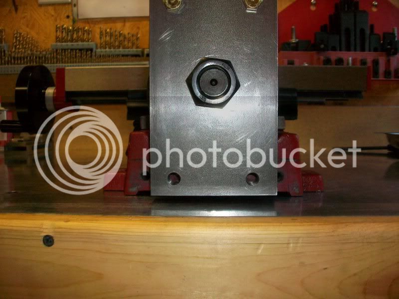
I made a column reinforcing plate (hereafter called a column plate) out of 3/4" thick, 4" wide steel, and drilled holes for some 3/8" bolts plus one 15/16" hole for the big pivot shaft. I used the center of the plate as a reference to locate the bolt holes. Most of you probably know I shouldn't have. The pivot shaft is not on the centerline of the column. It is centered on the ways, but the ways are shifted over about 1/4" on the gib side of the column. I never noticed it before. Must be a lesson in there somewhere. Anyway, my hole locations were far enough in from the sides of the plate to still work on the column, it's just a little off-center.

02-StiffeningPlate.jpg


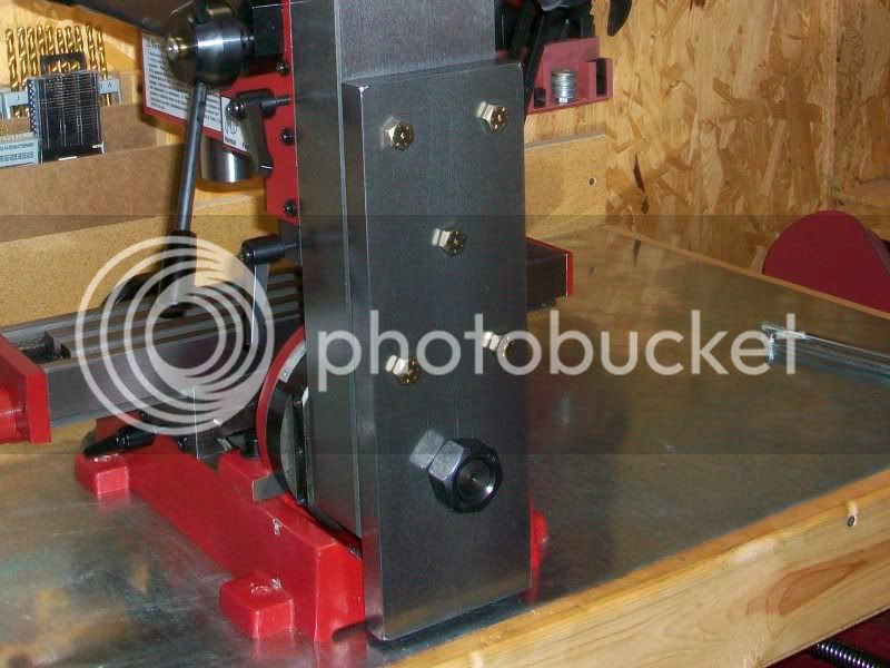
I match-drilled holes for the bolts into the back of the column, tapped them for 3/8" threads, and bolted the plate to the column. The flex was reduced to less than half of what it was, now about +/- .004, but still more than I wanted, and I hadn't fixed the Y-axis tram yet either.

03-ColumnWithPlateOnShaft.jpg


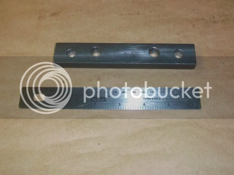
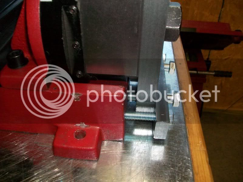
I drilled four holes in a piece of 1/2" thick, 1" wide steel, one at each end for 3/8" bolts, and two near the center for 7/16" bolts. The end holes were far enough apart to clear the edges of the column plate. This would be a pressure plate to push on the bottom of the column plate.

04-PressurePlate.jpg


I drilled and tapped holes into the base of the mill itself to match the 3/8" outside holes in the pressure plate, and drilled and tapped through the column plate only for the 7/16" holes, not into be base.

05-PlateThreadedforPressurePlate.jpg


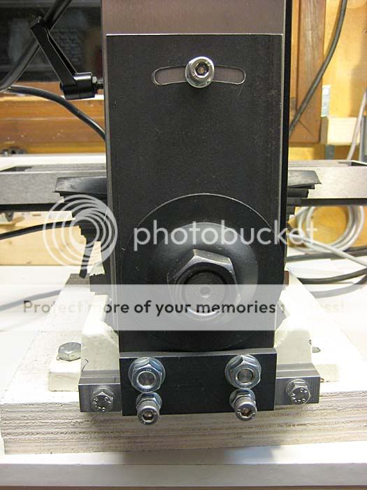
I bolted the pressure plate to the base of the mill with the outside bolts and tightened them until the column was pulled in enough to tilt the column back and eliminate the .004 Y-axis tram error. I then inserted 7/16" bolts through the center holes and screwed them through the column plate until they were snug against the mill base. With the end bolts pulling on the column, and the middle bolts pushing on the column, the bottom of the column was locked in place and the flex was reduced to about +/- .0015.

06-FinalSetupBackView.jpg


07-FinalSetupSideView.jpg


Some final notes:

With the bolts in place, I can no longer rotate the column side-to-side to mill at an angle. I have never used that feature anyway, so it was not a concern to me. Also, my mill was trammed in the X-axis to my satisfaction before I drilled the holes at the bottom of the column plate, but I left plenty of clearance around the 7/16" bolts in the pressure plate to allow some slight angle adjustment for tramming, if necessary.

My mini-mill Y-axis alignment required the bottom of the column to be pulled in toward the base, so the 3/8" outside bolts were tightened first, as evenly as possible to avoid any twist. Then the inside 7/16" bolts were screwed in just tight enough to eliminate any flex. If the required correction was the other way, the center bolts would need to be screwed in first, pushing the bottom of the column away from the base, and then the outside bolts tightened to eliminate any flex.

If I were to do this mod over, I would use a thinner column plate, say 5/8" or 1/2" so the big nut would be sure to grab all of the pivot shaft threads. The 3/4" plate I used just barely allows that. Also, my plate was 12" long. If I were planning to fit my mill with an air spring kit like the one sold by Little Machine Shop, I would shorten to column plate to maybe 10" long so it wouldn't be in the way of the hole in the column required by the kit.

The remaining minor flex in the column assembly is probably due to bending of the pivot shaft and/or the pivot plate. I couldn't think of any practical way to eliminate it entirely.

Drilling into your mill might void any existing warranties. I never had an extended warranty on my mill, so it wasn't a concern.

I think that's about it, thanks for reading.

Rudy

Hi I know this is a old thread, I have a Sieg SX2 and want to stiffen up the column.
I know my tram is out on my Y axis as when feed ali into the cutter away from myself the front edge of the cutter is cutting more than the rear. I've also measured it roughly when i trammed the X axis.
If i swing a dial indicator from one side of the front of the table to the other so that it touches, then move the DTI to the rear of the table it doesn't touch.
So before i start shimming the Y axis i need to sort the flex out in the column.
Can i just use a piece of black steel flat bar for the rear plate?
http://cgi.ebay.co.uk/Black-Flat-St..._Metalworking_Supplies_ET&hash=item43a57f8e0f

Do i need to machine the plate surface or can it just be slapped on as is?

Thanks
 
Goldigger, welcome to the forum. It does sound like your Y-axis is a bit out of tram. Not unusual with the Sieg X2 family of machines, from what I've read.

I'm not familiar with black steel, but the steel plate I used was nothing special, just some cold-rolled I had left over from making flywheels. I think most any good steel plate would work. I've read about some folks that just used angle iron. But if you need confirmation, maybe one of the members familiar with the material could offer an opinion if you posted a question in the questions and answers or metals forum.

If your SX2's column is identical to my X2, then a 100mm by 15mm bar sounds about right. Mine was thicker, but as I mentioned, I should have used a somewhat thinner plate to ensure the nut could get a good grab on the pivot bolt.

I didn't do any machining on the plate. I looked at it, and it didn't appear to be warped or twisted when I laid it down flat on my workbench, so I used it as it was.

Good luck with your mod, and keep us informed on your progress. When you get time, tell us a little about yourself and your interests and machines in the welcome forum. And you know we like pictures.

Regards,
Rudy
 
Hi Rudy,
Thanks for your reply, ill introduce myself in the welcome fourm.
I'll also update this thread when i have modded the column. Im 99% sure my SX2 is the same column and base as the X2, the only differences are:
500w brushless motor
Belt drive
varible speed rather than some of the X2's that had a 2 speed box.
 
You will not regret the effort to do it.... this mod makes HUGE differences in the cuts you can make.
 
I hope so, its quiet annoying when the head starts to shake when using a 16mm end mill and plunge milling..
 

Latest posts

Back
Top