You are using an out of date browser. It may not display this or other websites correctly.
You should upgrade or use an alternative browser.
You should upgrade or use an alternative browser.
Reducing Mini-Mill Column Flex (and Column Y-Axis Alignment)
- Thread starter rudydubya
- Start date

Help Support Home Model Engine Machinist Forum:
This site may earn a commission from merchant affiliate
links, including eBay, Amazon, and others.
The thing was just a beast (the solid column kit that is). I scratched out my 4 80% AR15 lower receivers in no time... Everybody calls me crazy all the time for driving to get the answers to this stuff and this pays off every time. I had all the bugs chased out before starting the project...
I outfitted the mill with the solid column kit (using the methods I posted a couple posts ago), put the air spring on it, the belt drive conversion, and outfitted it with those IGuaging DROs... Thing ran like butter...
Now I am in full on finishing mode on these receivers... I dumped a month into researching anodization only to find that 7075 aluminum anodizes like poop... Completely scratched that idea right off the list... I now am going about getting a 60 gallon Quincy air compressor, a media blasting hood, some 120 grit AL Oxide, and some Cerakote!! Oh yeah!!!
Oh, and one more thing, for all you noobs like me who stumbled across this post, if you want to do your AR15 80% lowers right on this mill setup that I have, you need to do yourself a favor and watch this video (and order the darn jig too!): [ame]http://www.youtube.com/watch?v=ZKz2sLJUvGU[/ame]
And, this is the end mill in the JTactical tooling package (I found that end mill online finally): http://www.discount-tools.com/endmills/ful-3873.cfm
Its the fourth one down in that link. It took me half a day to find this online as a 2.5 inch overall length with a .5 inch cutting length (in the 3/8 diam) is all but impossible to find...
I crash and burned this one from the JTactical tooling package and didn't want to spend another $75.00 just for that one end mill... So I spent another $40.00 for just the end mill at that link LOLOLOLOLOL... But that darn end mill is better than the 14 other poop endmills I bought from Enco and tried...
No, I do not work for JTactical... Their jig and tooling is just flat out the bomb... I had the jig and tooling from billet80.com as well and those were far less superior than the JTactical stuff...
Your results will be solely based on the materials you put into it.
At ease gentlemen
Thanks for the update!
If you don't mind me asking, how much does it cost to go from an 80% to a finished AR? It's a project I'd love to do sometime soon, but would like to know the total, finished cost. The other project I want to do very, very badly is an 80% 1911 frame. However, those require a lot more fitting and using either blue or soot (which sounds like fun to me)(plus I'm a better shot with a pistol than a rifle).
Now that you have the iGaging DROs, take a look at this project: http://www.yuriystoys.com/p/android-dro.html
I have it set up on my mill and it makes it pretty darn nice to use. Amazingly nice, in fact. Plus, how many other DROs do you know which can play Pandora while you work?

Sweet Setup!
So yeah, once I got past the $3,000 I dropped to get my shop up and running and all setup with mini mill, compressor, drill press, etc, I got a jig and some lower receivers. I had no shop even before I started this project... I didn't even know what milling meant 1 yr ago almost today. :fan:
I got two 80% AR15 lower receivers back in the craze in Feb of 2013 (yeah, I know, I just got to milling them about a month ago :S). They cost me $150.00 a piece at the time and I am not sure where I got them from as I did a group buy on those with a men's group I am a part of. That was all the rage back then: "Hey! Buy these 15 lower receivers as a group and receive a penny less for this arse raping we are about to charge you.." Anyhow, I digest...
I also got two more billet lower receivers from here a couple months ago: http://billet80.com/index.php?route=product/product&path=59&product_id=80
Those also are spendy, but they are top of the line. But! If you ever want to anodize finish these lowers, then do NOT buy 7075 Aluminum as I have read just horror stories about Type II anodizing 7075. If you want to get them anodized, then you will be sending them off to be Type III anodized BEFORE finishing them (as I have read that Type III is the only legit way to anodize 7075 aluminum). As a result, I dropped about a month of researching home anodizing aluminum (Type II) and am solely going for a Cerakote finish now...
More items I got for this job:
I got one jig from billet80 for these lower receivers: http://billet80.com/index.php?route=product/product&path=59&product_id=52
But, I gotta be honest, that one was crud compared to this one from Juggernaut Tactical: http://www.jtactical.com/AR-15-80-Lower-Adjustable-Universal-Jig-Kit_p_16.html
That one was a Universal jig and it fit all 4 lowers I setup in it.
That one from JTactical is all hardened steel - I tagged the top plates a couple times pretty good with my carbide end mill flutes and that thing just kept on truckin. The billet80 one is flimsy and needs some more fixturing to work. And... it is pure aluminum and will cut like butter just as easy as the actual lowers cut. LOL :rant::fan:
Lastly, I bought the tooling package from Juggernaut tactical here: http://www.jtactical.com/Jig-Tooling-Package_p_22.html
With a mini mill, you only really need the 3/8 carbide end mill, The H drill bit, and the 1/4" end mill that comes with that package.
Also, Watch this vid from JTactical: [ame]https://www.youtube.com/watch?v=ZKz2sLJUvGU[/ame]
I translated what they were doing in this vid to my mill...
And very Finally: I crashed and burned the carbide end mill in that tooling package after about the 3rd lower but that was my fault - I was pressing way too hard up against the guide plate on my final pass on one of the lowers I was doing and the thing just shattered. But! It is by far the best cutter I tried compared to the 14 other kinda junk ones I got from Enco. It is a 3/8", 2.5" overall length, .5" cutting length carbide end mill and those are very, very hard to find online from what I saw. But, this is absolutely the end mill I would use when doing this job - that is my recommendation. I found that you cannot make a pass with an average end mill down 1.25" on the side walls with any real success. It required doing stepped cuts with that .5" cutting length on that carbide end mill. Watch the vid, it shows you all of what you need to do....
So sorry for the tangent, but after I crashed and burned that end mill, I spent a morning trying to find it (or one like it for less that $358.27 :S) and I eventually found it here: http://www.discount-tools.com/endmills/ful-3873.cfm
Its the 4th one down in that link.
Now, after shipping, you will pay $40.00 for this end mill, but trust me when I say these two things: 1.) This end mill was VERY hard to find, and 2.) It was BY FAR the best end mill I used on these lower receivers. I cannot stress this enough. It wasn't even close. Watch the vid I posted above form JTactical and use it exactly how they use it and you will love your results like I did.
If you are a complete noob (like I was) reading this post of mine here... You will read all over the net about different end mills for AR15 80% lower receiver finishing... About 95% of it is all BS... If you want a good finish, use that end mill. I wasted my time trying the other crap HSS and whatnot end mills from Enco and various places and none of them even came close to the finish that that one carbide end mill gave me on my lowers...
All in all, with the two jigs, tooling packages, replacement carbide end mill, and the 4 lowers I finished, it was about $1,000.00 total. But, you could do it for way cheaper with just one lower receiver, a couple end mills, and one jig...
Hope this helps!
If you're like me, then you will buy all premium parts and a really good barrel and you will come out the other end at around $1,500 - $2,000 into one AR15 :wall::hDe::fan:
But, if you play your cards right and do your research, one can put together a mid grade AR15 for around $800. You can certainly go cheaper, but you will sacrifice quality IMHO.
It does take some research to learn how to build an AR15. It took me about a month of research to figure it out, but these firearms were designed to be fairly easily assembled. Some googlin and elbow greese will teach you how to build an AR15 from parts!
Two years ago I started here: http://www.ar15fornoobs.com/ar-research
Scroll all the way to the bottom and go through the whole blog. You'll be googlin about building an AR15 from parts in no time!
Has anyone done an analytical study on this deflection?After I finished the spindle-column alignment on my Harbor Freight mini-mill (http://www.homemodelenginemachinist.com/index.php?topic=6007.0), I still didn't get a good tram in the Y-axis. It measured about .004 (all my measurements are in inches) out of alignment, as if the column was tilted to the front just a tad. I also had a significant flex in the column. With a firm push or pull on the motor or top of the column in the Y-direction, I could get almost +/- .010 (2.5 tads) of up and down movement of the spindle relative to the table. I wanted to fix, or at least reduce, the flex, and planned on correcting the column-table alignment while I was at it.
From what I had read about the column flex, the consensus was that the major cause was that big Belleville washer under the big nut at the back of the column (with maybe some compression of the column wall under the washer thrown in), and by replacing the washer with a flat plate you could reduce the flex. Some folks added angle brackets and braces to the plate to make the column even more rigid. I decided on a simple flat steel plate bolted to the back of the column to replace the washer and act as a reinforcement up the column axis.

I made a column reinforcing plate (hereafter called a column plate) out of 3/4" thick, 4" wide steel, and drilled holes for some 3/8" bolts plus one 15/16" hole for the big pivot shaft. I used the center of the plate as a reference to locate the bolt holes. Most of you probably know I shouldn't have. The pivot shaft is not on the centerline of the column. It is centered on the ways, but the ways are shifted over about 1/4" on the gib side of the column. I never noticed it before. Must be a lesson in there somewhere. Anyway, my hole locations were far enough in from the sides of the plate to still work on the column, it's just a little off-center.
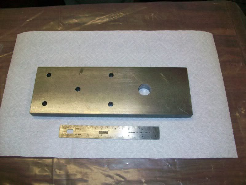
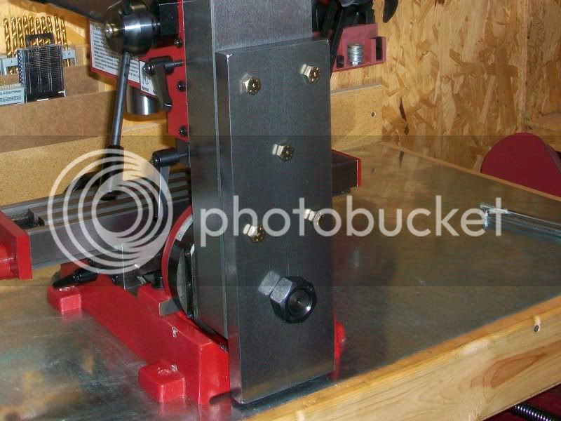
I match-drilled holes for the bolts into the back of the column, tapped them for 3/8" threads, and bolted the plate to the column. The flex was reduced to less than half of what it was, now about +/- .004, but still more than I wanted, and I hadn't fixed the Y-axis tram yet either.
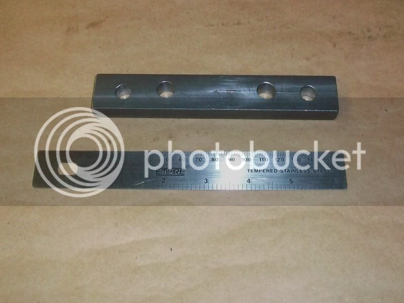
I drilled four holes in a piece of 1/2" thick, 1" wide steel, one at each end for 3/8" bolts, and two near the center for 7/16" bolts. The end holes were far enough apart to clear the edges of the column plate. This would be a pressure plate to push on the bottom of the column plate.
I drilled and tapped holes into the base of the mill itself to match the 3/8" outside holes in the pressure plate, and drilled and tapped through the column plate only for the 7/16" holes, not into be base.
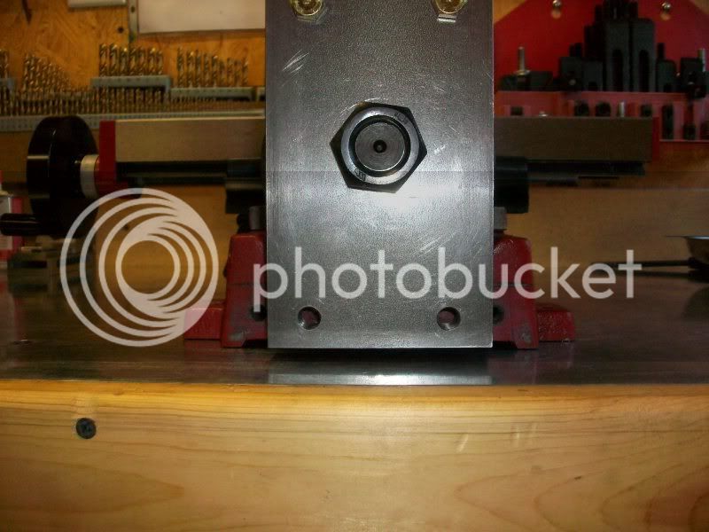
I bolted the pressure plate to the base of the mill with the outside bolts and tightened them until the column was pulled in enough to tilt the column back and eliminate the .004 Y-axis tram error. I then inserted 7/16" bolts through the center holes and screwed them through the column plate until they were snug against the mill base. With the end bolts pulling on the column, and the middle bolts pushing on the column, the bottom of the column was locked in place and the flex was reduced to about +/- .0015.
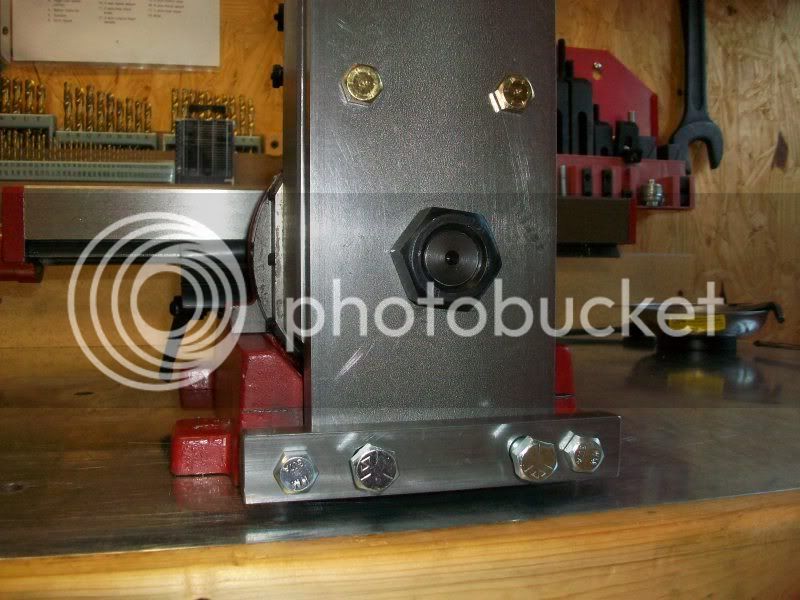
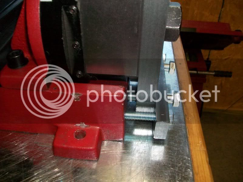
Some final notes:
With the bolts in place, I can no longer rotate the column side-to-side to mill at an angle. I have never used that feature anyway, so it was not a concern to me. Also, my mill was trammed in the X-axis to my satisfaction before I drilled the holes at the bottom of the column plate, but I left plenty of clearance around the 7/16" bolts in the pressure plate to allow some slight angle adjustment for tramming, if necessary.
My mini-mill Y-axis alignment required the bottom of the column to be pulled in toward the base, so the 3/8" outside bolts were tightened first, as evenly as possible to avoid any twist. Then the inside 7/16" bolts were screwed in just tight enough to eliminate any flex. If the required correction was the other way, the center bolts would need to be screwed in first, pushing the bottom of the column away from the base, and then the outside bolts tightened to eliminate any flex.
If I were to do this mod over, I would use a thinner column plate, say 5/8" or 1/2" so the big nut would be sure to grab all of the pivot shaft threads. The 3/4" plate I used just barely allows that. Also, my plate was 12" long. If I were planning to fit my mill with an air spring kit like the one sold by Little Machine Shop, I would shorten to column plate to maybe 10" long so it wouldn't be in the way of the hole in the column required by the kit.
The remaining minor flex in the column assembly is probably due to bending of the pivot shaft and/or the pivot plate. I couldn't think of any practical way to eliminate it entirely.
Drilling into your mill might void any existing warranties. I never had an extended warranty on my mill, so it wasn't a concern.
I think that's about it, thanks for reading.
Rudy
Just how hard did you push? Pushing at the top of the column is produces roughly twice the bending moment if you pushed at the cutter.
What is the max cutting force that this mill can produce?
Has anyone done an analytical study of what you are observing?
I think I will do just that
The column box section is a very good design. It may look "light" compared to the plate you added, but a calculation of it's section modulus (used for deflection calculations) and that of the plate you added will tell a lot.
Has anyone done an analytical study on this deflection?
Just how hard did you push? Pushing at the top of the column is produces roughly twice the bending moment if you pushed at the cutter.
What is the max cutting force that this mill can produce?
Has anyone done an analytical study of what you are observing?
I think I will do just that
The column box section is a very good design. It may look "light" compared to the plate you added, but a calculation of it's section modulus (used for deflection calculations) and that of the plate you added will tell a lot.
Most of the flex isn't coming from the column itself, but from the column to base connection. With the tilting column it's only held down by three bolts at the front edge of the pivot, and the rest of the pivot and column is just left cantilevered out from the base. The plates you see being added to the column are there mainly to provide an additional connection to the base at the back of the column.
On a tilting column mini mill it doesn't take much for at all the deflect the cutting head.
Kfundarek
New Member
Looks great.
Round column I use concrete and tension rod.
Dave
Round column I use concrete and tension rod.
Dave
I did this mod and was pleased with the results. It helped me tram the Y axis which was giving me problems. It also did a good job stiffening things up. Thanks for posting this Rudy!
Last edited:
Similar threads
- Replies
- 3
- Views
- 1K
- Replies
- 74
- Views
- 12K


