Another Radial - this time 18 Cylinders

Home Model Engine Machinist Forum

Help Support Home Model Engine Machinist Forum:

This site may earn a commission from merchant affiliate links, including eBay, Amazon, and others.
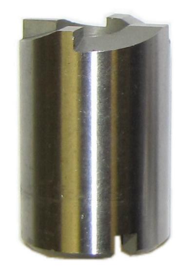
Why not use or make a spark plug seat cutter? http://www.timesert.com/html/howtosp.html This method looks simple enough. You probably need to make on for M10 though.

WasherClean001.jpg


Greg
 
Greg,
Yeah, that was the first thing I tried with my shop made piloted cutter and lap. The one in your picture looks like it might be better suited, though. The chamfer's undercut was so deep that I don't think my .01" deep re-cut was probably deep enough. -Terry
 
I returned to assembling and testing the head/cylinder pairs. My little spark plug diversion spooked me, and so I put off the flange drilling until all the pairs were completed and the dust was allowed to settle. Then I drilled them all in one final operation. For extra measure I increased the head tightening torque from 35 to 40 ft.-lbs, and I went back and re-torqued the already finished assemblies. I eventually modified all the heads with the JB Welded re-surfacing washers. The leak-downs of the first two assemblies that had passed with passable numbers before I discovered the spark plug air leak actually improved 2X after the washers were added. It's likely that all my heads would have leaked to some degree without the modification.
My leaky plug experience got me even more curious about the maximum number of torqued installs the plugs I'm using can receive and still retain their ability to seal. I measured the leak-downs of each of my assemblies using my o-ringed test plug and also a single standard NGK. I recorded the two leak-down times for comparison as well as the number of installs accumulated on the NGK. After 30 installs I could still see no statistical difference between the readings obtained using the two plugs.
Plug install life is worth a consideration with this engine since the usual recommendation on a model radial is to remove the plugs from the lower cylinders after running so oil seeping into the combustion chamber can drain out without causing hydrolock. As I found out, it takes about three weeks for the 40 wt. crankcase oil in my H-9 to find its way past the rings and into the combustion chambers of the lower two cylinders. Evidently the oil seeps through the ring gaps and piston groove side wall clearances.
Out of 80 piston rings that I light-tested during assembly, 11 failed. In all these cases there was only a minor sliver of leakage in random spots with respect to the gap. In one or two instances it might even have been my imagination. The rejects were likely due to circularity errors in the starting blanks. My notes show that the batch that contained nearly all the rejects came from two blanks I had used that contained .0003" circularity errors near their ends.
I ended up with six assemblies that had no measurable leak-down, and I used one of them to check out my shop-made compression gauge. I found and fixed an o-ring leak that it has probably had ever since I made it. I made this particular gauge during my H-9 build with the goal of creating one that could be installed in a tight location where the face might not be visible while cranking over the engine. The central part of the gauge contains a check valve from a tire pressure gauge. I added a 10 mm threaded nose and a miniature pressure readout on either end while being especially careful to minimize the gauge's own internal volume between the input and the check valve. Since model engines have relatively tiny combustion chambers, it's important for a compression gauge to add as little additional volume to the cylinder under test as possible or the compression numbers will be low. I also made sure the gauge can be screwed into the head to about the same depth as the spark plug body.
The flange drilling went smoothly. The drilling fixture worked well, and the plastic cling wrap did its job of protecting the assemblies from the chips. Eight studs were temporarily installed in one the crankcase cylinder locations, and each assembly was trial fitted in place along with an intake tube after it was drilled. When completed, I finally had 24 completely finished and tested head/cylinder pairs with leak-down rates ranging from zero to a maximum of 1.3 psi per second when measured at 75 psi. I also had 23 pistons whose installed rings had all been individually light tested and showed no leakage.
Now it's time to blow a year's dust off my stacks of boxed and bagged finished parts and get on with the final assembly. I think the next step will be to install the crankshaft and oil pump in the crankcase and then verify proper oil flow through the engine and to all the bearings. -Terry

661.jpg


662.jpg


663.jpg


664.jpg


665.jpg
 
Final assembly of the multi-piece crankshaft into the multi-section crankcase is a bit tricky but do-able using a procedure I developed last year while designing those parts. The rear crankshaft section with its crank pin and installed master rod was maneuvered through the front of the rear crankcase section while the rear main bearing was simultaneously inserted into the rear of the rear crankcase section. The two met up inside with the master rod sticking out through cylinder hole number one. The rear main bearing was then bolted in place. The eight slave rods were next installed on the master rod hub by feeding them through the other eight cylinder holes. A simple shop-made tool was used to guide and insert the slave rod pins through the front of the crankcase and into the master rod assembly. This tool was also used to orient the pins so the milled flats on their ends aligned with the pair of 2-56 socket head set screws in the master rod assembly that are used to secure them in place. These screws are accessible through the cylinder holes and were tightened using a standard hex key. The front cheek was then slipped onto the crank pin using a temporary alignment rod inserted through alignment holes in the cheek pair, and then its pinch screw was tightened to 20 in-lbs. I used high strength 6-32 alloy SHCS's for the clamp screws that I had previously tested to failure at 30 in-lbs. This front cheek of the rear crankshaft section contains the female side of the square slip drive.
The center main bearing containing the pre-assembled and tested oil pumps was next installed in the front of the rear crankcase section. An o-ring was added to seal the sump pick-up to the scavenger pump inlet. The oil feed tubes were temporarily installed into the sides of the rear crankcase section where they also screw into the oil pump housing. This step insured the oil pump/center main bearing assembly was properly oriented in the crankcase before finally bolting it in place.
The short crankshaft center section with its installed crank pin and the male side of the square slip drive was then inserted through the oil pump and center main bearing and into the mating socket in the rear crankshaft section. The front master rod was slipped onto the crank pin of the short center crankshaft section and maneuvered to stick through cylinder hole number ten of the front crankcase section. All this was done while the front crankcase section was being stacked onto the rear crankcase section. The front slave rods were installed on the front master rod assembly just as the rear rods were installed on the rear master rod. The cheek of the remaining front crankshaft section was then aligned with its mate, again using a temporary alignment rod, and then its clamp screw was tightened to 20 in-lbs.
At this point the crankshaft assembly was complete, and it turned smoothly with no tight spots just as it did a year ago. As discussed in the early posts dealing with the crankshaft design, dowel pin keys were captured by the tightened pinch screws on all four cheeks. These keys prevent the cheeks from rotating on their crank pins and insure the crankshaft is held in perfect alignment under the torque expected from this engine.
Operation of the pressurized oiling system was verified by using a syringe to inject oil into the intake feed tube while manually rotating the crankshaft counterclockwise. After a few revolutions, oil could be seen seeping from all the bearings. In this engine, oil is pumped into the center section of the crankshaft and forced to flow toward the front and rear of the engine where it lubricates both master rod bearings as well as the center, front, and rear main bearings. Oil seeping from the front and rear rear main bearings splash lubricates the moving parts of the front and rear cam assemblies. An o-ringed seal plate that will be installed later prevents oil from the rear main bearing entering the fuel plenum under the rear cover.
Oil is pumped through the square drive slip connection in order to reach the front of the engine. This precision slip fit connection is, itself, lubricated by its own minor seepage. Windage provides cylinder wall and slave rod lubrication. In the dry sump system of this engine the return oil flows through deep return channels milled in the two crankcase sections and into the sump. The scavenger pump returns the oil from the sump to an exterior oil tank where it is recycled through the engine by the oil pump. A variable flow restrictor will eventually be added to regulate the flow of oil into the engine so the scavenger pump is not overwhelmed while trying to empty the sump. The scavenging system was tested by filling the sump with oil and again manually rotating the crankshaft counterclockwise. After a few revolutions, oil began flowing out of the scavenger return feed tube and continued until the sump was empty.
So far, all is working as expected. The next step is to install and time the front and rear cam assemblies and generate the valve timing events diagrams for the two cylinder banks. - Terry

666.jpg


667.jpg


668.jpg


669.jpg


670.jpg


671.jpg


672.jpg


673.jpg


674.jpg


675.jpg


676.jpg


678.jpg


679.jpg
 
WOW!
gbritnell
 
And another WOW And another WOW And another WOW

I've been following this all along, but there hasn't been much I could say. Congratulations and thank you for your very good explanations and photos and diagrams.

I'll never even aspire to your level, I work too slowly and life keeps getting in the way, but I really like to watch this and I have learned some things about engineering that may be useful. You are an excellent teacher as well as an excellent engineer and designer.


--ShopShoe
 
It's really an amazing piece of work. Can we have some sort of size reference in one photo when you post again.

Paul.
 
Thanks, everyone for your kind comments.
Swifty: In the last photo of my last post with the engine mounted on the stand and resting horizontally, the engine measures 12 inches long between the end of the rear cover and the end of the front crankshaft. - Terry
 
Unlike V-engines, radials seem to have adopted a consistent cylinder numbering system. Double-row radial engine cylinders are numbered clockwise when viewed from the rear of the engine. Cylinder number 1 is at the top of the rear row. Cylinder number 2 is the first one clockwise from number 1, but it is located in the front row. Cylinder number 3 is the next one clockwise from number 2, but it is located in the rear row. All odd-numbered cylinders are located in the rear row, and all even-numbered cylinders are located in the front row. Cylinder number 10 is at the bottom of the front row.
In a radial engine the firing order follows a pattern that allows the firing impulses to continually follow the motion of the crank during its rotation. In a double-row radial engine, the firing order is a bit complicated. The firing order is such that a firing impulse occurring in a cylinder in one row is never immediately followed by a firing impulse occurring in a cylinder of the same row.
An easy technique for figuring the firing order of an 18-cylinder, double-row radial engine is to start with any number from 1 to 18, and then either add 11 or subtract 7 (in radial parlance these are called the firing order numbers), depending upon which gives an answer between 1 and 18. For example, beginning with cylinder 1, add 11 to get a result of 12. Then, because 11 cannot be added to 12 since the total would be greater than 18, subtract 7 to get a result of 5. Add 11 to 5 to get 16. Subtract 7 from 16 to get 9. Subtract 7 from 9 and the result is 2. Add 11 to 2 and the result is 13, and then continue this process for 18 cylinders. The resulting firing order is [1]-12-5-16-9-2-13-6-17-[10]-3-14-7-18-11-4-15-8. One cylinder fires every 40 degrees of crankshaft rotation.
The cams are timed to the crankshaft by focusing on the TDC events of the two cylinders containing the master rods i.e. cylinder 1 for the rear cam and cylinder 10 for the front cam. Even though these two cylinders oppose one other, their also opposing crank pin throws mean their pistons will reach TDC at exactly the same time.
In a four stroke engine each piston hits TDC twice within its 4-stroke cycle: once during the transition from its exhaust stroke to its intake stroke, and once during firing - the transition from its compression stroke to its power stroke. After the cams have been properly timed, the TDC's of cylinders 1 and 10 will occur on opposite halves of the 4-stroke cycle. That is, while cylinder 1 is transitioning from exhaust to intake, cylinder 10 will be firing.
However, to simplify the timing process, each cam will actually be timed using the TDC in the first half of the 4-stroke cycle. In this first half cycle, where the exhaust stroke is transitioning to the intake stroke, the flanks of the cam's lobes are adjacent, and the center between them is easily determined. After the rear cam has been timed, though, the crankshaft must be rotated 360 degrees before applying the same timing process to the front cam. This is necessary so that, after timing, cylinders 1 and 10 wind up on opposite halves of the engine's 4-stroke cycle as required by the engine's firing order.
The rear cam was timed first. A rear row head/cylinder assembly was temporarily installed on the crankcase in position number 1. A spare H-9 piston without rings was temporarily installed on the master rod, and a pair of tappets were inserted into the tappet bushings for this cylinder. A shop-made adapter was threaded into the spark plug hole of the cylinder so a dial indicator resting against the piston crown could indicate TDC. Two additional dial indicators were set up on the tappets and zeroed out while the tappets were resting on the base of the cam ring.
With the piston at TDC and the jackshaft temporarily removed, the cam ring was manually rotated until it was centered between the exhaust closing event and the intake opening event as determined by the dial indicators on the tappets. The resolution of the gear train is actually fairly coarse, but the teeth of the two gears on the jackshaft are randomly aligned. And so, with patience, a position can usually be found that maintains the center between the lobes within a few degrees after the jackshaft is re-inserted. After being satisfied with the result, the o-ringed rear seal plate was then installed followed by the impeller.
A degree wheel was installed on the crankshaft, and the timing of the valve events was measured at a .010" tappet lift. The intake and exhaust durations were measured at 208 and 235 degrees, respectively. The intake lobe center was located at 107 degrees ATDC and the exhaust lobe center at 114 degrees BTDC. The cams in this engine are very mild, with an almost negligible 5 degrees of overlap 'near' TDC.
After rotating the crankshaft 360 degrees, a similar process was followed for the front cam assembly using cylinder number 10. After completion, the front cover was installed.
The next step is to install the head/cylinder assemblies as well as the intake/exhaust tube pairs. Terry
680.jpg


681.jpg


682.jpg


683.jpg


684.jpg


685.jpg


686.jpg


687.jpg


688.jpg
 
Hi Terry
Very impressive.
I really like the 11-7 rule for determining firing order. But I have a question ? Will that work on your next build, the 3 bank 27 cylinder ? :)

Scott
 
Construction continued with Loctiting 164 4-40 cylinder flange studs around the perimeter of the crankcase. I used 1/2" long stainless steel socket head set screws instead of making a huge batch of custom studs. Each stud eventually receives a washer, lock washer, and nut - all of them small pattern parts. I trial-fitted the head assemblies down over the studs in a few tight areas near the sump and oil feed tubes to make sure there were no surprises ahead.
Since I hadn't yet finalized how I was going to splice the long intake tubes, it was now time to decide. After a lot of back-and-forth I settled on a short length of Kynar shrink tubing covered by a cosmetic stainless sleeve. I had been also toying with an option to insert a thin Viton o-ring between the ends of the tubes for extra sealing insurance before shrinking down the Kynar. But, being concerned the o-ring might become dislodged and find its way into the intake, I decided to leave it out. I used a thin (.015") slitting saw to cut the intake tubes on the twelve remaining tube assemblies in order to leave a minimum gap between the ends. Just to make things even more difficult for myself, I turned the batch of stainless steel sleeves with very thin (.010") walls. The i.d.'s of the sleeves were reamed for a very snug fit over the Kynar. In fact, I had to make up a tiny rubber strap wrench to roll it into final position.
After installing my first assembly, I learned that even though the clearance notch I had milled in the side of the rear row heads wrapped nicely around the spliced intake tube, I hadn't fully taken the studs into account. There was a slight interference with one the fins just below the notch while the cylinder was being inserted into position over its studs. This interference would have increased the difficulty involved with removing cylinders later, if necessary; and so I set up a fixture on my manual mill to remove an additional bit of material from each of the twelve rear row heads.
Then, after installing the third pair of heads I began having second thoughts about two things I was doing. The first was how I was supporting the engine while installing the cylinders. Tightening the flange nuts on the 'easy' top cylinders had been an exercise in patience on more than half of the studs and required several tiny wrenches, a couple shop-made tools, and lots of re-positioning of the engine. Looking ahead, the studs on the bottom six cylinders, especially around the sump area, look nearly impossible to access with the engine mounted on its display stand. The engine already weighs nearly 20 pounds, and it's getting heavier and more awkward to deal with. I made up two simple work stands to support the engine vertically on either end, but it appears the bottom flange studs will still be too difficult to access without an ability to continually reposition the engine as I had been doing on the top cylinders. What I really need is a rotisserie engine stand in order to safely finish the assembly.
My second concern was with the gasket material I was using for the exhaust flanges. I made these gaskets from some no-longer available automotive gasket material that I had purchased from a local auto parts store several years ago. This was the same material I heat tested during my JB Weld evaluation and it's also the same material I used for the exhaust flanges on my H-9. What concerned me was the very close fit of my gaskets in the deep exhaust flange pockets in my T-18 heads. I saw this material adhere to the stainless washers in my JB Weld heat test. If the same thing happens in the pockets of my heads, it will be very difficult to remove the flanges and cleanly replace the gaskets if the need ever arises. I disassembled one of the exhausts from my H-9 build; and, sure enough, one side of the gasket was stuck fast to the exhaust flange in that engine. This adhesion isn't a problem in the H-9, though, since the exhaust flanges simply slide into place from the top and do not rest in pocketed recesses as they do in my T-18 heads. An old H-9 gasket is easily scraped away and replaced, but this would not be the case in these heads. Furthermore, the discoloration I saw on the H-9 gaskets told me they had been running at close to the maximum 250F temperature rating of this material.
So, I ordered a more exotic 700F Aramid sheet material in order to re-make my exhaust flange gaskets. Unfortunately, I'll have to disassemble nearly two days work when I replace the six already-installed gaskets.
While I'm waiting on the new gasket material I'm going to make a rotisserie engine stand that will be better suited for supporting the engine for its final assembly. - Terry

689.jpg


690.jpg


691.jpg


692.jpg


693.jpg


694.jpg
 
Hi Terry
Again WOW !

Those flange nuts do look like they are lots of fun. Have you considered a flexible shaft nut driver to get them started? I have a 1/4" drive one that is joined to the handle by a piece of aircraft cable. I really works well for getting things started. Maybe a smaller one could be made up , with a thin wall socket and a piece of 1/8" cable. It might help.

Scott

nut driver.jpg
 
I have been watching the PBS/Ken Burns series on the Roosevelts this week. One thing mentioned was that during the war Ford had a production line that could turn out a B24 bomber every hour, each with 4 14-cylinder engines (2 rows of 7). Each airplane had about 1.5 million parts. Following this build shows how incredible that production was back in the 1940s.

Another interesting tidbit was the American auto manufactures produced a total of about 150 cars during all of the US involvement in WWII.
 
Scott,
Here's the problem I'm dealing with. The closeness of nut to the cylinder wall will only allow my highly modified closed end wrench to get around it. Then there is the tapered profile of the cylinder that forces me to come in from the side. I've been threading the nut on the little tool that I made and then coming in from the side and then threading the nut off the tool and onto the stud with a tiny probe. This works pretty well, but tightening the nuts that last half turn requires several different shaped open end wrenches and lots of re-positioning of the engine. - Terry

695.jpg


696.jpg
 
Yup, I saw/heard that also. I wondered how many of those 1.5 million parts were rivets.

Some time ago I was thinking that Terry's work on his engine was something it normally took an entire company to do. And which they could not do as well.

-Bill

I have been watching the PBS/Ken Burns series on the Roosevelts this week. One thing mentioned was that during the war Ford had a production line that could turn out a B24 bomber every hour, each with 4 14-cylinder engines (2 rows of 7). Each airplane had about 1.5 million parts. Following this build shows how incredible that production was back in the 1940s.

Another interesting tidbit was the American auto manufactures produced a total of about 150 cars during all of the US involvement in WWII.
 
After deciding that I was going to make an engine stand, my first inclination was to torch-cut the parts and weld up something substantial and quick. It seems I don't know how to work that way anymore, and so I ended up back in SolidWorks designing something that would fit both my T-18 and H-9 and maybe even my next project. I added a requirement that the stand has to be capable of holding either fully assembled engine including the distributors and carburetors. That feature will allow it to be used for routine maintenance on the engines including valve lash adjustments and compression checks. These chores were going to be very difficult to perform on the bottom six cylinders of this engine while on its display/running stand.
I started by milling a mounting ring from 3/8" steel plate. I used the code I'd already developed for the exact same ring I made for the display stand. I cut out three new support arms from 5/16" steel and welded them to the three mounting tabs on the ring. The other ends were radially welded to the outer diameter of a short length of 1.25" o.d. d.o.m. tubing. The base of the stand was torch cut from a 1/4" steel plate. The end of a short piece of 1" by 2" rectangular tubing was then welded to the baseplate to create the stand's upright column. The stand was completed by welding a short length of 1.25" i.d. d.o.m. tubing horizontally to the top of the column. The tube on the mounting ring fits perfectly inside the tube on the column so the mounting ring can be easily rotated. A 1/4"-20 grub screw was added to the tube on the upright in order to secure the mounting ring so the engine's crankshaft can be safely spun while the engine is mounted on the stand.
The wooden vertical stand that I previously made is used to temporarily support the engine while the display/running stand and rotisserie's mounting ring are exchanged. This bit of extravagance will be welcomed later as the engine grows in weight and awkwardness. After mounting the engine it was immediately obvious that a rotisserie stand is an absolute must for assembling this engine. If it weren't for the ignition wiring and the oil and fuel lines I'd integrate this feature into the final display/running stand.
The new gasket material has arrived, and so my next steps are to cut out the new exhaust flange gaskets, replace the old ones already installed, and then continue on with the engine assembly on my new stand. -Terry

697.jpg


698.jpg


699.jpg


700.jpg


701.jpg


702.jpg


703.jpg
 
After this work of art I can't imagine how you could top this Terry
 

Latest posts

Back
Top