Well it is never as interesting when a post is made in bulk like this but I wanted to post my Webster Engine progress on HMEM. I think some of you may have been following this on madmodder.
I decided on the Webster as a simple build (I use the word simple loosely) I started to get materials collected. I snagged a lot of aluminium plate from the scrap heap several months ago and finally I`ve been lucky in the fact that I`ve got pretty much all the sizes I`ll need.

Unfortunately I did not have the cast iron or leaded steel for the cylinder so I purchased that

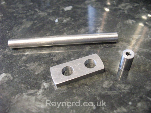
I`m also changing from the plans and will be using 8mm silver steel for the crank rather than the imperial .313" that is stated. I`m also going to run the crank in bearings rather than brass bushes as stated and these arrived last week:

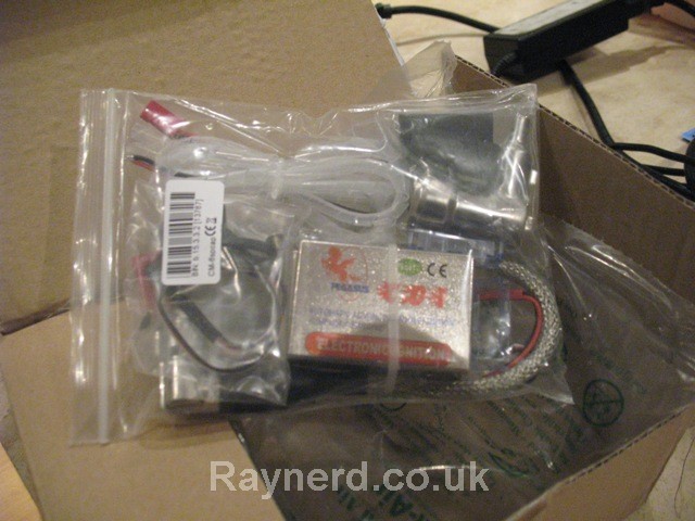
I also ordered a small NPK spark plug that cost £3 on ebay but I`ll need a M10 x 1.0 tap which is annoying, my M10 taps are all M10 x1.25mm.
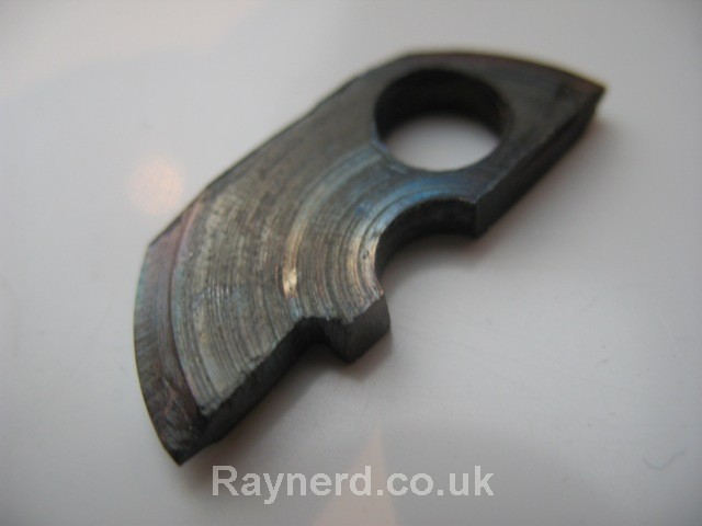
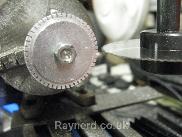
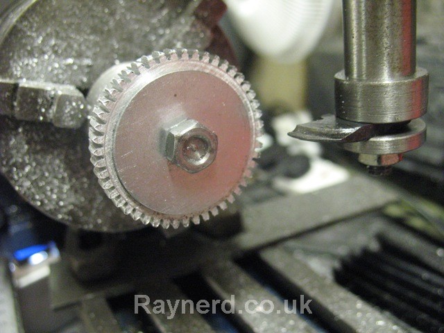
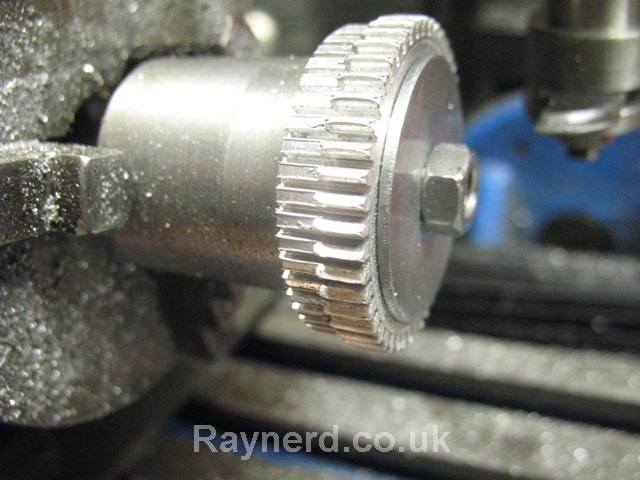
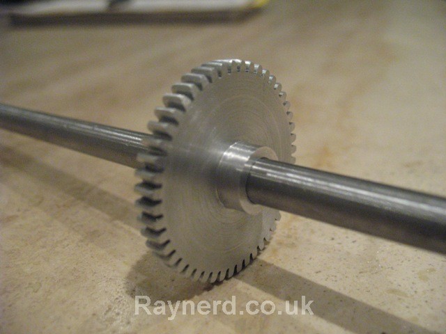
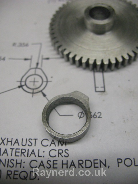
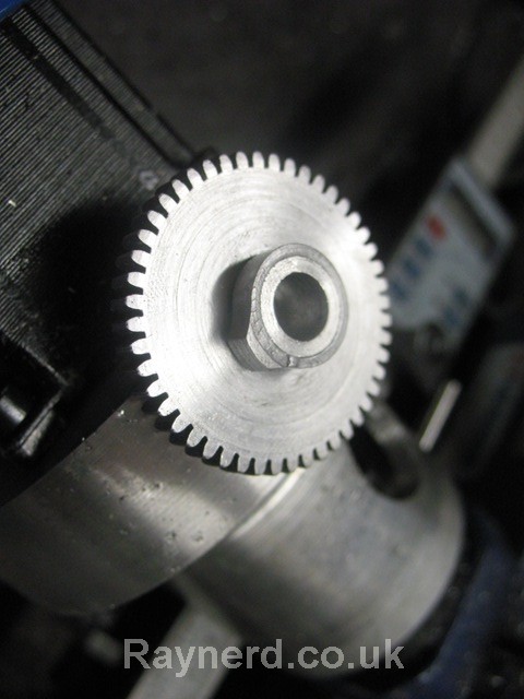
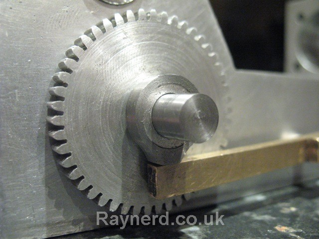
Then it comes to the gears!! I`m going to try and cut the gears. Thankfully in my efforts in my continuing clock build I`ve attempted several gears so I`m quite comfortable about giving these a crack. Involute spur gear cutters are MUCH cheaper, at about £20 a cutter than Cycloidal clock wheel (gear) cutters which sell for about £60-80 a cutter! Despite this fact, I`m going to try and make my own cutter again using the methods and calculations provided by John Stevenson on the web. I`ve done all the calculations, they are here:
http://www.raynerd.co.uk/?p=970
Well after all that thinking :med: :coffee: :scratch:... time for some chips :dremel:.
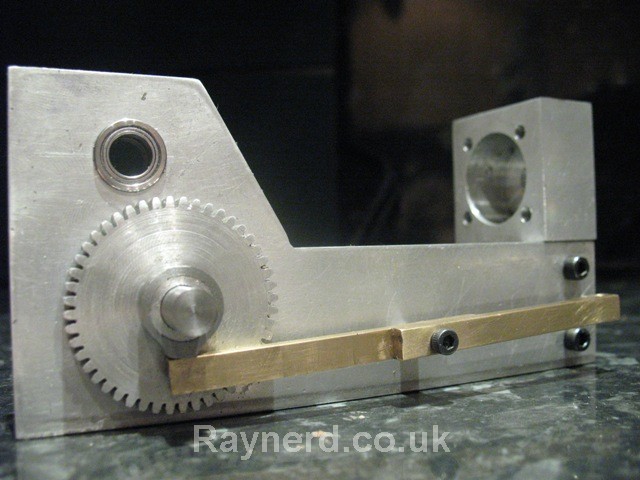
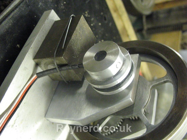
It always takes me bloody ages to just cut the pieces, infact it took me a few nights just to rough out a few pieces from the big sheets of aluminium. Here are the two side supports, the one blued up is to size, the back longer support is just roughed out.

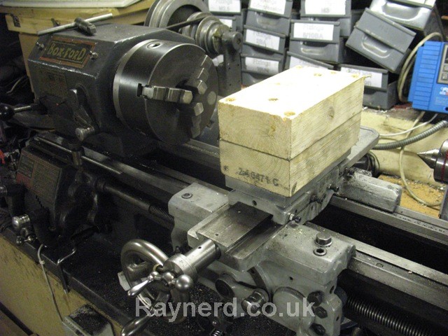
I`m in a bit of a pickle with regards to the base. I`ve nothing really suitable and can`t afford a piece of ally big enough just for the base of this. I think this piece will do, but it is a little bit thin, then again my plan is to raise the base on pillars so the electrics can go under it.

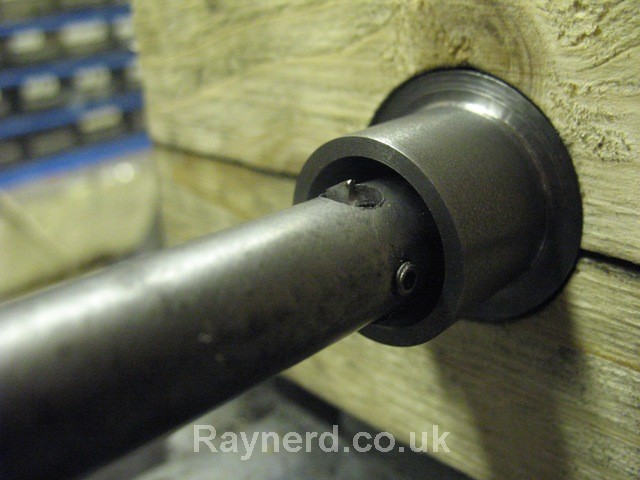
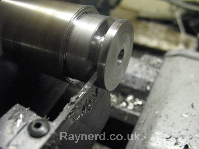
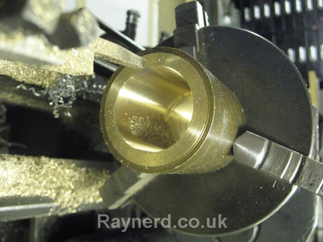
I`ve also been preparing for cutting the cylinder bore which I`m going to do between centres. Lots of good advice was given here:
http://madmodder.net/index.php?topic=4093.0
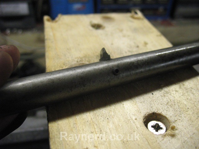
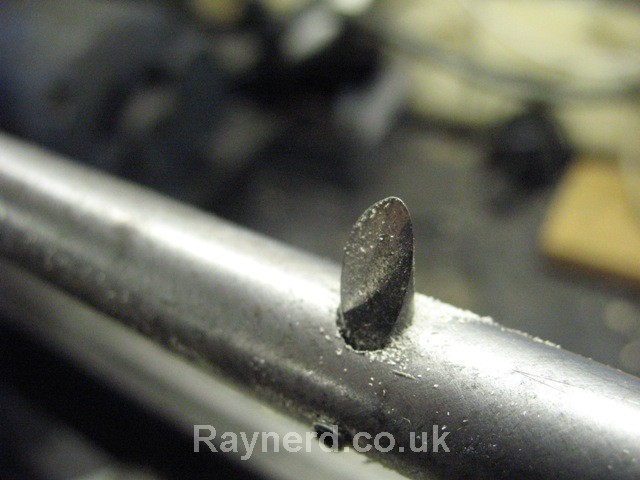
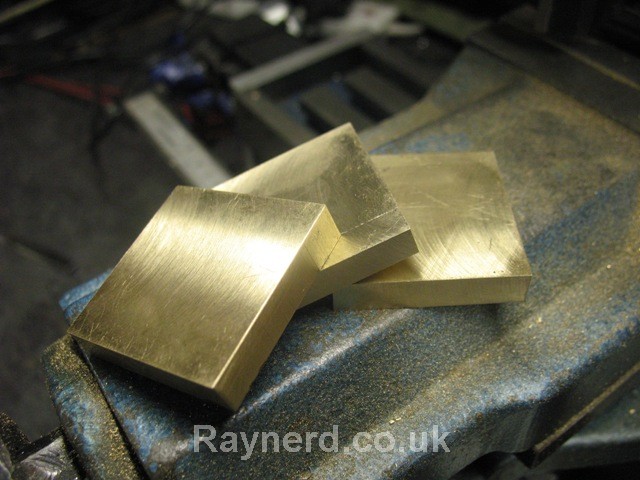
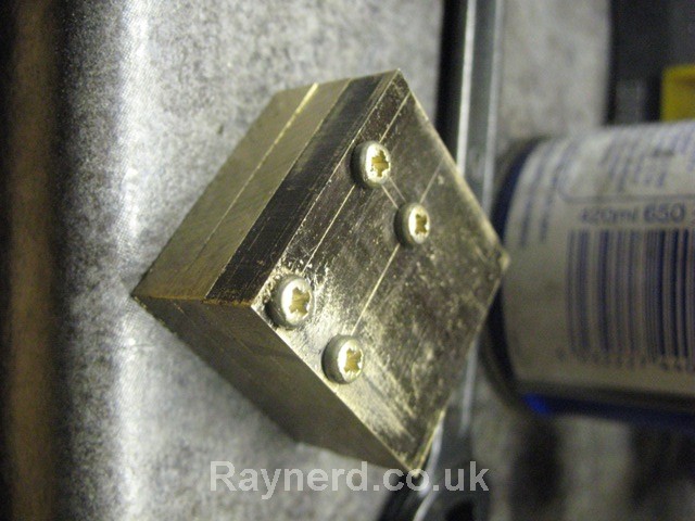
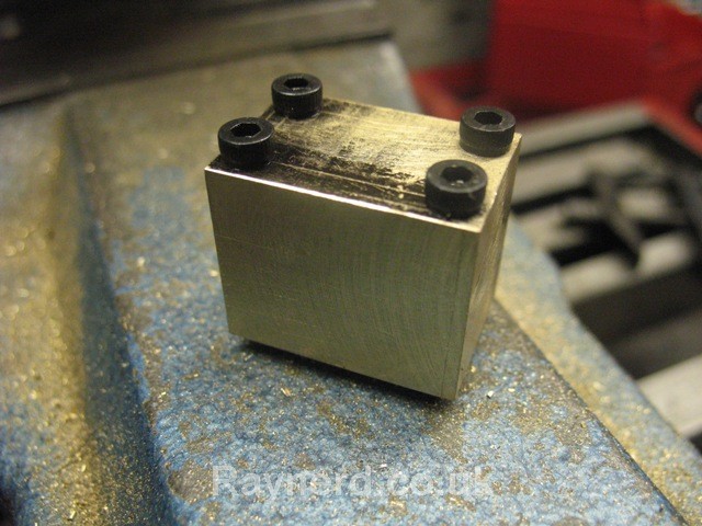
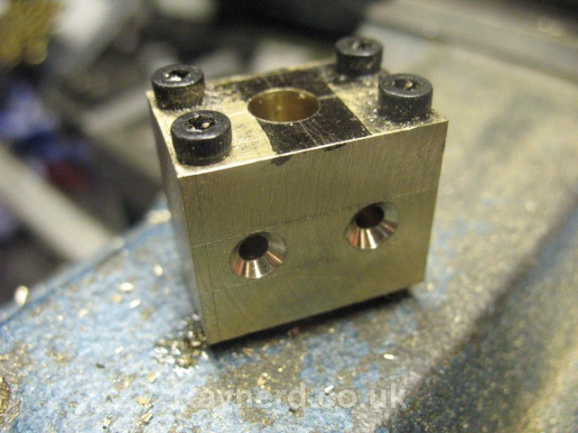
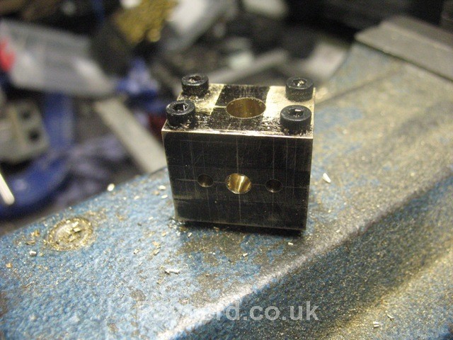
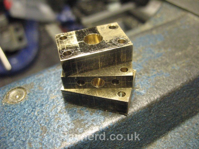
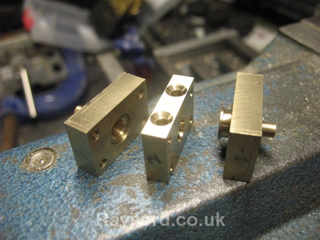
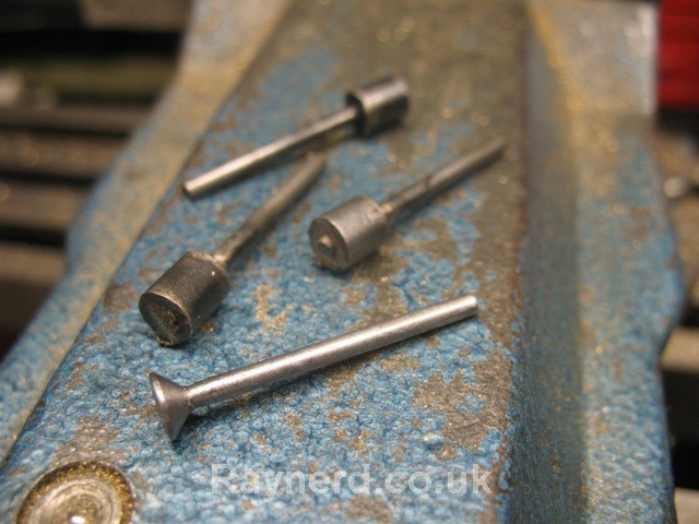
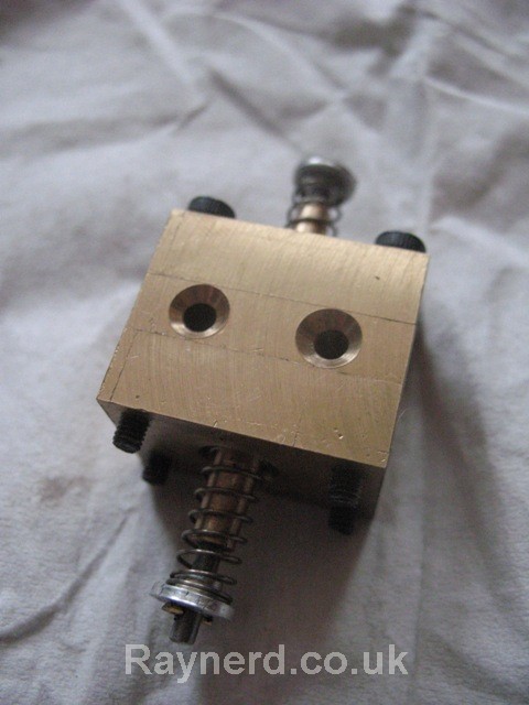
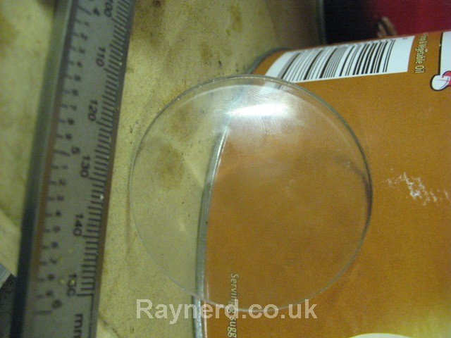
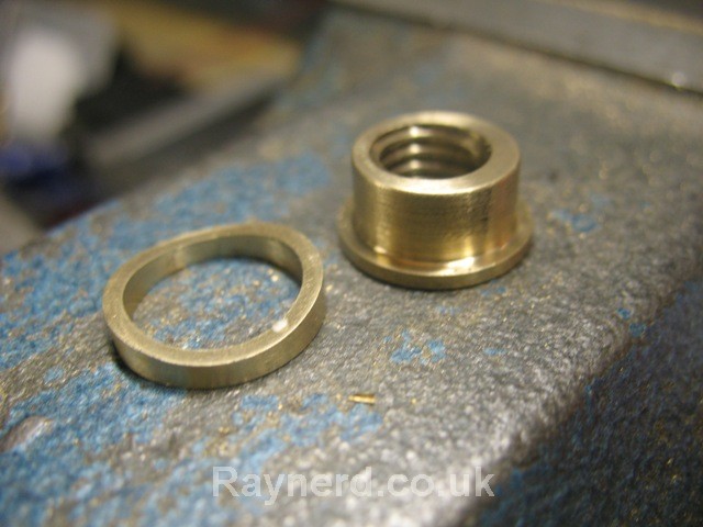
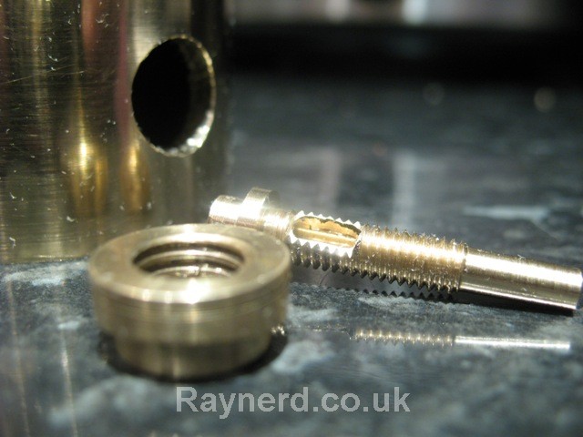
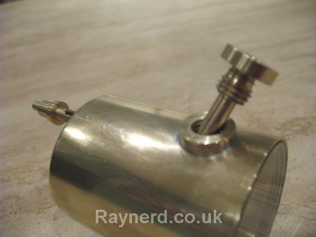
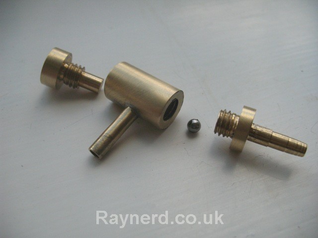
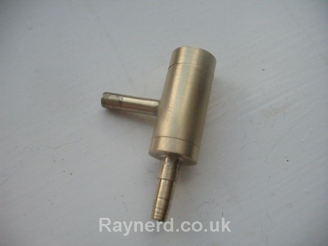
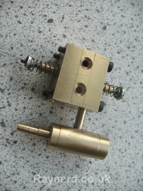
and in preparation I made this bore setting device:
http://www.raynerd.co.uk/?p=992
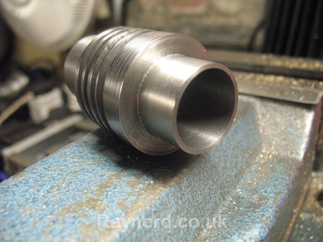
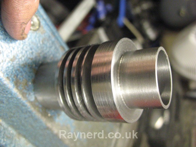
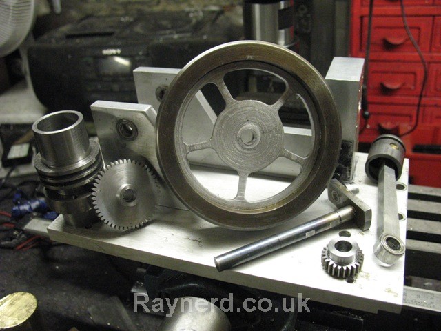
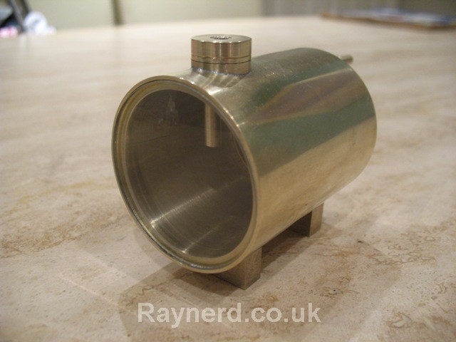
And with so much success, I had to fall over some where!
looking good so far:

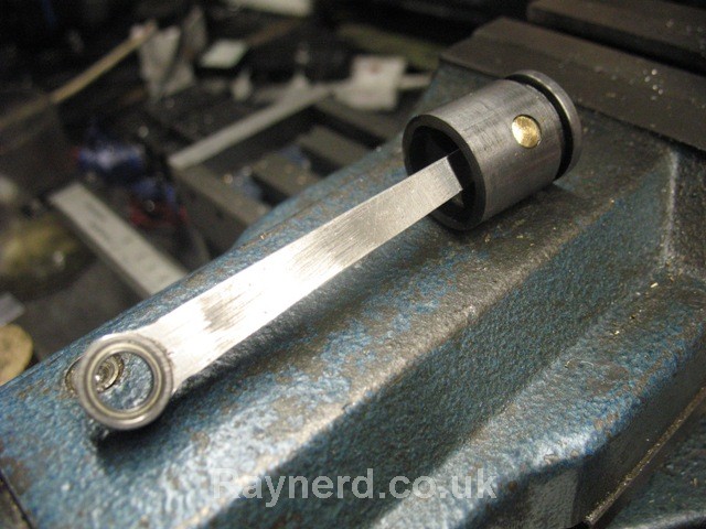
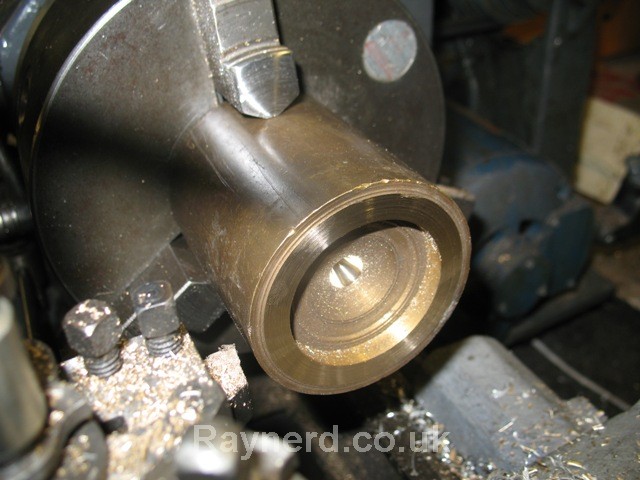
yea... then I thought I could just not show it hence the angle of the photo...but look at the fins
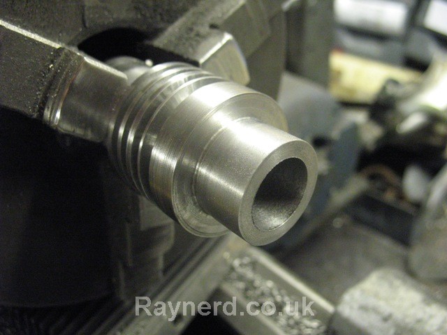
but hey ho! I`m going to go and bore it and hopefully it`ll still run, just the gap between the fins is wrong. Two stupid errors, I misread the plans and then to compound the issue, the work managed to move from the 3 jaw during grooving!!
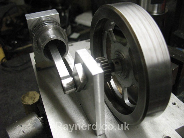
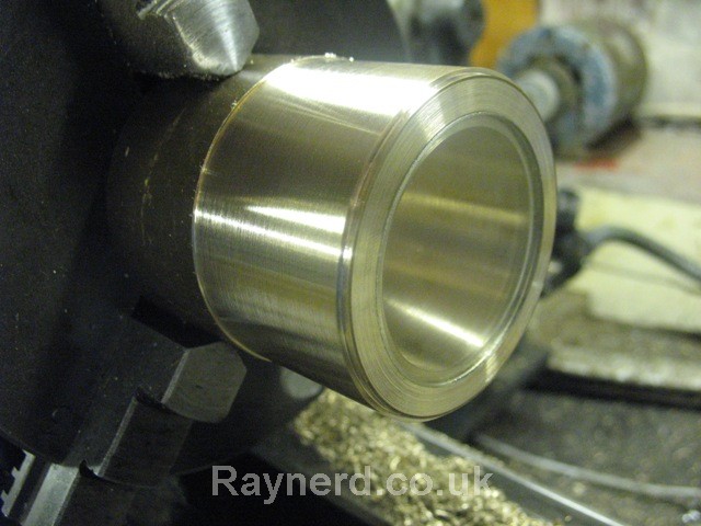
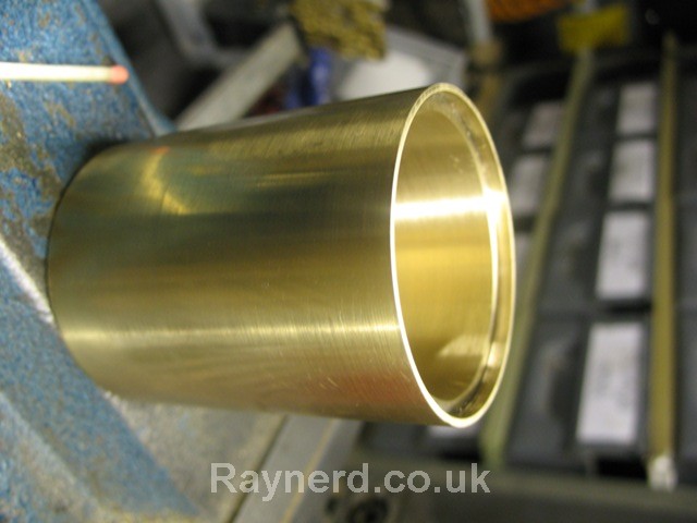
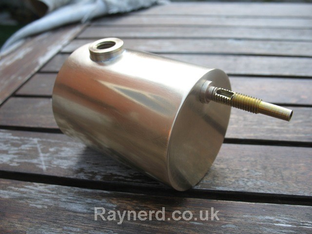
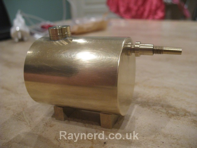
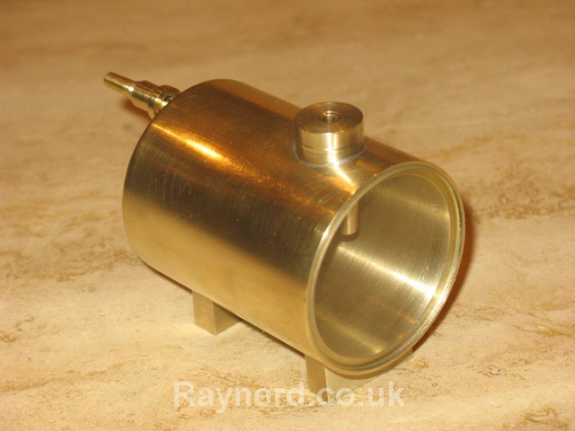
Here is the cylinder with the roughed out cylinder support piece:

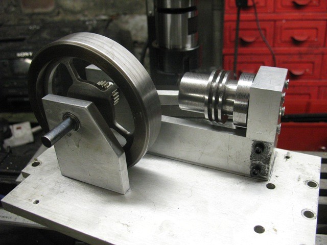
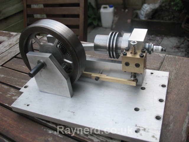
...and that is pretty much where I am up to right now. Next job is to mount the cylinder again for boring between centres.
I decided on the Webster as a simple build (I use the word simple loosely) I started to get materials collected. I snagged a lot of aluminium plate from the scrap heap several months ago and finally I`ve been lucky in the fact that I`ve got pretty much all the sizes I`ll need.
Unfortunately I did not have the cast iron or leaded steel for the cylinder so I purchased that
I`m also changing from the plans and will be using 8mm silver steel for the crank rather than the imperial .313" that is stated. I`m also going to run the crank in bearings rather than brass bushes as stated and these arrived last week:
I also ordered a small NPK spark plug that cost £3 on ebay but I`ll need a M10 x 1.0 tap which is annoying, my M10 taps are all M10 x1.25mm.
Then it comes to the gears!! I`m going to try and cut the gears. Thankfully in my efforts in my continuing clock build I`ve attempted several gears so I`m quite comfortable about giving these a crack. Involute spur gear cutters are MUCH cheaper, at about £20 a cutter than Cycloidal clock wheel (gear) cutters which sell for about £60-80 a cutter! Despite this fact, I`m going to try and make my own cutter again using the methods and calculations provided by John Stevenson on the web. I`ve done all the calculations, they are here:
http://www.raynerd.co.uk/?p=970
Well after all that thinking :med: :coffee: :scratch:... time for some chips :dremel:.
It always takes me bloody ages to just cut the pieces, infact it took me a few nights just to rough out a few pieces from the big sheets of aluminium. Here are the two side supports, the one blued up is to size, the back longer support is just roughed out.
I`m in a bit of a pickle with regards to the base. I`ve nothing really suitable and can`t afford a piece of ally big enough just for the base of this. I think this piece will do, but it is a little bit thin, then again my plan is to raise the base on pillars so the electrics can go under it.
I`ve also been preparing for cutting the cylinder bore which I`m going to do between centres. Lots of good advice was given here:
http://madmodder.net/index.php?topic=4093.0
and in preparation I made this bore setting device:
http://www.raynerd.co.uk/?p=992
And with so much success, I had to fall over some where!
looking good so far:
yea... then I thought I could just not show it hence the angle of the photo...but look at the fins
but hey ho! I`m going to go and bore it and hopefully it`ll still run, just the gap between the fins is wrong. Two stupid errors, I misread the plans and then to compound the issue, the work managed to move from the 3 jaw during grooving!!
Here is the cylinder with the roughed out cylinder support piece:
...and that is pretty much where I am up to right now. Next job is to mount the cylinder again for boring between centres.