


I have a mechanism in which a valve has a sealed shaft running through it. The valve direction of operation is opposite that of the shaft motion. I figure I can do this by using a see-saw type lever acting on a bush incorporated into the shaft. Having looked it over it just seems that its unlikely to work well or easily.
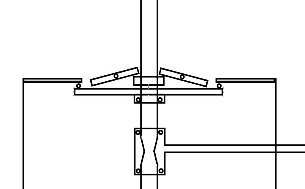
All the circles in the sketch represent oring seals with the exception of the two in the centre of the levers, which represent pivots. The disc has a collar attached underneath which seals to the shaft with an oring.
At the time of opening the main disc valve there is little or no pressure on it, as this has been equalised by the collar further down the shaft venting any pressure difference via the narrower rod section. However the disc needs to be pushed squarely by the pivoted levers and in a fashion that will not cause binding. The disc will close by pressure provided from a light spring not shown in the sketch.
So I guess I'm looking for a better lever arrangement or design which will allow pressure applied to the disk to be equal and square to the direction of movement.
Any thoughts much appreciated.
Best Regards
picclock
