


putputman
Senior Member
- Joined
- Nov 22, 2008
- Messages
- 600
- Reaction score
- 55
This procedure takes some time & effort to begin with but it sure makes life easier for any follow on projects. Consider it if you plan to build many models.
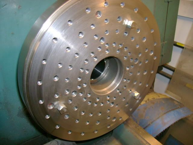
I made a plate with a series of tapped holes and fastened it to my faceplate. This plate comes in handy for many operations. I then inserted three 1/4-20 hex head bolts with a jam nut for a spacer. These were positioned so they would support the flywheel in three places. I then faced them off so they run true with the face plate.
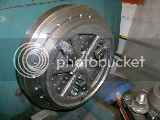
I clamped the flywheel in three places over the bolts. Indicate the O.D. of the flywheel and O.D. of the hub and compromise between the two. Now I am able to face off one side of the flywheel and hub, turn the O.D on both the flywheel & hub, chamfer the inside lip of the flywheel, and bore the I.D. all in one set up.
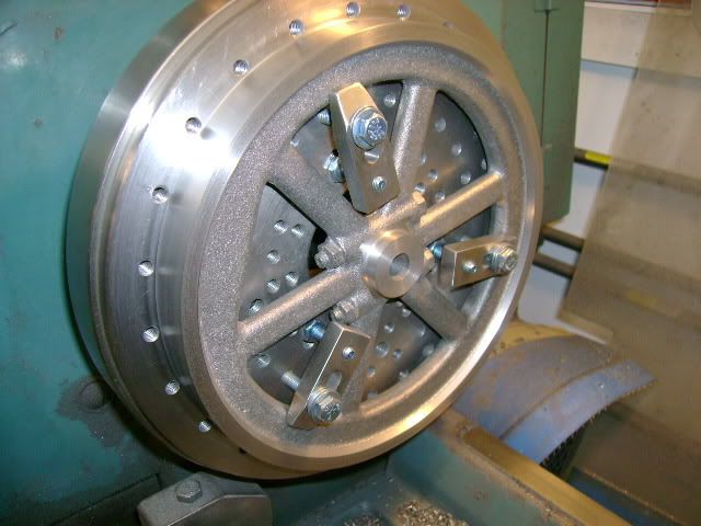
Next I remove the hex bolts and clamp the flywheel directly to the faceplate and indicate the O.D. Then machine the surfaces on that side of the flywheel.
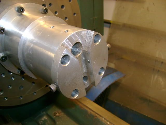
I also use the face plate fixture for turning crankshafts. I made a universal holding fixture that mounts to the face plate.
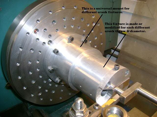
For each differant crank shaft throw or diameter I make or modify a holding fixture. This allows me to hold the crank shaft securely right next to the offset throw and do the turning.
I made a plate with a series of tapped holes and fastened it to my faceplate. This plate comes in handy for many operations. I then inserted three 1/4-20 hex head bolts with a jam nut for a spacer. These were positioned so they would support the flywheel in three places. I then faced them off so they run true with the face plate.
I clamped the flywheel in three places over the bolts. Indicate the O.D. of the flywheel and O.D. of the hub and compromise between the two. Now I am able to face off one side of the flywheel and hub, turn the O.D on both the flywheel & hub, chamfer the inside lip of the flywheel, and bore the I.D. all in one set up.
Next I remove the hex bolts and clamp the flywheel directly to the faceplate and indicate the O.D. Then machine the surfaces on that side of the flywheel.
I also use the face plate fixture for turning crankshafts. I made a universal holding fixture that mounts to the face plate.
For each differant crank shaft throw or diameter I make or modify a holding fixture. This allows me to hold the crank shaft securely right next to the offset throw and do the turning.