Steam engines need them, and if with Stevenson reversing gear you need doubles. Here's what a double eccentric looks like

This particular engine, a stuart triple, needs one in the middle of engine as well as the two ends. As it would be impossible to install in one piece, its made it two halves...a little trickier to make. I included it here because it ends up giving a great cross section of the eccentric. Both of these are about the size of a quarter, 7/8" OD.

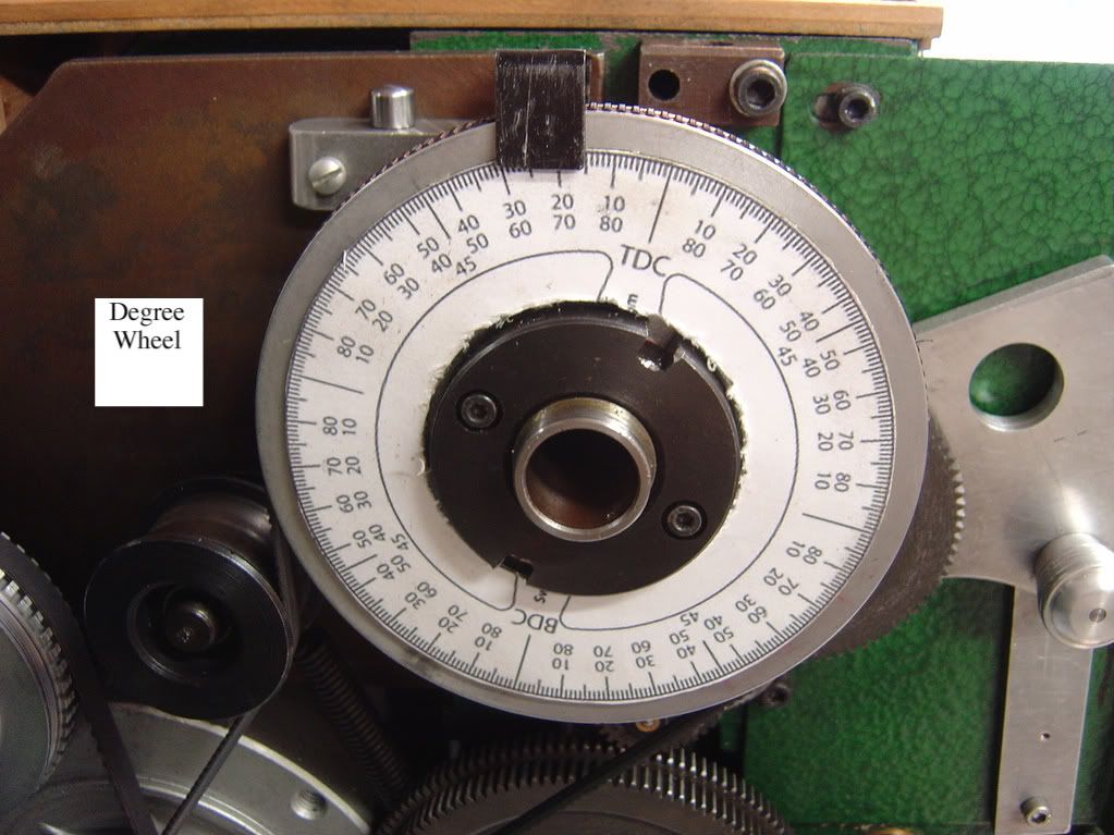
One of the tricky parts is that the part must be turned on three separate axis. Its important that each eccentric is the correct distance from the crank section AND that the angular separation of the two eccentrics is reasonably accurate.
Hilmar referred to an approach published by Tubal Cain. His required levels and protractors to set things up the lathe which always struck me as a bit awkward. There may not be a more revered ME author than Tubal Cain, however I think he mustn't have had a mill at his disposal - if you do here is an alternate method.
In a nut shell, I made an arbor who's endcap accurately fits the bore of the eccentric and has some very small holes spotted exactly on the centres of the crank and the two eccentrics. This way each axis can be positioned in the four jaw.
first, face on both ends and carefully bore the eccentrics to fit the crank
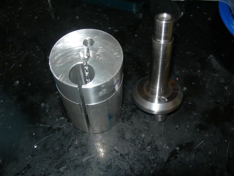
turn the arbor as per pic - be precise. also turn a bolt that also has a section that accurately fits inside the eccentric.
Load the arbor in a vise at the mill, use a V block and accurate square - make sure things are vertical. Indicate the portion of the arbor that goes inside the eccentric.
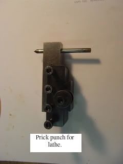
Doing some math from the plans, figure out the X/Y coordinates of each of the three centres. make a small spot drill mark or something a wiggler can pick up.
the arbor is done


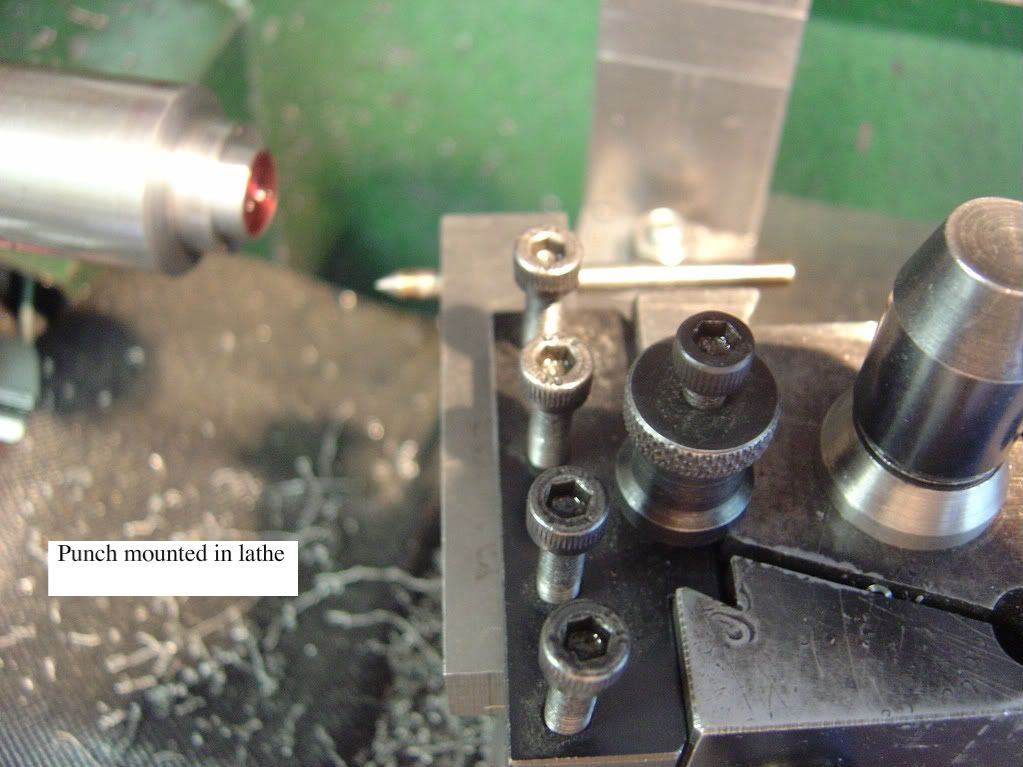
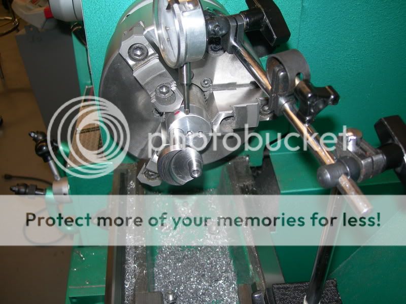
In use, eyeball the alignment of the eccentric and firmly clamp on the arbor with the bolt. Using a wiggler and indicator in the four jaw, in turn, do the lathe work each of the three axis. DO NOT unbolt the arbot until the eccentric is done. Turn at one axis completely, then re indicate to the next and so on.
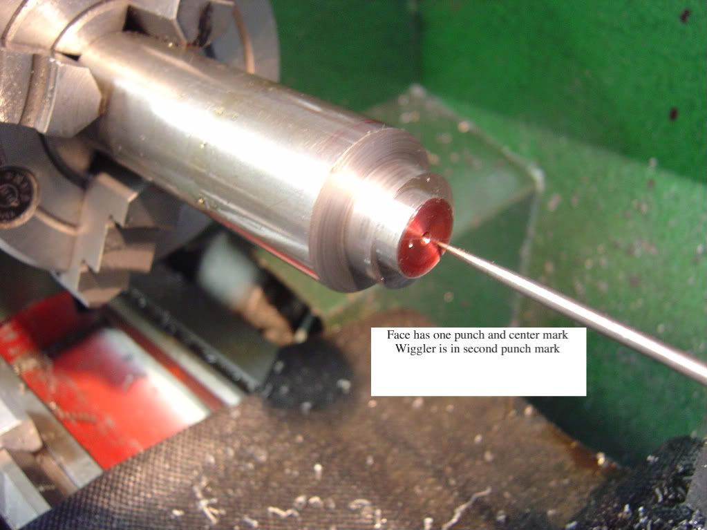
in the pic there are five spots shown - this is because on some engines the angular spacing the eccentrics is different for different cylinders - only three are used for each eccentric
This particular engine, a stuart triple, needs one in the middle of engine as well as the two ends. As it would be impossible to install in one piece, its made it two halves...a little trickier to make. I included it here because it ends up giving a great cross section of the eccentric. Both of these are about the size of a quarter, 7/8" OD.
One of the tricky parts is that the part must be turned on three separate axis. Its important that each eccentric is the correct distance from the crank section AND that the angular separation of the two eccentrics is reasonably accurate.
Hilmar referred to an approach published by Tubal Cain. His required levels and protractors to set things up the lathe which always struck me as a bit awkward. There may not be a more revered ME author than Tubal Cain, however I think he mustn't have had a mill at his disposal - if you do here is an alternate method.
In a nut shell, I made an arbor who's endcap accurately fits the bore of the eccentric and has some very small holes spotted exactly on the centres of the crank and the two eccentrics. This way each axis can be positioned in the four jaw.
first, face on both ends and carefully bore the eccentrics to fit the crank
turn the arbor as per pic - be precise. also turn a bolt that also has a section that accurately fits inside the eccentric.
Load the arbor in a vise at the mill, use a V block and accurate square - make sure things are vertical. Indicate the portion of the arbor that goes inside the eccentric.
Doing some math from the plans, figure out the X/Y coordinates of each of the three centres. make a small spot drill mark or something a wiggler can pick up.
the arbor is done
In use, eyeball the alignment of the eccentric and firmly clamp on the arbor with the bolt. Using a wiggler and indicator in the four jaw, in turn, do the lathe work each of the three axis. DO NOT unbolt the arbot until the eccentric is done. Turn at one axis completely, then re indicate to the next and so on.
in the pic there are five spots shown - this is because on some engines the angular spacing the eccentrics is different for different cylinders - only three are used for each eccentric