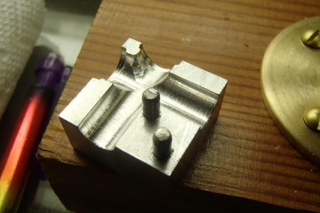
Ok, after I got the two alum blocks cut a little oversize, I rough figured where the pin locations would go I drilled and reamed them, loctited the pins to one side and milled the combination down to make a nice square block, as per the sketch metal butcher posted in his build.
http://www.homemodelenginemachinist.com/f25/tapping-model-pipe-elbows-12911/
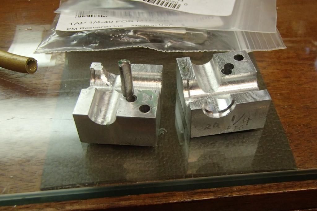
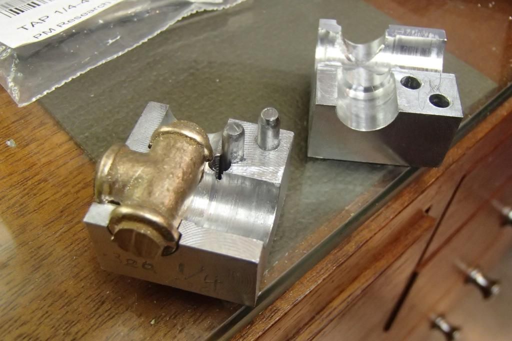
When I laid out the pins I thought I left enough room for the fitting bores, but, unfortunately, I was wrong and the top hole was going to interfere with the 5/16" hole, so I put it aside and started over. I think that this block might be OK for a 3/16" fitting.
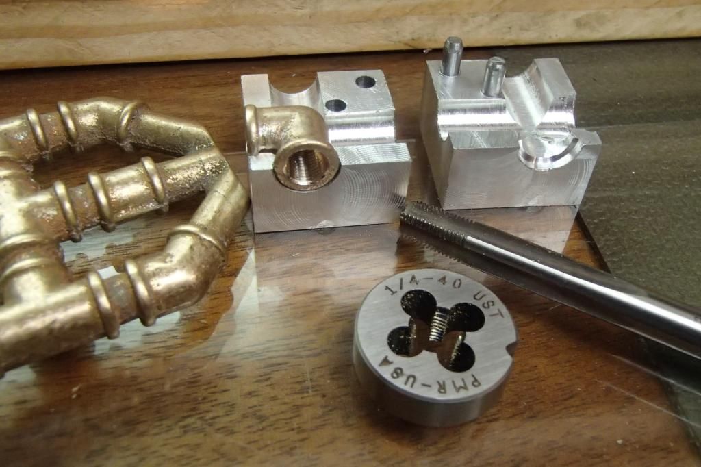
New block made I drilled the 5/16 cross holes and made the two shallowest counter bores and tried the casting. Not a bad fit with a little tweaking. I also noticed that it looked like the bottom c'bore would bump the edge of the top pin.
I would have to pull the pin, plug the hole and move it over a little. But I went ahead and drilled and tapped an el fitting which came out good.
.
I didn't have any 1/8" alum rod on hand so I made a piece from 1/4 round.
Not wanting to lose alignment of the halves I figured I could Loctite the plug in thru both halves, drill the new hole, punch out the other pin and the drilled plug would snap in half with a little twist and it would be a simple task to reinstall the pins. Not so, one half of the plug broke out of it's bond.
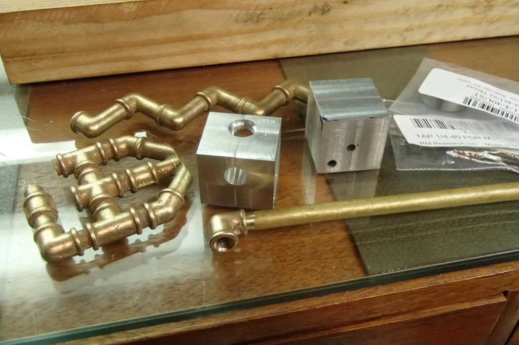
Ok, just cut the piece off and re-glue it along side of the pin. I cut it and it dropped and disappeared somewhere on the floor I just swept the day before. Luckily the new hole was far enough away that I should be able to do without the filler. I finished the counter bores and again with some tweaking I tried a tee and it was happy, happy, happy.
I didn't drill and tap the tee yet, because, hopefully, it is going to become the intake valve housing for the new 1/3 scale H Ford I'm currently building, which I'm going to rename the Lil' Henry, and I've decided to go ahead post the build.
Not sure at all if this engine will run, some of it is still on the drawing board, it will indeed make a nice shelf pet if things don't work out.
GUS
As a little teaser, you can see part of the Lil' Henry's base in the first pic of this post.


 , I don't feel I'm up to it, just yet anyway.


