This is my projects so far.

Home Model Engine Machinist Forum

Help Support Home Model Engine Machinist Forum:

This site may earn a commission from merchant affiliate links, including eBay, Amazon, and others.

hobby

Project of the Month Winner!!!
Project of the Month Winner
Joined
Dec 5, 2009
Messages
510
Reaction score
47
Hi,
This is a nice forum to share our projects.
I've been into homeshop machining as a hobby, among many other hobbies, for around 7 years now.
I started out making all kinds of tooling and small repair parts, then about 2 years ago I got interested in designing and building mechanical projects.
So I looked on the inernet to see a animation of how a steam engine works, and after finding the concept, I got on my cad program and designed my own from scratch.
it is a double acting classic steam engine, it was a lot of learning experiance to get it wotking did a lot of reworking and rebuilding until I finally got it to work,
but once I did then the rest of the engines after became easier to get running on the first or second try.

I have a 7 x 10 mini lathe, and a Micro-mill drill, (harbor freight) and a 4x6 bandsaw and a small benchtop metal bandsaw. Benchtop grinder, and drill press. Among other tooling and such.


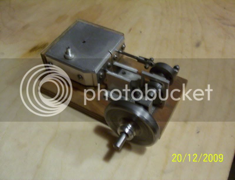
Here is the first one.

firstengine.jpg


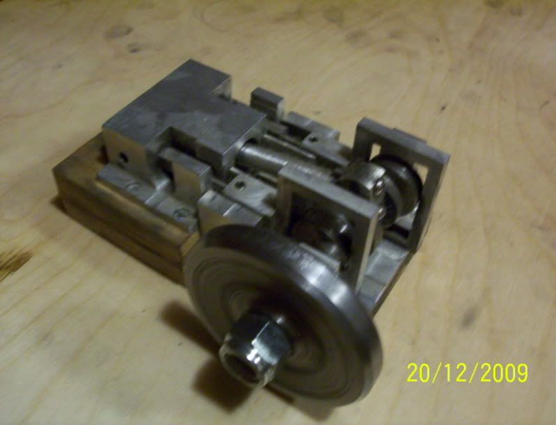
second one, this runs forward and reverse, depending on wich side air is intaked.

secondengine.jpg


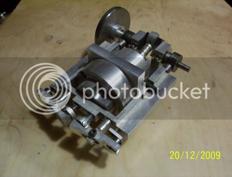
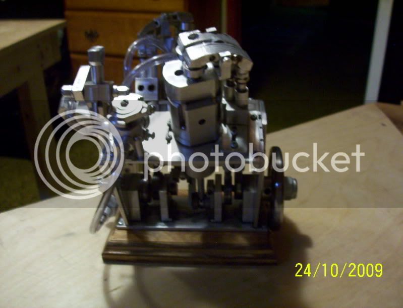
third one, this one is not the steam engine concept, but works with valves and rocker arms, pushrods, still a steam (compressed air engine) just a inter comb. engine concept.
This is a poor design for the intake valve, due to high pressure intake, causes the intake valve to remain pushed down into the cykinder, that's why a heavy valve spring on the one side and a lite spring on the exhaust.
Works good just can't over work the air intake.

thirdengine.jpg


Fourth engine, learned from my mistake with the intake valve and designed a intake valve system that does not enter into the cylinder, but the air is routed around it when depressed in it's own compartment, this is the best running yet, it is self starting when air is applied, even has a throttle.
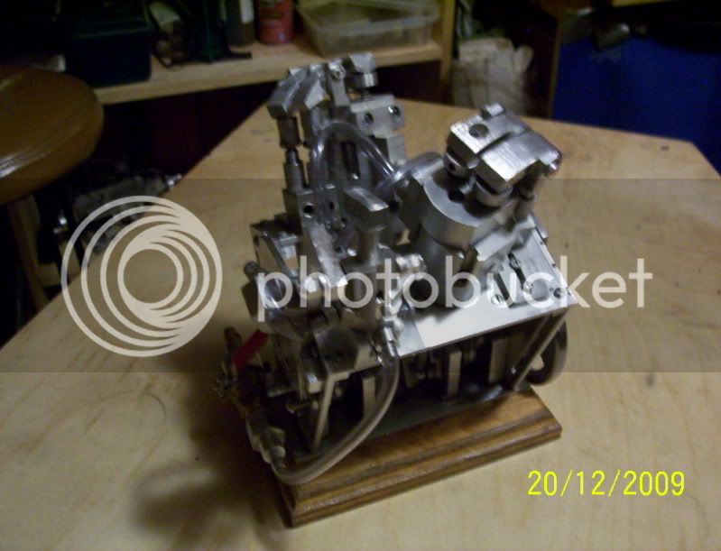
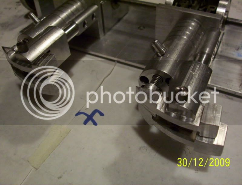
fourthenginefront.jpg


another view.
fourthengineside.jpg


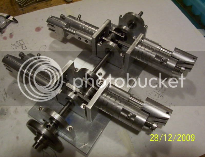
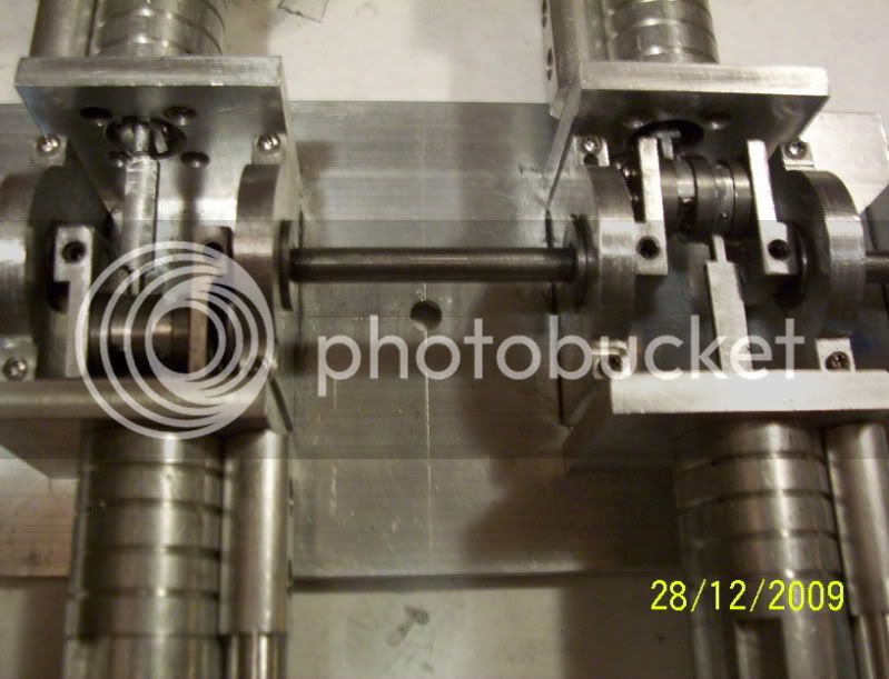
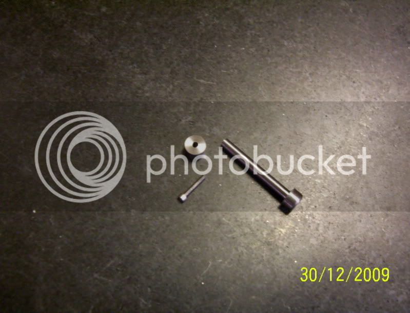
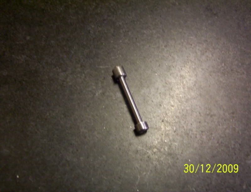
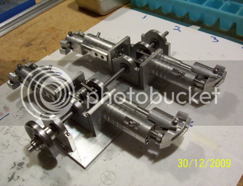
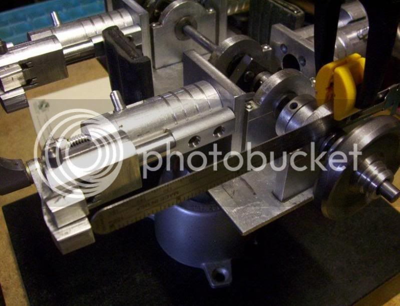
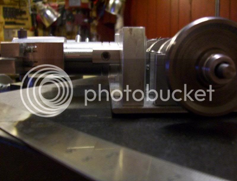
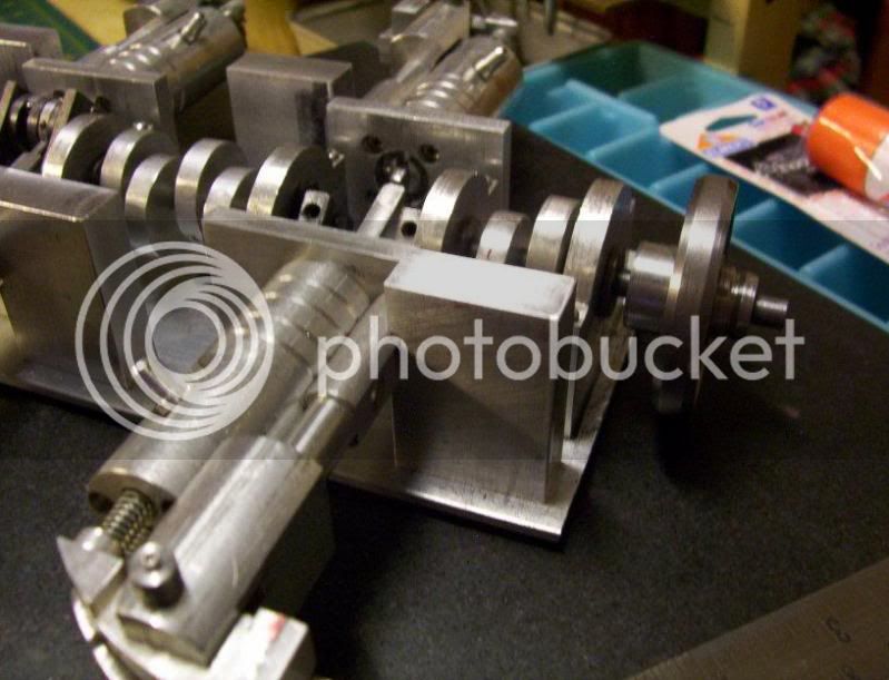
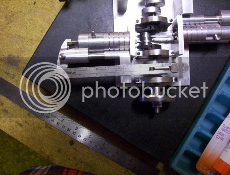
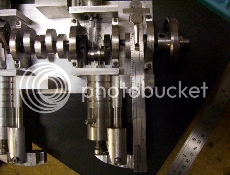
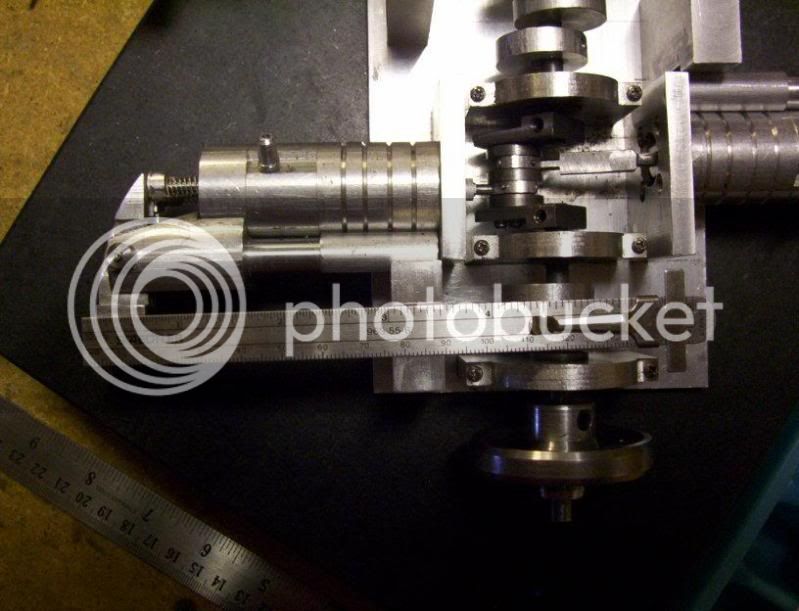
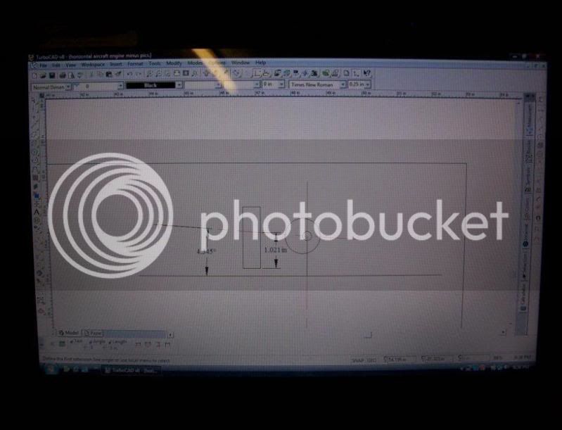
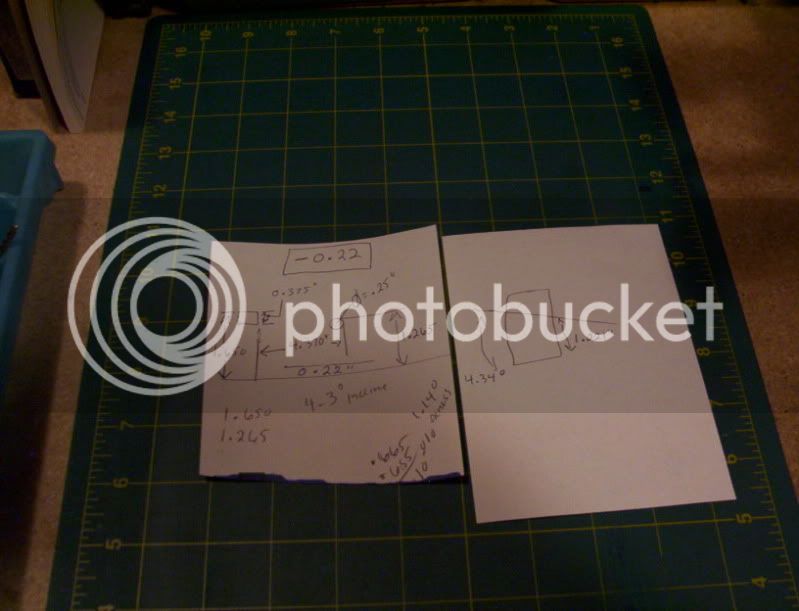
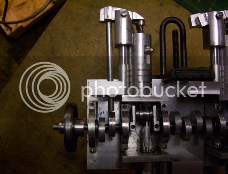
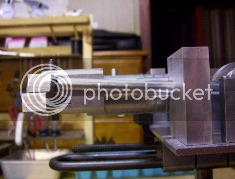
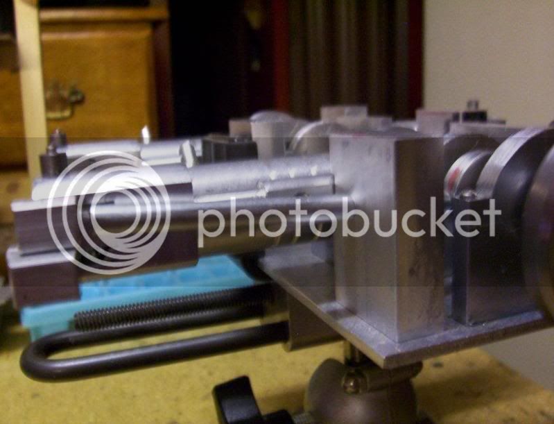
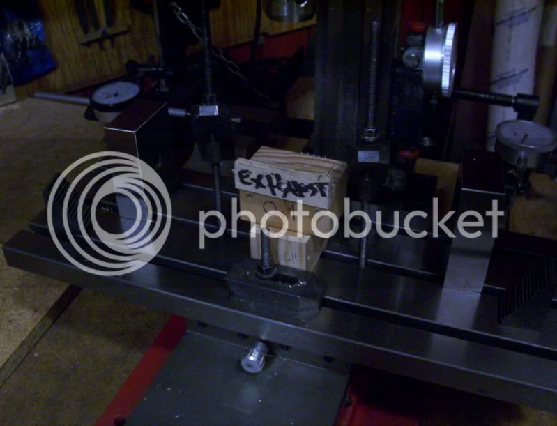
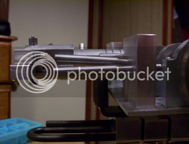
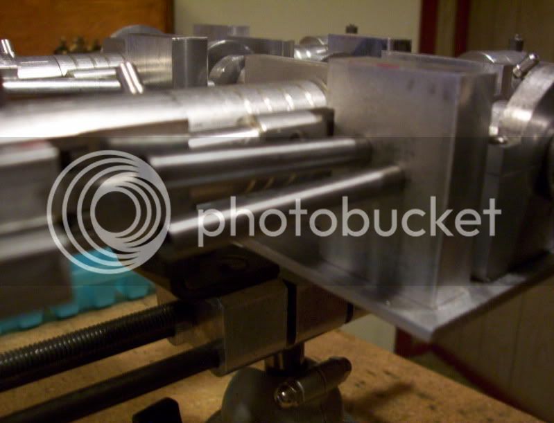
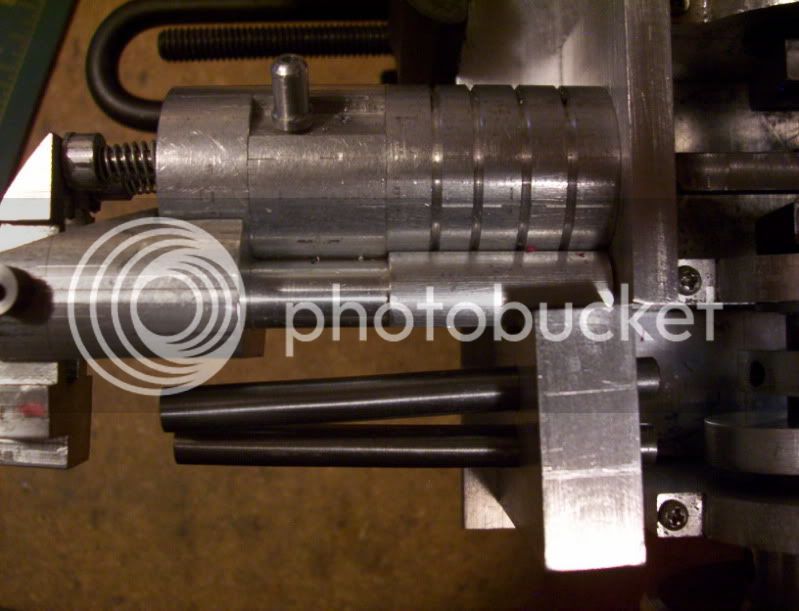
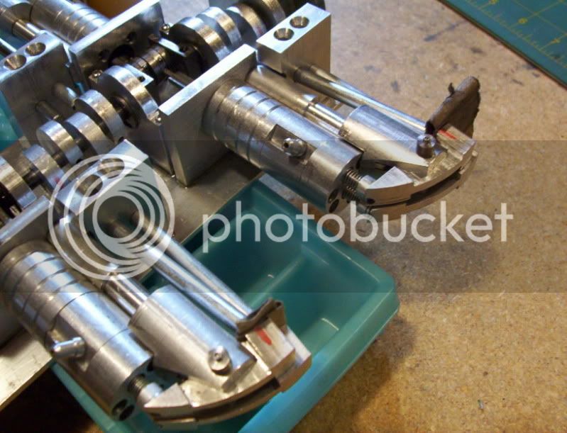
And this one I am currently working on on weekends,
it is a horizontal 4 cyl. engine, an aircrafty type concept.
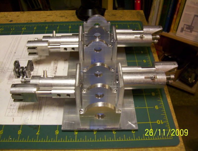
fifthengineinthemaking.jpg


Thankyou.
For letting me share.
and
Merry Christmas
God Bless...
 
I'll second the 'wows'...thanks for sharing that stuff! I'm looking forward to more updates on that Flat Four.
 
Welcome to the forum hobby.
Yeah...I'll be interested in seeing more. Absolutely.
 
Welcome to HMEM hobby.

Interesting builds! :bow:

Rick
 
Very impressive, especially considering they are designed from scratch.

Jim
 
I like the mechanical looking aspect of your engines. Things like the size of the rockers and links give it almost a robotical look. They're very nice in that they're a departure from the standard looking engine. Keep up the good work.
gbritnell
 
Hobby,

Welcome to our forum.
icon_welcome.gif


Impressive designs. :bow:

Best Regards
Bob
 
Thankyou,
Everyone for the nice warm welcome,
and the compliments.

When I get my next engine done, I'll be sure to post it.

Have a great day... :)
 
+1 on gbritnell's comments. I also like the look - there are obvious signs of the "style" or family lineage amongst the engines. Great work! Welcome to the cage!!

Garry
 
Hi Hobby - I hope that you will become a regular visitor to HMEM. Seasons Greetings - Billmc
 
Here is an update to my current engine, design and build.

Crankshaft built up and installed.
And piston con. rods connected.
Temporary flywheel.

100_1344.jpg


100_1343-2.jpg


Have a great day.. :)
 
here was a fun project.

Looked for a picture of those kwik clamps, on the innernet. then tried to fabricate my own the real fun part was designing the fixtures needed to hold the parts for machining.

100_1357.jpg


another update on the horizontal.

Using my build thread to practice posting updates on my projects, to learn how to make my postings somewhat interesting. Before I use the "work in progress" forum.

last few days, I made a wooden fixture and double stick taped it (after acurate lining up) to my rotary table, than clamped down 4 (intake) rocker blanks, and milled the profile.

Then made a new wooden fixture for the exhaust rocker blanks, (there larger in lenghth) and did the same.

100_1347.jpg


100_1349.jpg


100_1350.jpg


then milled out the recesses on both sides.

100_1351.jpg


100_1353.jpg


then machined the shafts for the rockers to rock on.

100_1358.jpg


100_1359.jpg


and the assembly of the rockers (preliminary), for test fits.
100_1360.jpg


100_1361.jpg


Nice work Hobby, can't wait to see that one run!


IronHorse
 
Some more updates on my latest project.

Now it's time to figure the angles needed to drill through the block, that holds the push rod tubes.

100_1364.jpg


100_1365.jpg


100_1366.jpg


100_1367.jpg


100_1368.jpg


100_1369.jpg


Now to record all the dimensions measured.

100-1363.jpg


100_1362.jpg


It turns out to be a compound angle, 1.14 deg. on the horizontal, and 4.34 deg. on the verticle.

Now to make a drilling jig that is tilted at a compund angle.

the first angle block screwed to a wooden jig, attached to my rotary table.

100_1370.jpg


Now I'll set the RT, to 0 and mill the bottom, and one side to be the datums to work off of. first.

100_1371.jpg


100_1372.jpg


Now I'll turn the RT. to 4.34 deg. to mill the top section, at the angle.

100_13705.jpg


100_1374.jpg


The first angled block done.

100_1373.jpg


Now the second one is milled at the 1.14 deg.

100_1375.jpg


Both blocks milled and ready to be assembled together.

100_1377.jpg


Both blocks are now glued together at there proper orientations. To become the final drilling jig.

100_1378.jpg


100_1379.jpg


Time to set up for the drilling of the actual workpiece.

100_1380.jpg


100_1379.jpg


100_1381.jpg


Now drilling the workpiece.

100_1382.jpg


100_1383.jpg


Now a test fit to see how the angles look.

Top view.

100_1384.jpg


and side view.

100_1385.jpg


Ok lets cut a piece of 1/4" rod which will be the dia. of the push rod tube, and see how well it lines up with the center of the cam (eccentric), and the target point on the rocker arm.

100_1386.jpg


Lines up exactly as planned.

100_1387.jpg


100_1388.jpg


That is just the intake tube.

Now I need to recalculate the angles and make another angled drilling jig, for the exhaust tubes as well.

All in all by taking my time this cam out very acurately.


Thanks for taking a look.

Have a great day... :)


some more updates,

I took 1/4 steel rod, and drilled and reamed an inside diameter to 0.1865",
this will be the pushrod tubes.

Then I took all neccesary measurements, and built up another compound angle drilling fixture.

100_1389.jpg


This happens to be 0.9 deg. down on vertical axis, and 2.8 deg. to the right on the horizontal axis.

Here is the results of todays work on drilling the first block, this now shows both the intake push rod tube on top, and the exhaust push rod tube at the bottom.

They both (push rod tubes), start out at the quadrant on there respective cams (ecentrics).

But as they go through the block they begin to overlap, while the intake (top) juts to the left and upwards,
and the exhaust juts out to the right and downwards, looking out from the crankshaft.

here are the picrures showing these compound angled tube directions.

FRONT VIEW.

100_1391.jpg


LEFT FRONT VIEW.

100_1392.jpg


and the TOP VIEW.

100_1390.jpg


Next is to drill the the other 3 blocks, drill and ream the pushrod tubes, drill for set screws in each block to hold the tubes, then begin working on the push rods, themselves.

when I get one set of pushrods done, I will have enough components, in the build to test run one cylinder, to see how it works..

That's all for now...

Thanks...
 
another update:

Hi everyone,

On my current project I am working on a 4 cyl. horizontal engine.

Over the weekend, I was able to get enough parts machined to put together one cylinder for test running.

The first picture shows I put sandpaper between the rocker arms and the push rod tubes to force both intake and exhaust valve open to lessen compression drag.

100_1515.jpg


This one cylinder still working against 3 cylinders, that still have some air compression friction, due to the fact that the exhaust port and intake posrt sre snall orifices leading into there cylinders.


So here is a test run of 1 cylinder.


Thankyou...


Latest posts

Back
Top