This is my projects so far.

Home Model Engine Machinist Forum

Help Support Home Model Engine Machinist Forum:

This site may earn a commission from merchant affiliate links, including eBay, Amazon, and others.
Nice looking engine.

Great layout work.

I bet it will sound really good when all cylinders are powered.

What do you have in mind for the "Bling"?

SAM
 
Zeep,
Thankyou,

its progress, slow but sure, I still have a ways to go before I can
truly say it's done, but now comes the tweaking, and things..

Sam
Thanks,

I think the only bling I'll be able to give it is first finish it, :big:
But I was thinking about making a wooden form on the bottom, to make it look like an oil pan, to give it some shape, and fabricate a proportional size propeller, to make it look like it has some purpose... ;D

Then add extra's here and there, if I don't get overly anxious to get it done, so I can begin another project... :)
------------------------------

Have a great day...

 
This is next to the last update,

This shows the engine with Temporary tubing going to the intakes on all cylinders,

This setup was used to test run the engine on all 4 cylinders.

I don't want to show a video of it right here, because I want to wait until I get all the bells and whistles done on it, then I'll post it in a seperate thread, with a video of it running.

Here it is in raw form, working mechanical stage, BEFORE the finish work. Temporary tubing, at this point..

100_1518.jpg


Next time I post about this build, it will have all fabricated and machined intake manifold tubings, and probably a propeller.

Thanks for looking...
 
Hobby, that is one 'cool' looking engine. There's something about the way you build all your pieces. Like I said earlier, they have a truly mechanical look.
gbritnell
 
George,
Thankyou for the nice complement.

Have a great day.. :)
 
Hi everyone,

I was going to wait until this was all done, before I post on this,
but I decided to post some more updates on my engine,
so you know that there is progress being done on it.

The first picture is the jig I made for my rotary table to cut out the arches for the framework,
at the top of the engine.

100_1521.jpg


And here is that framework.

100_1523.jpg


Then today I began fabricating the, air intake manifolds for each cylinder,
that's the small angle cut cylinders on top of each piston cylinder.

100_1525.jpg


I made each manifold from 5/8" round stock, and put a 1/8" x .120" dia. nub on one end,
and then using a 6-32 die, threaded it.

Also above that for 3/8" I turned the stock to 0.375" dia. and then using a cutoff tool, made cuts in the 5/8" dia. top part, to look like some kind of cooling fins, just for asthetics, then also a 5/64" thru hole is drilled thru, for air inlet.

After that I made a fixture, to hold each one at the proper angle, to use a slitting saw, to cut them to proper angle and length. Then drilled and reamed a 1/4" dia. hole for fitting the air intake tube, and drilled and tapped 2 holes per each one, to attach the flange of the intake tubing, to follow.

So this picture is where its at to date...

100_1526.jpg


Next is to draw up and fabricate, the air intake system to tie it all together.

Thankyou...


Jtrain,
Thankyou for the compliment.

Also Ironhorse,

Thankyou for your kind compliment.
sorry for being so late with an acknowledgement to your post, I was just starting out new with this forum, and forgot to even check up on any updates in this thread, until I started posting updates again, and as I was going over this entire thread tonight, I seen your compliments, and thought I need to acknowledge back.

Also anyone I may have missed, I will see if there is anymore I missed achknowledging back.

Thankyou Gmac.

Thankyou BillMC.

For the nice comments.

Have a great day.. :)
 

Awesome job!

I love the mechanicalness of it all.
 
Truly a one of a kind. Thm: Very inventive.

Matt
 
Thankyou,

KEVIN and MATT and CARL,

i appreciate ya's looking in, and the ecouraging compliments.

Have a great week... :)
 
Hi,
Some more updates, not very exciting but just to let you know where I'm at in this build.

The intake ports I made before, needed to be made over, because I made a quick an inacurate fixture using round bar, with flats machined on it that could not be clamped to securely in my vice, as well as a inacurate gauge made out of a credit card to transfer the angle, which meant uneven cuts.Bad setup all together.

So I took the time to make a good fixture out of square flat stock, that could be positioned and clamped securely in my vice.

100_1542.jpg


As well as using my sliding T Bevel to acurately locate and transfer the angle to my workpieces.. Each intake part was guaged with this bevel square,

100_1535.jpg


and transfered to my milling fixture.

100_1536.jpg


Then was cut to desired length and angle,

100_1537.jpg


enlarged the intake port with a 1/4" drill, to depth of 1/8"

100_1538.jpg


then transversed the table 1/4" to drill and tap for a 2-56 screw hole.

100_1541.jpg


Then screwed it in place back on the engine.

100_1543.jpg


Here they are with the air intake tube brackets fastened to them.
These square brackets will be milled with some details so there not just square blocks.

100_1544.jpg


Thanks...


This is my work on the airintake manifold, I did today.

I started out with a piece of 1.5" dia. stock roughed out to 1.375" length.

I first machined a spigot to a 1" dia, by 3/8" long, to fit my 5C collet for my dividing head
where most of the work on it will take place.

100_1546.jpg


100_1547.jpg


Then turned it end for end to machine another spigot for the air intake stud.

100_1548.jpg


100_1549.jpg


Then began drilling and chamfer profiling, and tapping for 1/4-20 thread.

100_1550.jpg


100_1551.jpg


100_1554.jpg


100_1555.jpg


here it is befor the milling operation.

100_1556.jpg


Now put it in my dividing head and begin the milling operations.

100_1557.jpg


I take a look at my drawing, I did on my new drafting board at the dimensions I need to machine too,

100_1559.jpg


And now start the profile millings,

100_1560.jpg


100_1561.jpg


100_1562.jpg


100_1563.jpg


100_1564.jpg


Now drill and tap for 1/4-20 threads

100_1565.jpg


100_1566.jpg


turn it 45* more for the front tapping,

100_1567.jpg


100_1568.jpg


Here it is at this point, I need to make tube fittings for these threaded holes, next.

100_1569.jpg


100_1570.jpg


Thanks again...


Hi,
Some more updates,
This is work on the Air Intake system.
I did this weekend.


The cylinder plumbing.

100_1571.jpg


100_1572.jpg


100_1573.jpg


One section attached to the bank of left cylinders.

100_1576.jpg


The Air Intake manifold.

100_1587.jpg


100_1581.jpg


100_1582.jpg


100_1583.jpg


100_1584.jpg


Is it just me or this thing starting to look like something out of science fiction movie?

I like it ;D
Keep up the good work, hobby.
 
Hi Hobby. Your build is progressing well. That's defiantly a unique design that can only come from a very creative imagination. Your builds display a menacing robotic theme with a futuristic style direction that's unlike anything I've seen before. I stared at the picture of it on the granite plate, and got freaked out a bit by the life like science fiction horror that emits from you project.

I meant the last sentence in a complimentary way. Its Art your creating, when it brings emotion to the surface of the admirer. Excellent work Hobby!

Thanks for posting your progress!

-MB
 
Hi,

You guys cracked me up, Rof}

Thanks for the compliments,

I never thought about it, until after you mentioned it, then when I went back and looked at the pics. That does look science fiction. I began to crack up laughing so hard, brought tears to my eyes, I was laughing so hard.

I had to post this one.


Untitled.jpg
 
.......You know it when you see it, the art in the mind of man transformed to metal! :bow: You have some serious concepts going on here Hobby............now will you have the next "Terminator IV" cyborg character done in time?? ;)
 
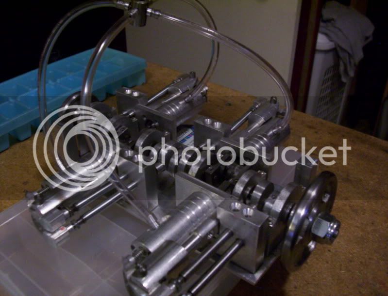
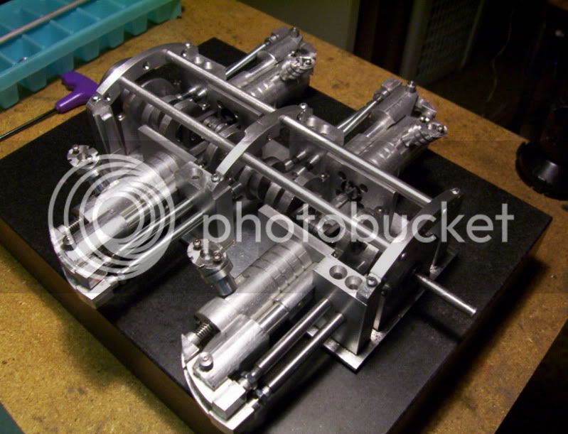
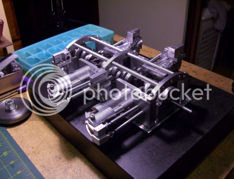
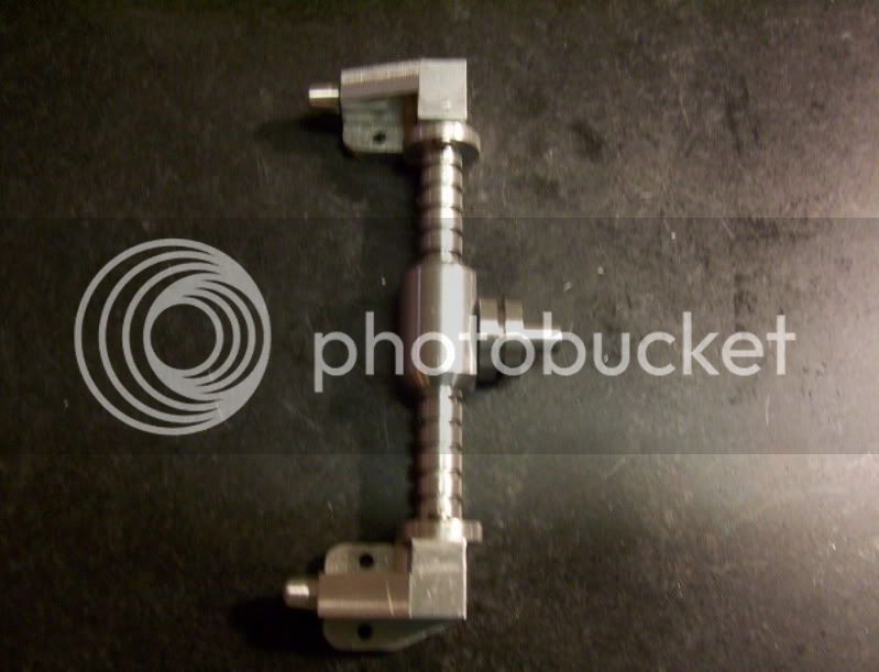
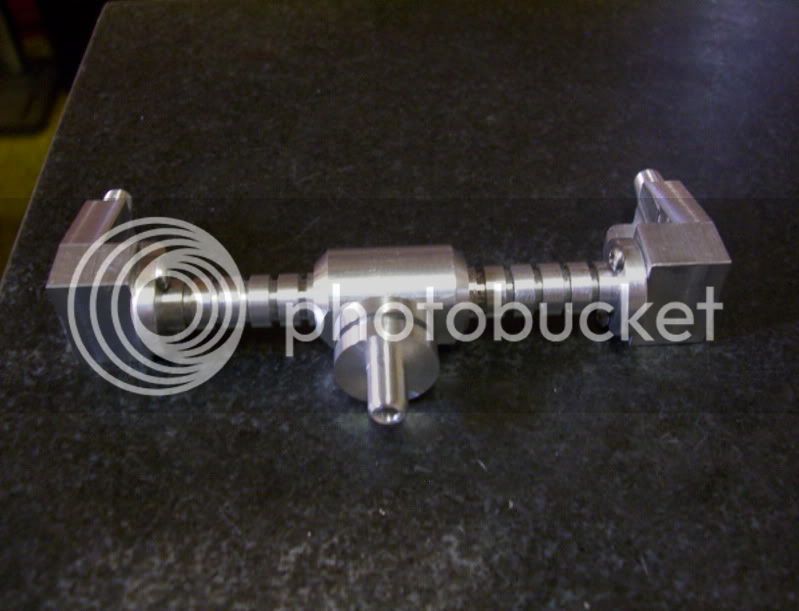
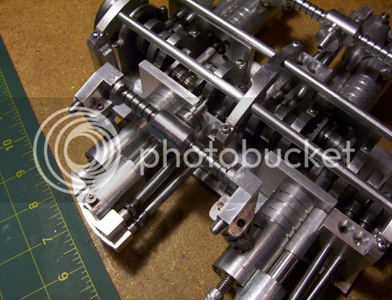
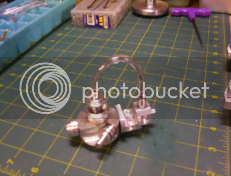
This was the original idea for the air intake system.
However the tubing is just too high of a loop, to work with my model engine.

100_1619.jpg


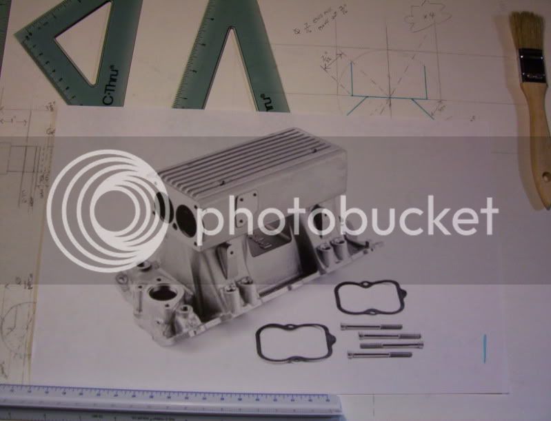
I want to replace the tube with a solid machined workpiece, so I did a innerenet search for images of air intake manifolds, and after searching througha dozen or so, I found the exact one I was looking for, to use as a model for fabricating my own.

Here is what I found on the innenrnet.

100_1606.jpg


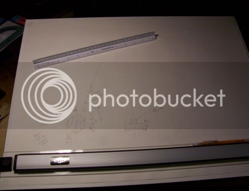
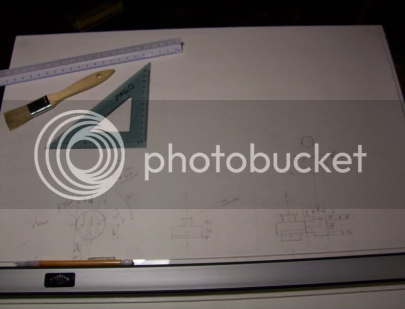
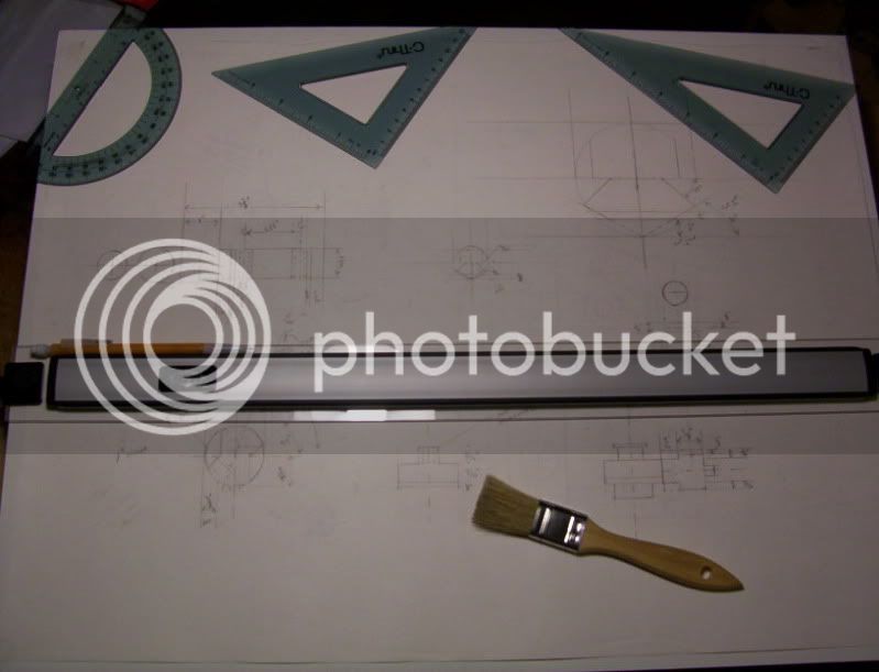
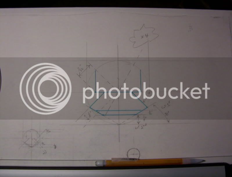
Now instead of CADing it, I get to use my new drafting board to draw this up with my own dimensions.

100_1590.jpg


100_1599.jpg


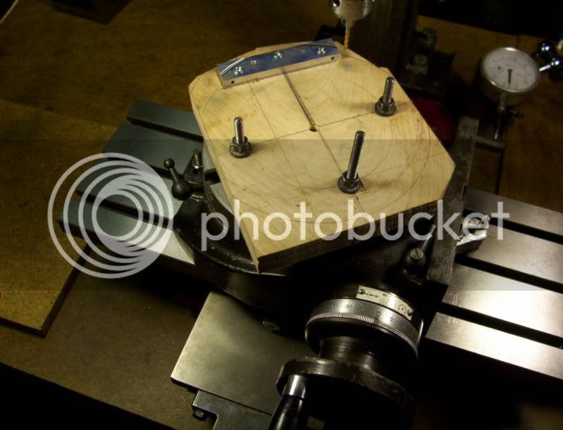
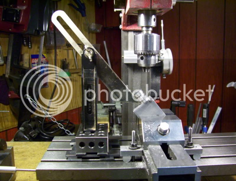
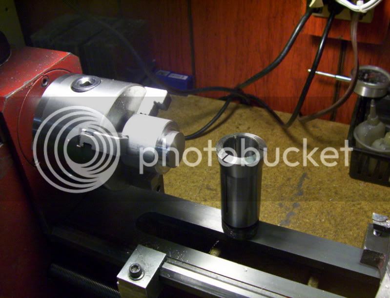
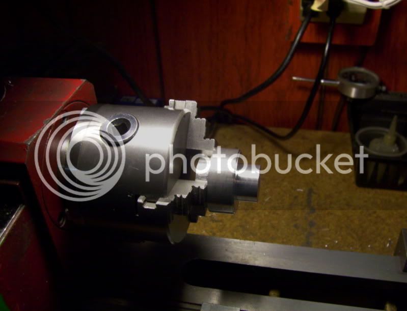
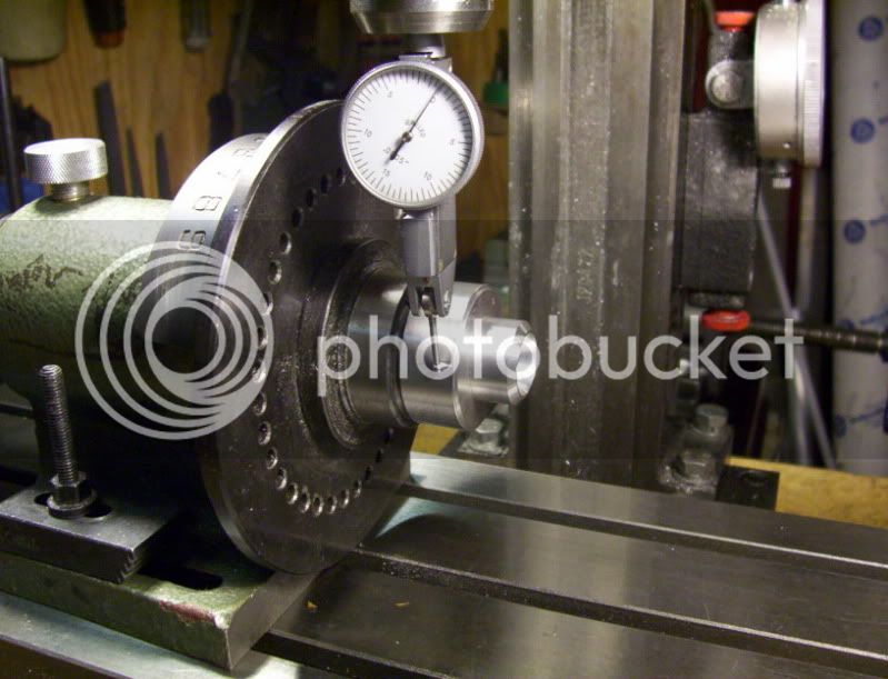
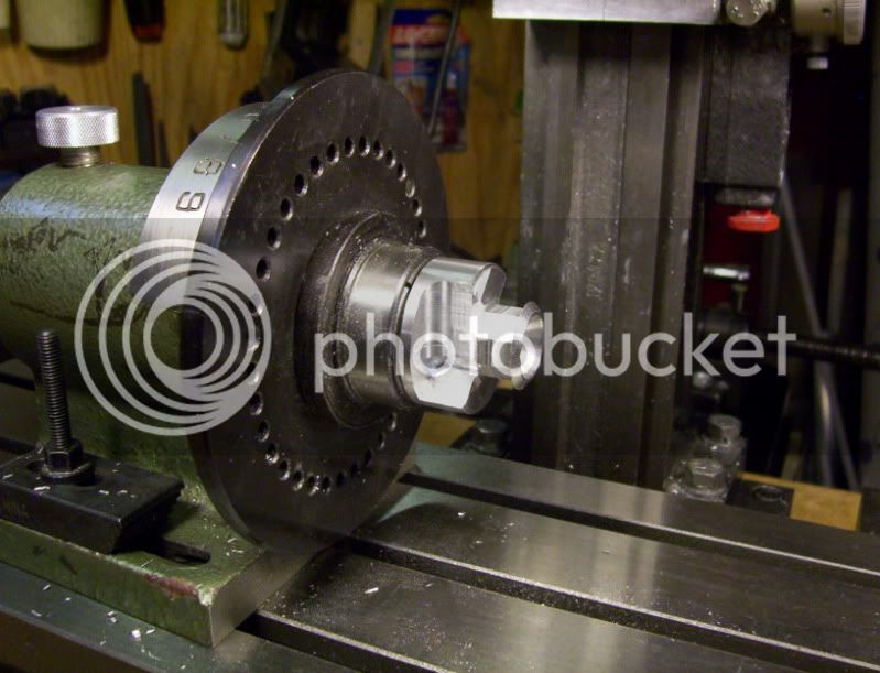
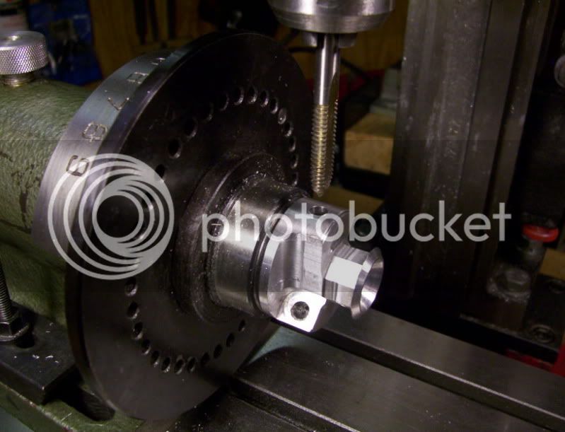
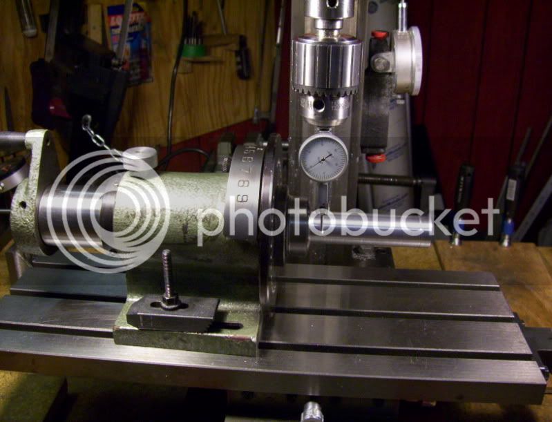
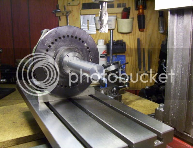
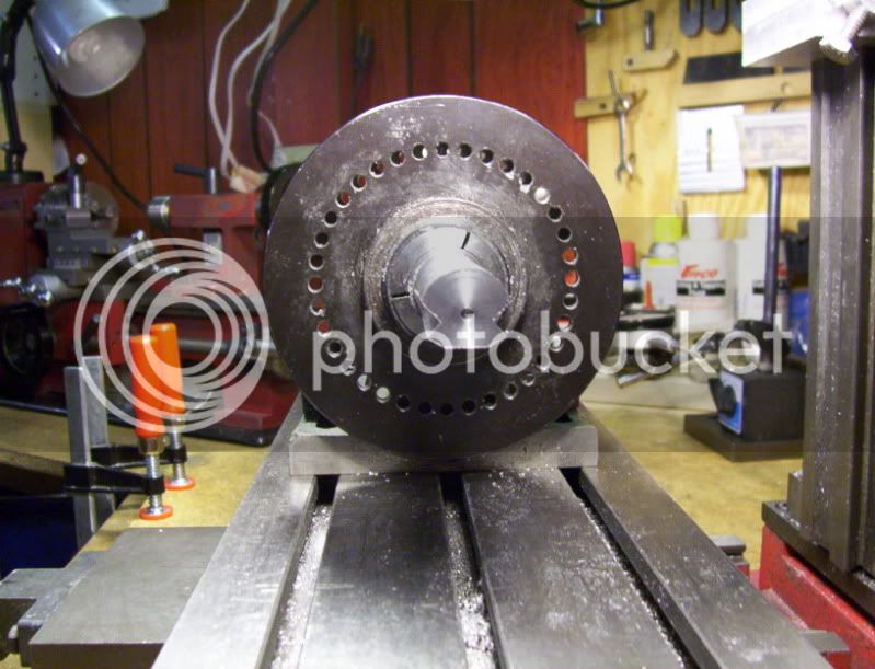
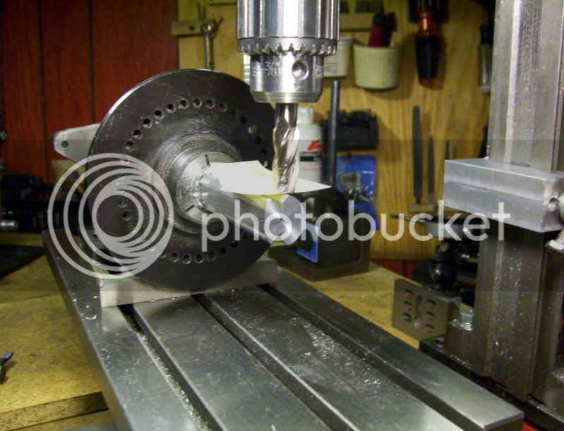
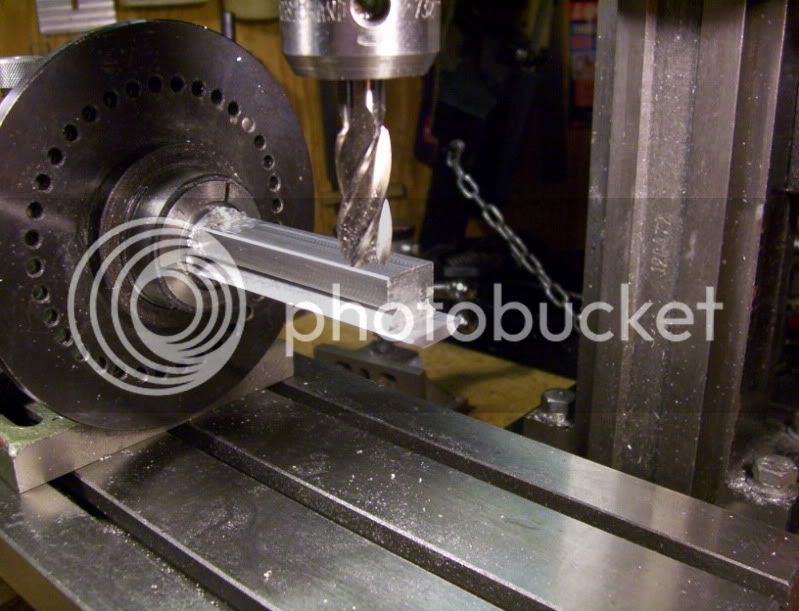
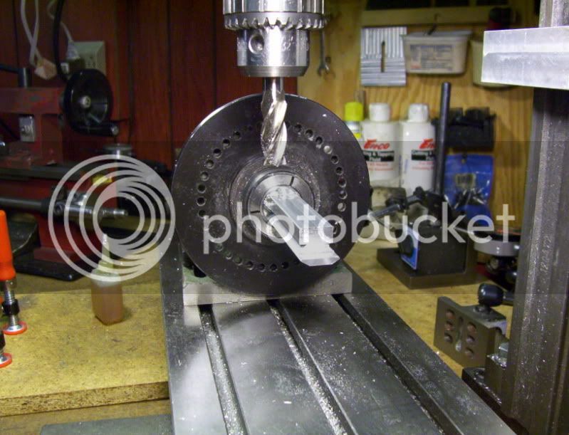
Since there is a few angles to mill at, I will use my 5C collet dividing head.
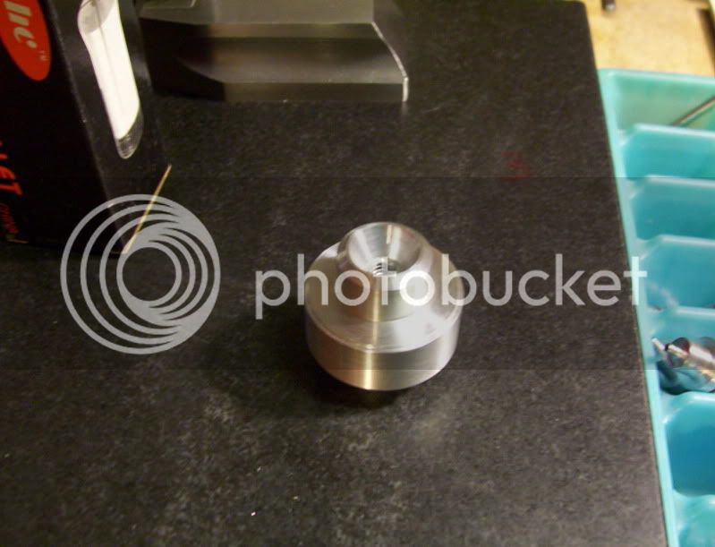
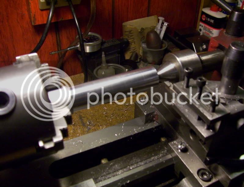
I want the whole workpiece to be made out of a 7/8" dia. round bar aluminum, so I used a 1" dia. bar, so I would have 1/8 clearancwe when I machine the profile on the back side towards the collet.

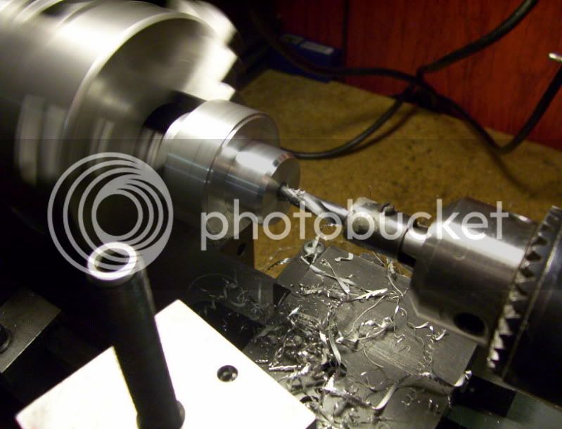
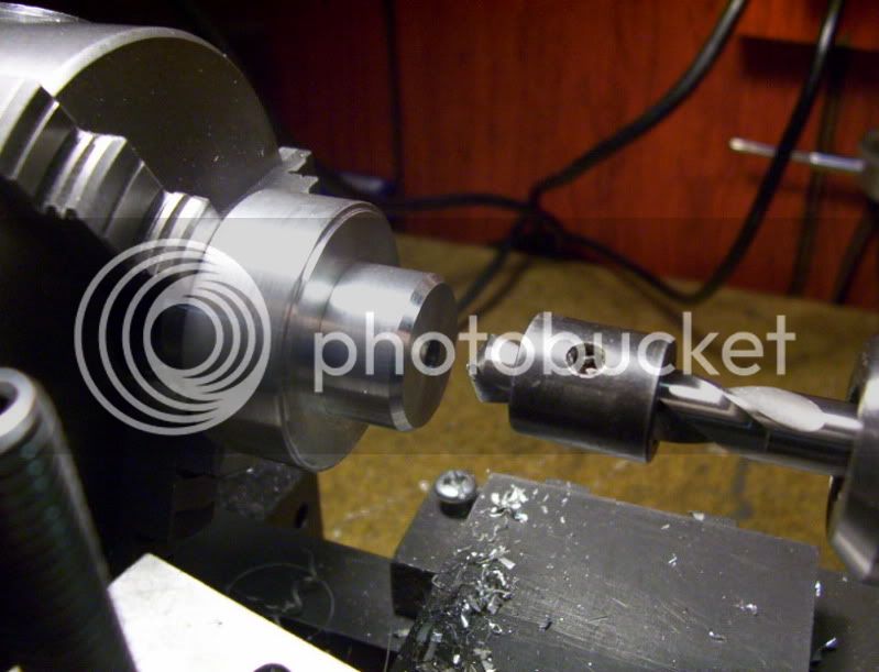
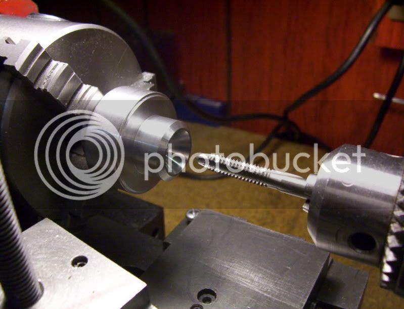
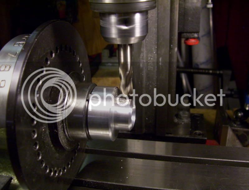
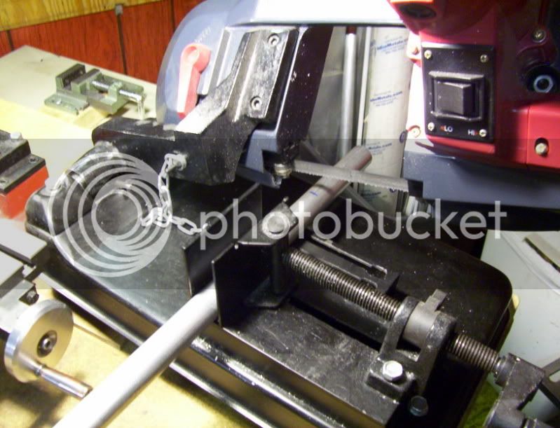
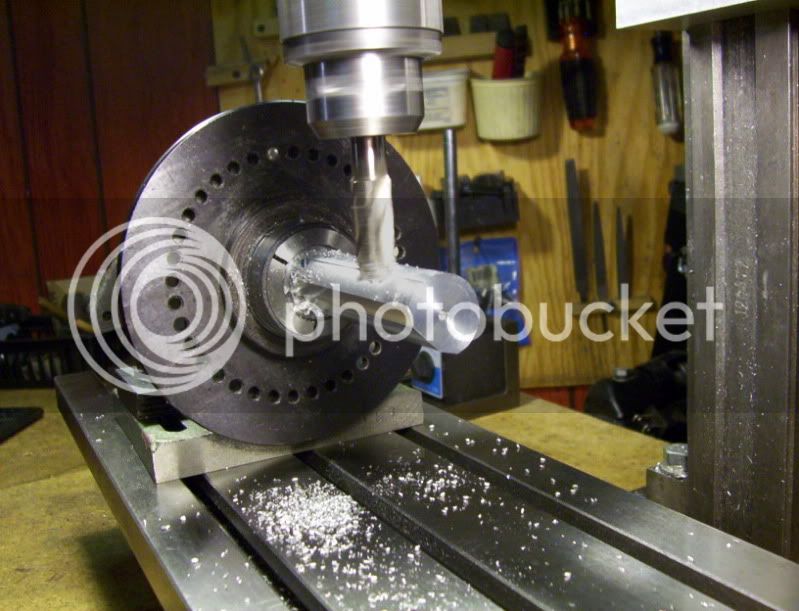
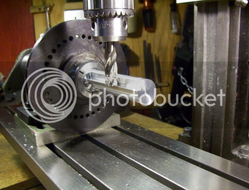
first up, cut a piece off of a 1" roundbar, then turn it to 7/8" dia. then set it up in the dividing head.

100_1588.jpg


100_1589.jpg


100_1592.jpg


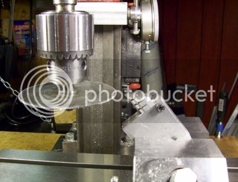
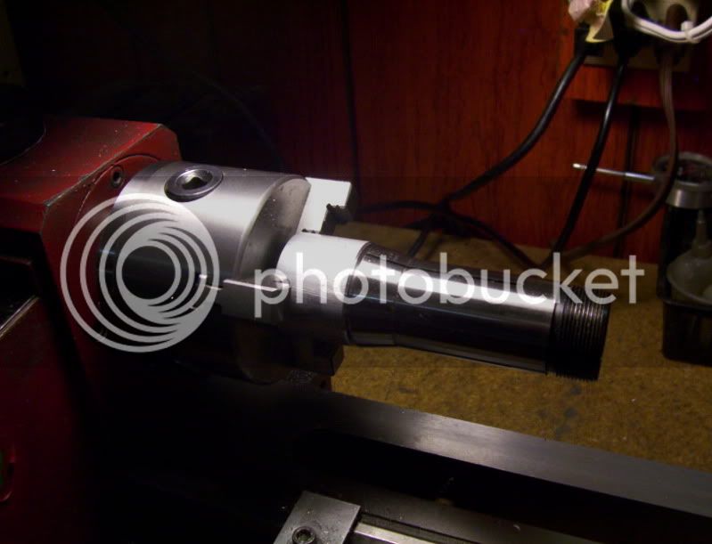
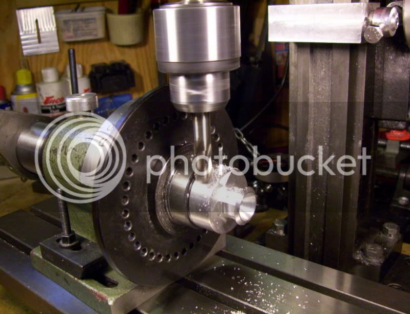
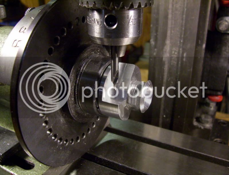
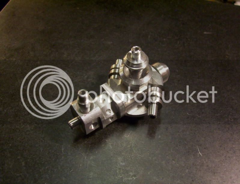
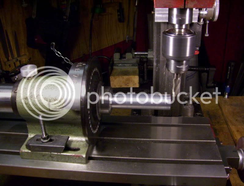
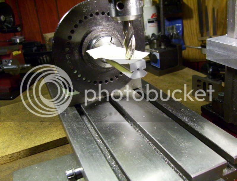
Now I have it set at 0* for the bottom side. I turn it 30* mill onw flat, then turn it 30* off of 0* the other direction to mill another flat, giving a "V" shape with an included angle of 60*.

Than I turn it back to 0*, to mill a third flat, and this will be the actual bottom surface, with 2 sides extending out at 30*

100_1593.jpg


100_1594.jpg


100_1595.jpg


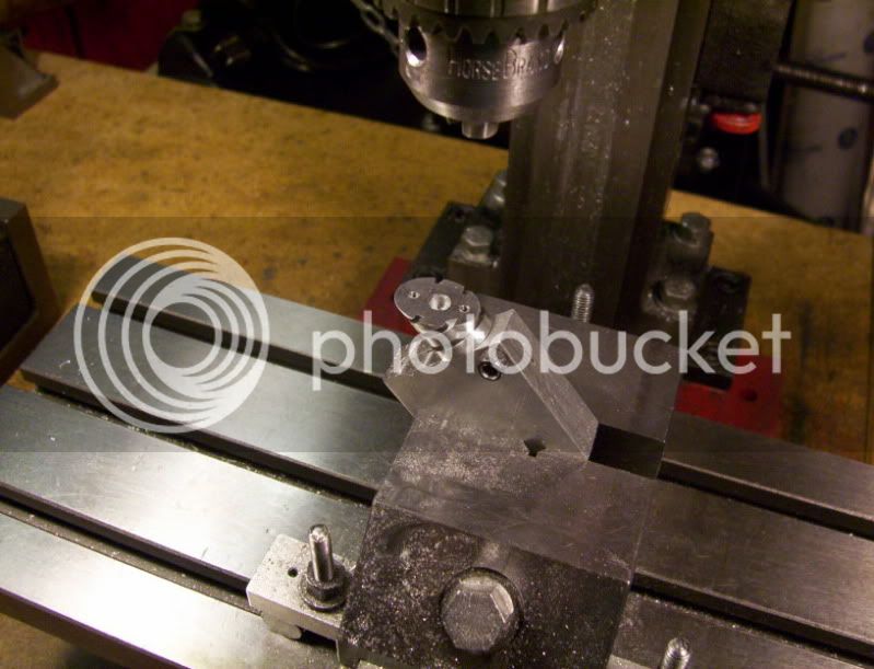
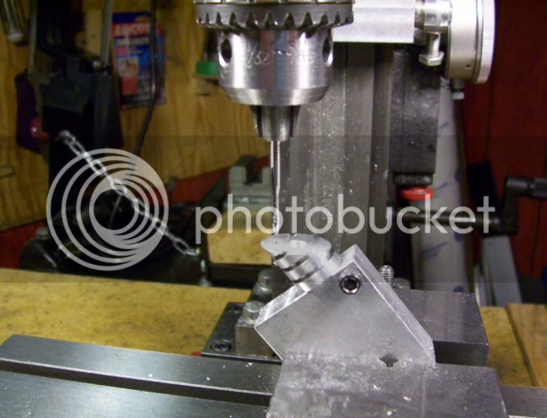
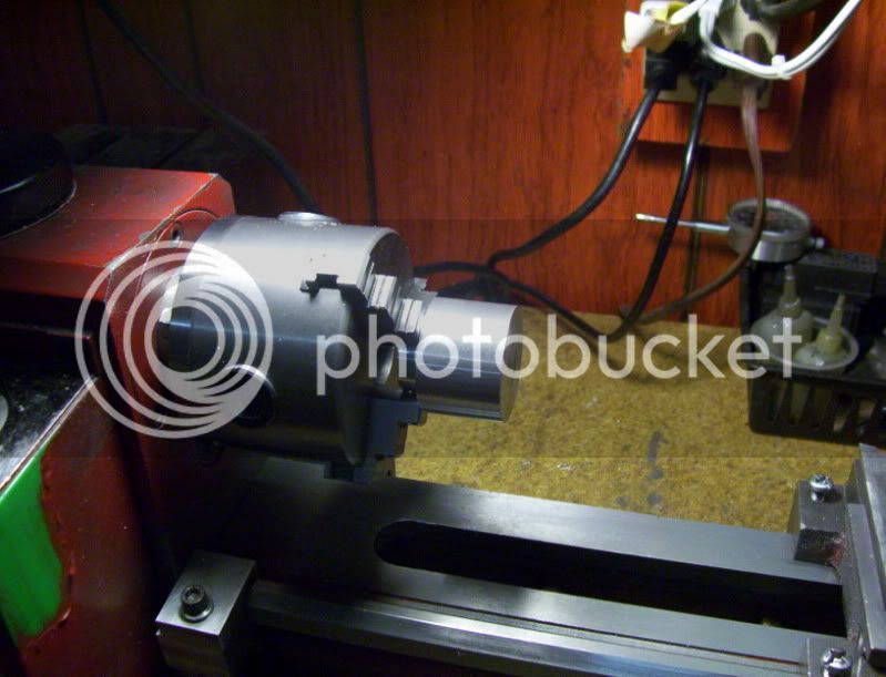
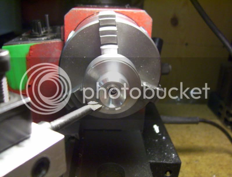
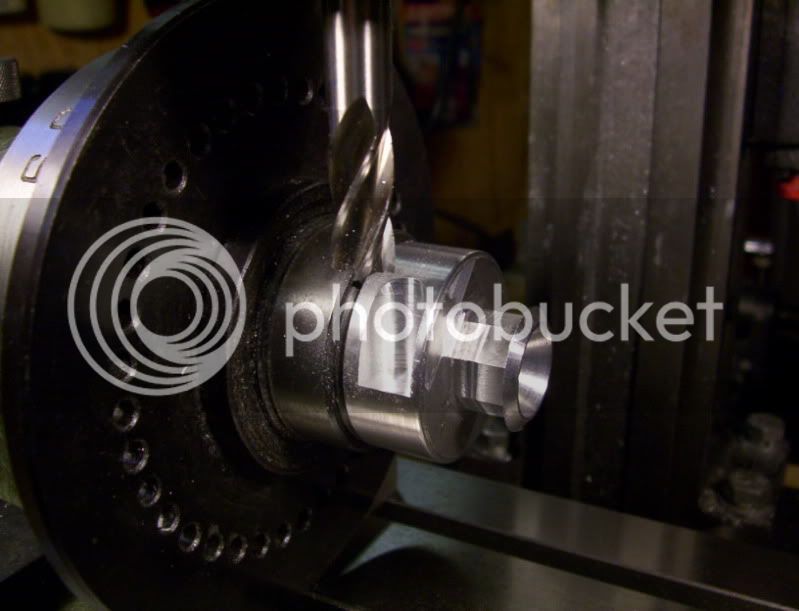
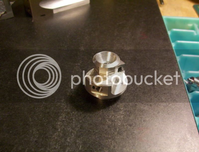
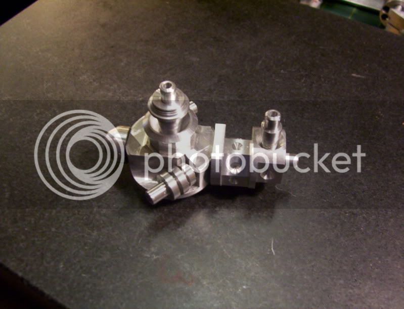
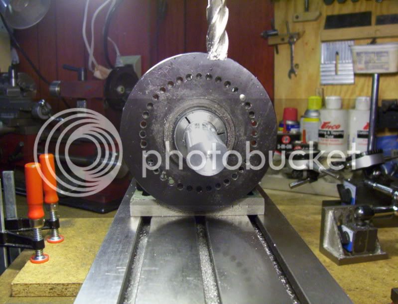
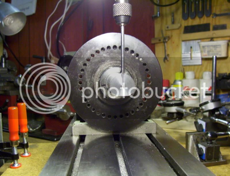
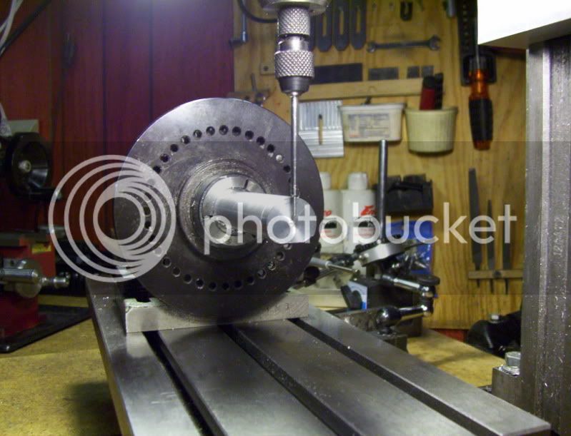
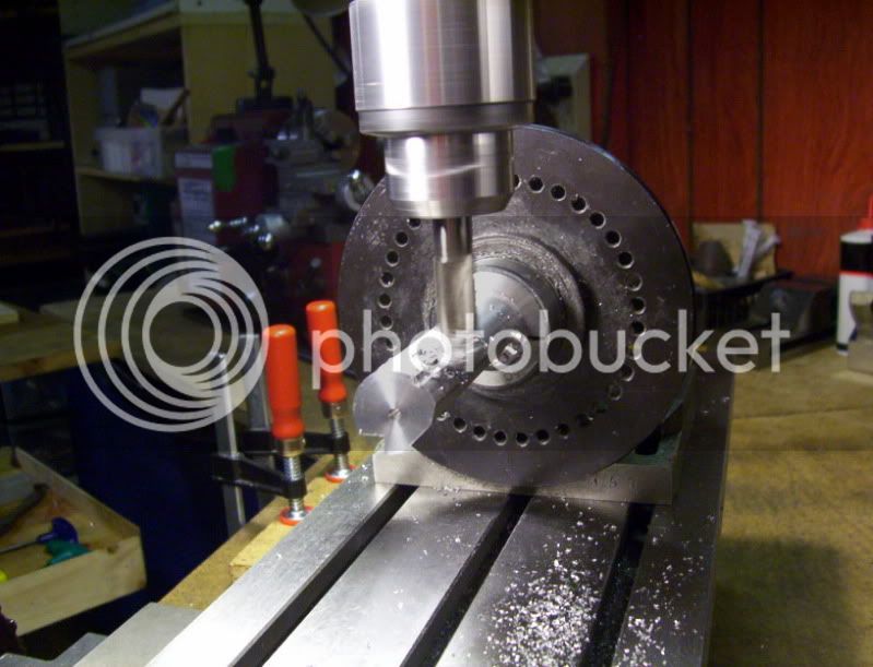
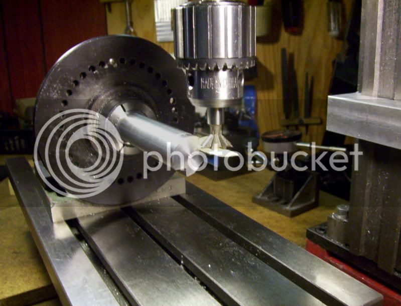
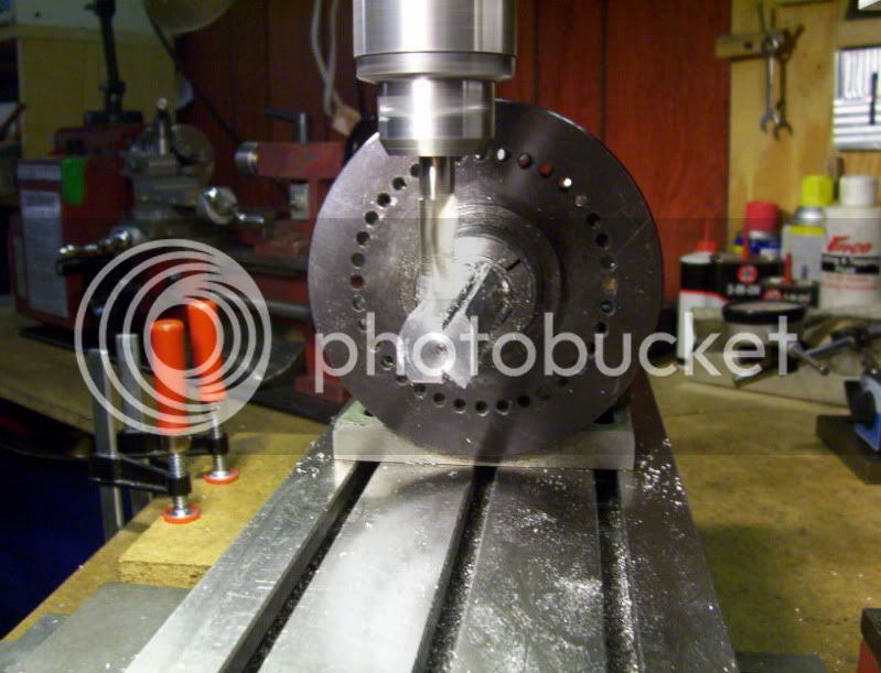
Now I turn it 180*, and this is now the top of the workpiece. From there I now turn it 45* to machine a shoulder, followed by a 45* dovetail cutter, to profile the middle of the workpiece. But first I need to establish the workpiece center. and locate the dimensions for machining.

100_1596.jpg


100_1599.jpg


100_1597.jpg


100_1598.jpg


100_1600.jpg


100_1601.jpg


100_1602.jpg


100_1603.jpg


100_1604.jpg


100_1609.jpg


100_1610.jpg


100_1611.jpg


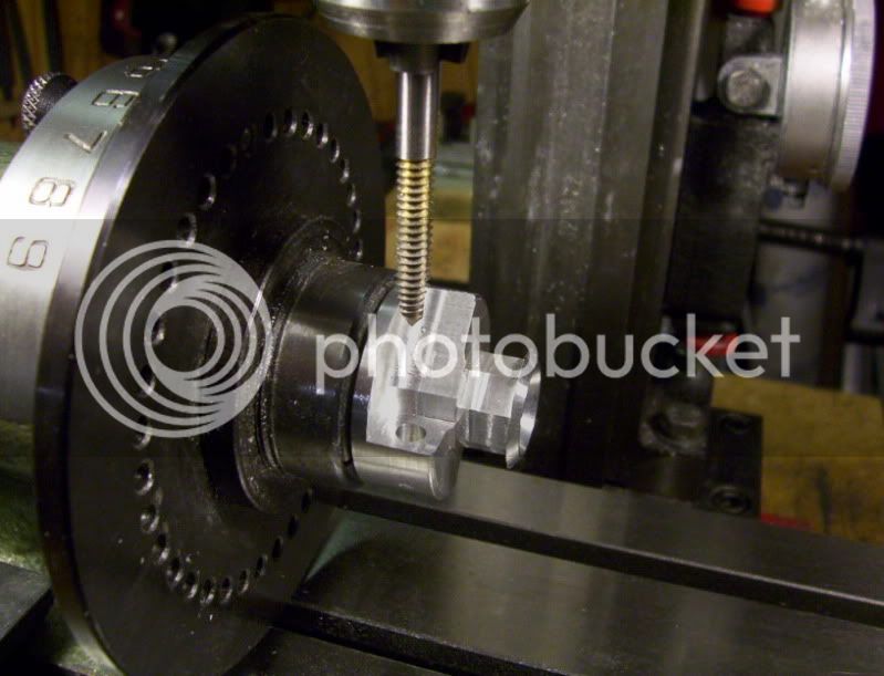
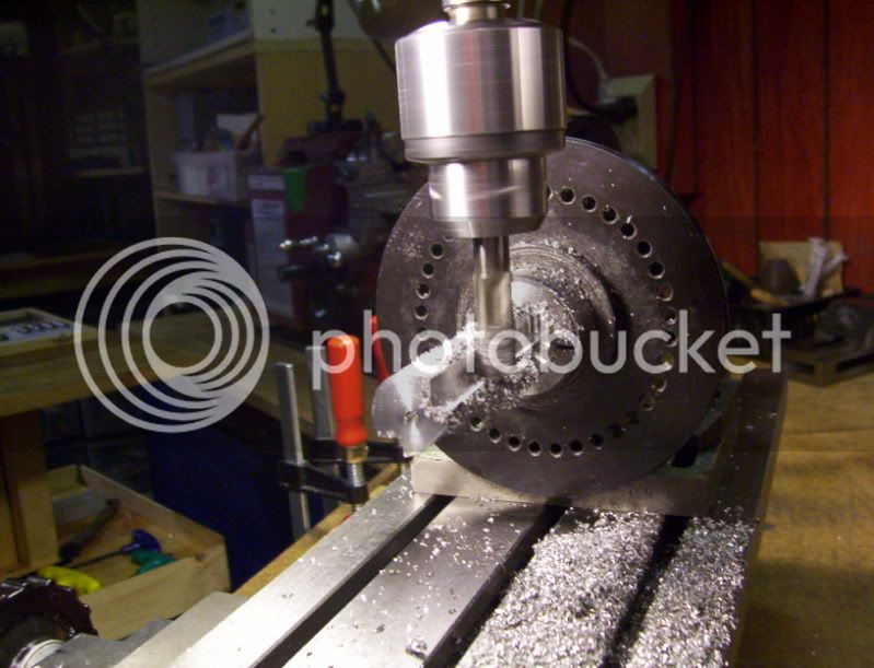
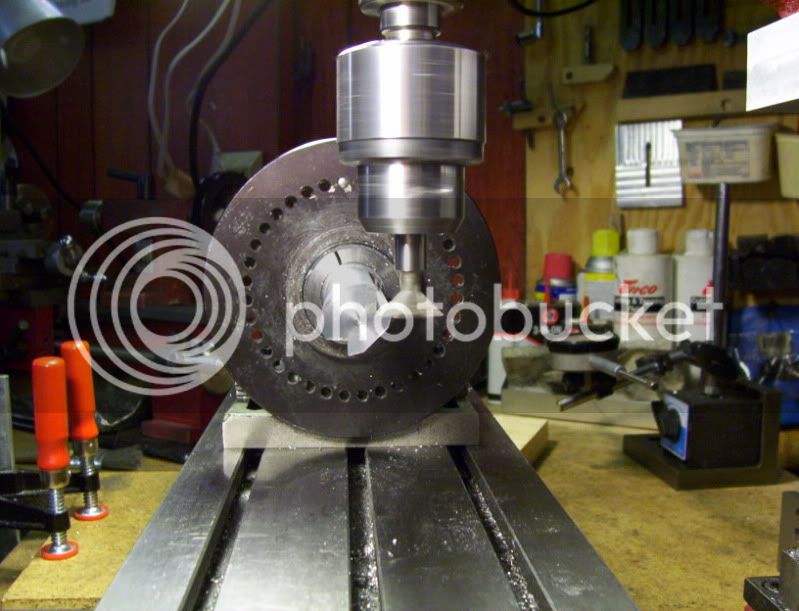
Now to mill the top portion the sides first then the very top.

100_1613.jpg


100_1614.jpg


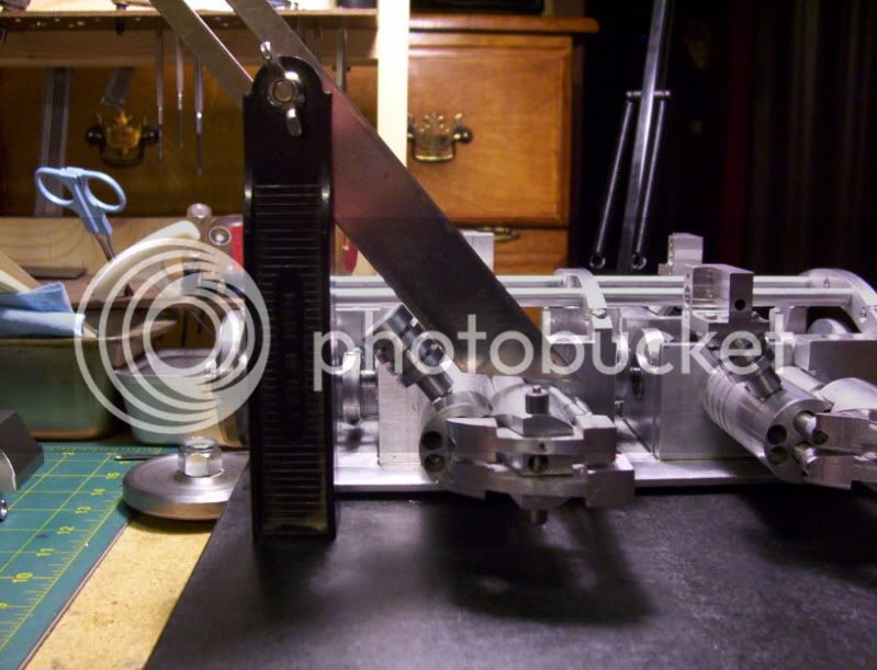
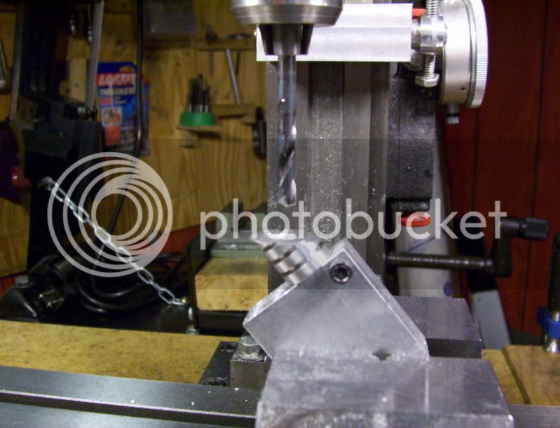
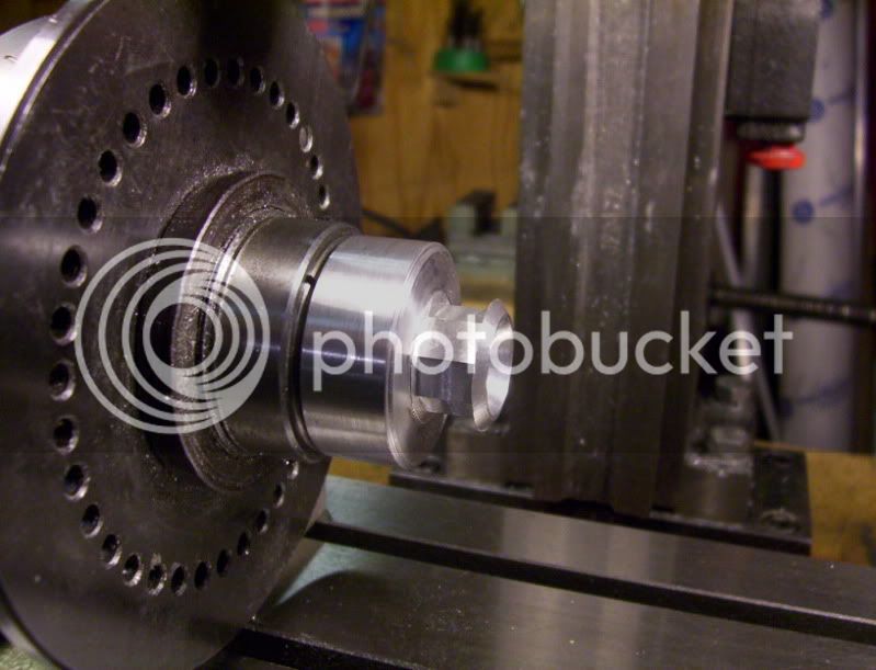
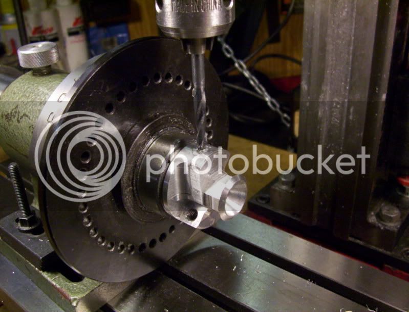
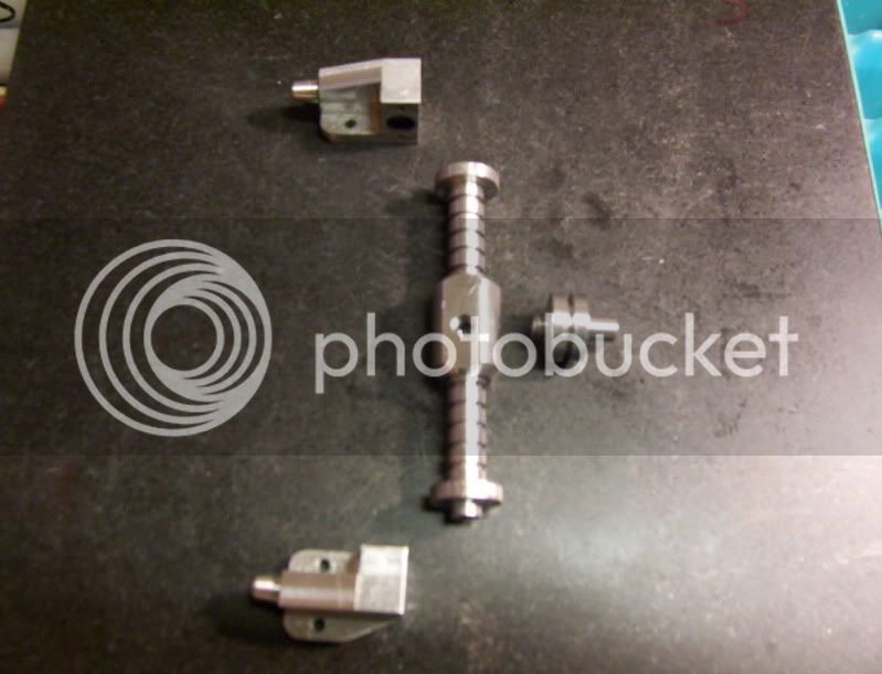
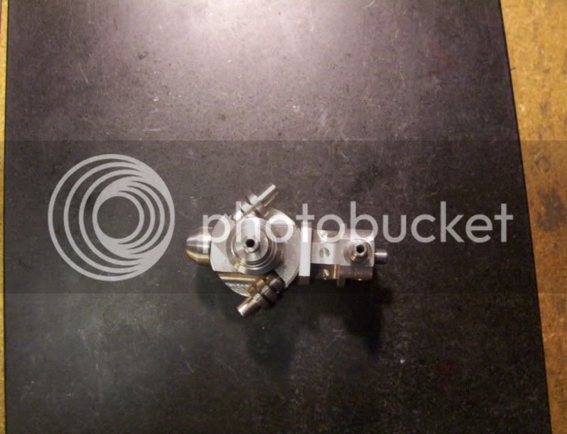
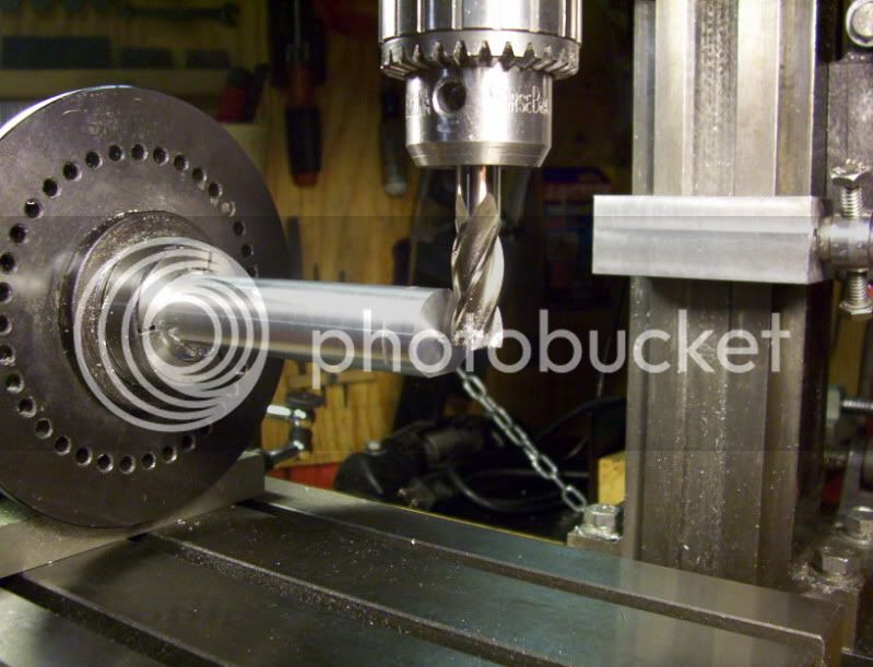
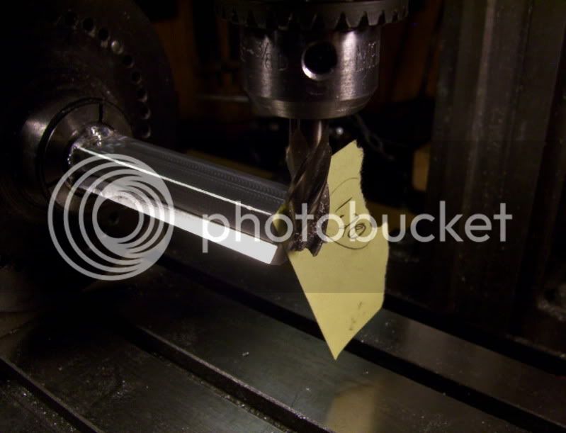
Now to set up and mill the front piece down to do the front profile.

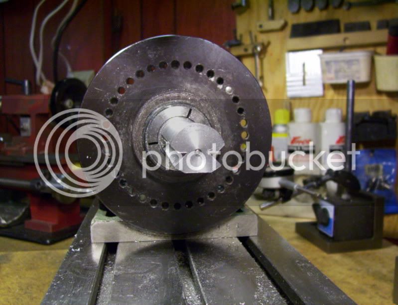
Move in 5/16" to a depth of 1/2" to profile the front end .
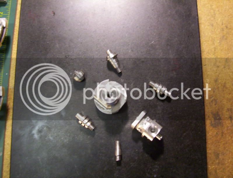
100_1623.jpg


100_1624.jpg


100_1625.jpg


100_1626.jpg


That's all for now.


Latest posts

Back
Top